Call Us
+86 136 6007 9809
Call Us
+86 136 6007 9809

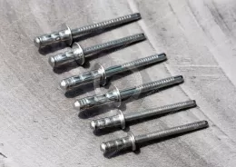
120° Countersunk Aluminum Multi-Grip Blind Rivets
JUXIN FASTENERS supplies aluminum-body multi-grip blind rivets with 120° countersunk heads and steel or stainless steel mandrels.
Designed for one-sided installation, these rivets accommodate varying panel thicknesses while allowing flush head seating in correctly prepared countersinks.
Suitable for compatible sheet-metal assemblies, equipment enclosures and OEM applications requiring controlled head clearance and grip-range flexibility.
Product Specification
120° Countersunk Aluminum Multi-Grip Blind Rivets
Product Overview
JUXIN FASTENERS supplies aluminum multi-grip blind rivets featuring a 120° countersunk head and a choice of steel or stainless steel pull mandrels.
These wide-grip-range blind rivets are designed for one-sided installation in assemblies where material thickness may vary and reduced fastener head projection is required.
The 120° countersunk head is intended to seat within a matching countersink, while the multi-grip construction accommodates a wider
range of combined material thicknesses than comparable conventional narrow-grip blind rivets.
This combination is relevant to OEM sheet-metal fabrication, industrial equipment enclosures and assemblies requiring both grip-range flexibility and controlled head clearance.
Material Combinations and Part Numbers
| Configuration | JUXIN Part Number | Rivet Body | Mandrel | Head Style |
|---|---|---|---|---|
| A | JX-AK-X-X BS | Aluminum | Steel | 120° Countersunk |
| B | JX-AK-X-X-SSBS | Aluminum | Stainless Steel | 120° Countersunk |
The original part number references are retained as supplied.
The exact aluminum alloy, steel grade, stainless steel grade and surface treatments must be confirmed against the approved technical documentation.
Product Features
Aluminum rivet body with steel or stainless steel mandrel options
120° countersunk head for compatible flush-mount applications
Multi-grip construction for varying material stack-ups
One-sided blind riveting installation
Reduced head projection when correctly installed
Suitable for compatible sheet-metal and enclosure assemblies
Potential reduction in rivet length variants after engineering validation
Customer-specific dimensional requirements subject to technical review
Technical Specifications
| Parameter | Specification |
|---|---|
| Product Type | Multi-Grip Blind Rivet |
| Head Style | 120° Countersunk Head |
| Rivet Body Material | Aluminum |
| Mandrel Material | Steel or Stainless Steel |
| Rivet Body Diameter (d) | Refer to original PDF/CAD |
| Rivet Body Length (L) | Refer to original PDF/CAD |
| Head Diameter (D) | Refer to original PDF/CAD |
| Countersunk Head Angle | 120° |
| Head Height | Refer to original PDF/CAD |
| Recommended Hole Diameter | According to selected rivet size |
| Minimum Grip Thickness | According to verified product data |
| Maximum Grip Thickness | According to verified product data |
| Shear Strength | According to verified product data |
| Tensile Strength | According to verified product data |
| Surface Finish | According to approved specification |
Technical Documentation: Refer to the existing product PDF/CAD specification, pages 95–96.
The original engineering drawings and dimensional tables govern the actual available sizes, tolerances and mechanical requirements.
120° Countersunk Head — Flush-Mount Engineering
The 120° countersunk head is the defining head geometry of this product.
When installed in a correctly prepared countersink, the rivet head can seat approximately flush with the accessible material surface.
This design may be useful where a protruding head could interfere with adjacent components or where reduced head projection is specified.
Critical engineering parameters include:
120° countersink angle
Countersink diameter and depth
Rivet head diameter and height
Mounting-hole diameter and tolerance
Panel material and thickness
Remaining material beneath the countersink
Head seating after installation
A 120° countersunk rivet requires compatible countersink geometry.
It should not be substituted for a countersunk rivet with a different head angle without checking the mating hole and joint requirements.
Incorrect countersink geometry may cause head protrusion, inadequate head support or localized panel deformation.
Multi-Grip Design and Wide Thickness Range
Multi-grip blind rivets are designed to accommodate a wider range of combined material thicknesses than comparable standard-grip designs.
The specified grip range defines the minimum and maximum material stack-up for which a selected rivet is intended.
For OEM assemblies using several panel thickness combinations, a suitable multi-grip rivet may cover more than one configuration.
However, the selected rivet must meet the installation and mechanical requirements at every intended material thickness.
Engineering Selection Matrix
| Selection Factor | Engineering Requirement |
|---|---|
| Minimum Material Stack-Up | Within verified minimum grip |
| Maximum Material Stack-Up | Within verified maximum grip |
| Countersink Angle | 120° |
| Countersink Diameter | Compatible with selected head |
| Mounting-Hole Diameter | According to rivet specification |
| Blind-Side Clearance | Sufficient for correct setting |
| Joint Performance | Verified for intended loading |
| Mandrel Material | Steel or stainless steel as specified |
The actual grip range must be obtained from the selected JUXIN product specification.
A wide grip range does not mean that one rivet is suitable for every material thickness.
Engineering Example — Variable Panel Thickness
Consider an OEM equipment enclosure with several panel configurations.
| Assembly | Illustrative Combined Thickness |
|---|---|
| Configuration A | 1.5 mm |
| Configuration B | 3.0 mm |
| Configuration C | 4.5 mm |
These values are illustrative engineering examples, not confirmed JUXIN product specifications.
A single multi-grip rivet could potentially be used across all three assemblies only if:
Its verified grip range covers the complete thickness interval.
The mounting-hole diameter is compatible.
The 120° countersink is correctly formed in each assembly.
The remaining panel material provides adequate support.
The installed joint meets the required mechanical performance.
This selection process can help manufacturing teams evaluate fastener standardization without assuming that different panel configurations are automatically interchangeable.
Steel vs. Stainless Steel Mandrels
Both product configurations use an aluminum rivet body. The difference is the pull mandrel material.
| Engineering Consideration | Steel Mandrel | Stainless Steel Mandrel |
|---|---|---|
| Rivet Body | Aluminum | Aluminum |
| Mandrel | Steel | Stainless Steel |
| Installation Tool | Must match selected configuration | Must match selected configuration |
| Mechanical Performance | Requires product-specific data | Requires product-specific data |
| Corrosion Suitability | Depends on grade, finish and environment | Depends on stainless grade and environment |
| Magnetic Behavior | Depends on steel specification | Depends on stainless grade and condition |
Aluminum Body + Steel Mandrel
This configuration uses a steel pull mandrel to deform the aluminum rivet body during installation.
The steel grade and mandrel finish should be specified for the intended application.
Aluminum Body + Stainless Steel Mandrel
This configuration uses a stainless steel pull mandrel with the aluminum rivet body.
The stainless steel grade and its compatibility with the mating materials and service environment should be evaluated.
Stainless steel mandrels are not automatically nonmagnetic, and they do not make the complete rivet a stainless steel fastener.
Neither mandrel configuration should be assigned a universal strength or corrosion-resistance advantage without verified product data.
Countersinking and Thin Sheet-Metal Design
Countersinking removes or displaces material around the mounting hole.
For thin panels, this can reduce the remaining material available to support the rivet head.
The engineer should evaluate:
Panel thickness before countersinking
Countersink depth
Remaining material beneath the head
Local bearing area
Panel stiffness
Expected joint loading
Installed head condition
A flush-mounted head is not necessarily the most suitable solution for every thin-sheet application.
Where a larger head-side bearing surface is required, a different rivet head configuration may be more appropriate.
Mounting-Hole Preparation and Tolerances
Correct hole preparation is essential for consistent blind riveting.
Important manufacturing controls include:
Mounting-hole diameter
Hole alignment
Burr removal
Countersink angle
Countersink depth
Surface condition
Material stack-up
Blind-side clearance
An oversized hole may reduce rivet support.
An undersized or misaligned hole may prevent proper insertion or damage the rivet during installation.
For production assemblies, hole and countersink dimensions should be controlled according to the approved engineering drawing.
Metric and Inch Diameter Reference
The following values are general nominal blind rivet diameter references.
| Metric Diameter | Approximate Inch Reference |
|---|---|
| 2.4 mm | 3/32 in |
| 3.2 mm | 1/8 in |
| 4.0 mm | 5/32 in |
| 4.8 mm | 3/16 in |
| 6.4 mm | 1/4 in |
These values are general dimensional references only and do not establish the available diameter range of this JUXIN product.
Actual metric and inch-designated rivets must be checked for dimensions, tolerances, grip ranges, mounting-hole requirements and functional compatibility before substitution.
Installation Method
These 120° countersunk multi-grip blind rivets require a compatible blind riveting tool and nosepiece.
A typical installation sequence is:
Prepare the mounting hole and 120° countersink according to the approved drawing.
Confirm the combined material thickness is within the selected rivet's grip range.
Align the joined components.
Insert the rivet into the prepared hole.
Seat the countersunk head correctly.
Engage the mandrel with the compatible riveting tool.
Pull the mandrel to deform the rivet body on the blind side.
Complete the setting operation at the designed mandrel break point.
Inspect head seating and blind-side formation.
The tool must be compatible with the selected rivet diameter, mandrel material and setting requirements.
Production Engineering and Assembly Efficiency
For manufacturing engineers and production managers, the multi-grip design may help simplify fastener selection across approved assemblies with different panel stack-ups.
Potential benefits include:
Fewer rivet length variants
Simplified fastener selection at assembly stations
Reduced risk of incorrect rivet length selection
More consistent assembly instructions
Easier inventory planning
Greater flexibility across approved product configurations
These benefits depend on verifying the actual grip range, countersink geometry and installed joint performance.
Tooling compatibility must also be checked when switching between steel and stainless steel mandrel configurations.
Mechanical Performance and Joint Reliability
Shear strength and tensile strength represent different loading conditions.
Actual performance depends on the selected rivet design, body diameter, material grades and mandrel configuration.
For 120° countersunk multi-grip rivets, the following factors are particularly important:
Minimum and maximum grip thickness
Countersunk head seating
Mounting-hole diameter
Remaining panel material
Blind-side formation
Rivet spacing and edge distance
Installation quality
Required shear and tensile performance
A wide grip range does not guarantee identical mechanical performance at every material thickness.
The complete installed joint should be evaluated against the applicable engineering requirements.
Corrosion and Material Compatibility
Aluminum, steel and stainless steel have different electrochemical characteristics.
The actual corrosion behavior of an installed rivet depends on:
Aluminum alloy grade
Steel or stainless steel mandrel grade
Surface coatings
Mating panel materials
Moisture and electrolyte exposure
Service environment
Dissimilar-metal contact can create galvanic corrosion concerns under suitable environmental conditions.
No specific corrosion rating or salt spray performance is claimed without supporting product data.
Typical Industrial Applications
120° countersunk aluminum multi-grip blind rivets may be considered for compatible applications such as:
Flush-mounted sheet-metal panels
Industrial equipment enclosures
Electrical and electronic equipment housings
Fabricated metal cabinets
Machinery covers and access panels
Equipment brackets
OEM assemblies with variable panel thickness
Industrial products requiring reduced fastener head projection
Application suitability depends on the actual rivet dimensions, grip range, material compatibility and joint performance requirements.
International Standards and Technical References
International blind rivet standards distinguish products according to construction, material combination, head geometry and dimensional requirements.
A 120° countersunk multi-grip rivet should not automatically be described as conforming to a standard intended for conventional dome head, different-angle countersunk or narrow-grip blind rivets.
Where ISO, DIN, EN or other international standards are required, the applicable standard, edition and scope must be verified against the actual product configuration.
The approved JUXIN engineering drawing and agreed customer specifications remain the controlling technical references until conformity is confirmed.
Inspection and Quality Requirements
Relevant inspection characteristics may include:
Rivet body diameter and length
120° countersunk head angle
Head diameter and height
Mandrel dimensions
Material identification
Minimum and maximum grip range
Mounting-hole compatibility
Countersink seating
Blind-side formation
Mandrel break condition
Shear and tensile performance where specified
Surface condition and packaging
Inspection methods and acceptance criteria should follow the approved engineering drawing and customer requirements.
OEM Customization and Bulk Supply
JUXIN FASTENERS supports drawing-based OEM sourcing for 120° countersunk aluminum multi-grip blind rivets.
Customer-specific requirements may include rivet diameter, body length, countersunk head geometry, grip range, mandrel material, surface finish, inspection criteria and packaging.
Technical feasibility and commercial terms are reviewed according to the required specifications and purchasing quantities.
Frequently Asked Questions
What is a 120° countersunk multi-grip blind rivet?
It is a blind rivet combining a wide grip range with a 120° countersunk head designed for compatible flush-mount applications.
What is the difference between this product and a standard countersunk blind rivet?
The multi-grip construction is intended to accommodate a wider range of combined material thicknesses than a comparable conventional narrow-grip design.
What is the difference between steel and stainless steel mandrel versions?
Both use aluminum rivet bodies. The mandrel materials differ, which can affect installation requirements, mechanical characteristics and corrosion considerations.
Do 120° countersunk rivets always sit flush?
No. Correct flush seating depends on the head dimensions, countersink geometry, panel material and installation conditions.
Can one multi-grip rivet replace several conventional rivet lengths?
Potentially, yes, provided all intended thicknesses fall within its verified grip range and the required joint performance is achieved.
Are stainless steel mandrel blind rivets nonmagnetic?
Not necessarily. Magnetic behavior depends on the stainless steel grade and its processing condition.
Are these rivets suitable for thin sheet metal?
They may be suitable where the countersink geometry, remaining panel thickness and joint requirements are compatible.
Can JUXIN supply custom 120° countersunk multi-grip blind rivets?
Customer-specific drawings and technical requirements can be submitted for engineering review and quotation.
Request an OEM 120° Countersunk Multi-Grip Blind Rivet Quotation
JUXIN FASTENERS supplies industrial blind rivets for OEM manufacturing and bulk purchasing projects.
For an accurate technical review and quotation, please provide:
Rivet body diameter and length
120° countersunk head diameter and height
Minimum and maximum material stack-up
Mounting-hole diameter and tolerance
Aluminum body alloy requirements
Steel or stainless steel mandrel grade
Surface finish requirements
2D engineering drawings or 3D CAD files
Required mechanical performance
Inspection and packaging requirements
Expected purchasing quantity and annual demand forecast
Target delivery schedule
Email: info@juxinfasteners.com
Website: https://www.juxinfasteners.com/
JUXIN FASTENERS — Industrial Multi-Grip Blind Rivets and Custom Fastening Solutions for Global OEM Applications.
Product Packaging
Packaging Standard
At Juxin Fasteners, we apply standardized export packaging to ensure product protection, traceability, and compliance with international logistics requirements.
1. Standard Export Packaging
Unless otherwise specified, all products will be packed according to our factory standard export packaging, which includes:
Moisture-resistant inner protection
Poly bag or small box packing as required
Reinforced export cartons
Clear labeling with part number, specification, batch number, and quantity
Palletizing for sea or air shipment when necessary
Our standard packaging is designed to ensure safe transportation, efficient warehousing, and long-distance international shipping.
2. Customized Packaging Options
We also provide customized packaging solutions according to customer requirements, including but not limited to:
Private labeling
Customized barcodes
Specific carton dimensions
Retail packaging
Special pallet configuration
Customer-specific marking and identification
So that you know, customized packaging may involve additional costs and extended lead time depending on the complexity of the requirements.
3. Compliance & Quality Assurance
All packaging processes are controlled under our ISO 9001 quality management system to ensure consistency, traceability, and product integrity throughout the supply chain.
Product Pictures


Contact Us
Tel.:
+86 020 8621 0320
+86 020 3121 6067
E-mail:
Technical Support:
Navigation
SEND INQUIREY