Call Us
+86 136 6007 9809
Call Us
+86 136 6007 9809

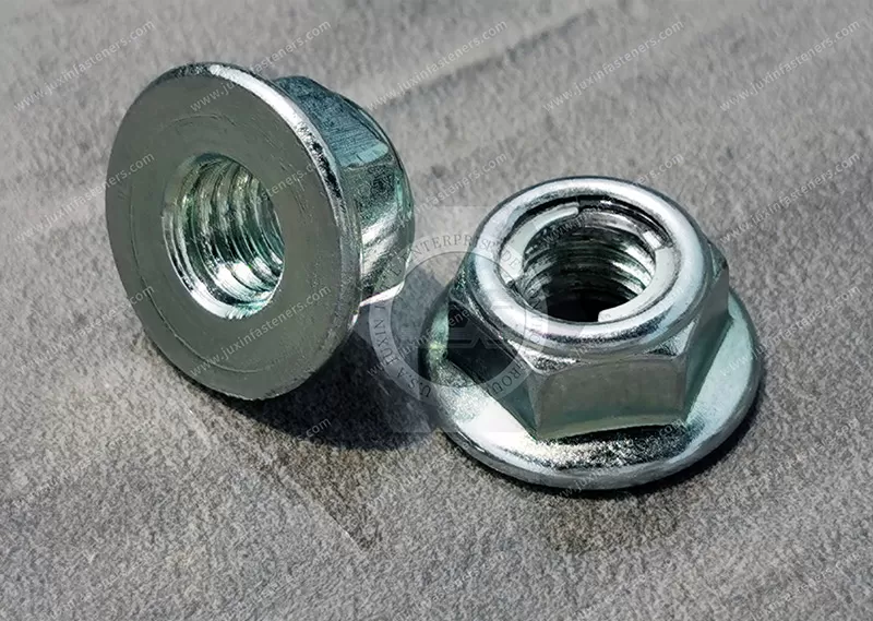
JUXIN FASTENERS supplies carbon steel hex flanged spring-stop locknuts for OEM machinery, automotive components, motorcycles and vibration-exposed equipment assemblies.
Also searched as Fuji-style flange lock nuts, these all-metal fasteners use an elastic metallic locking feature to generate prevailing torque without a nylon insert.
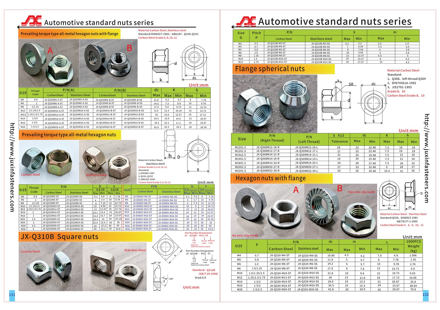
The original product information lists M5–M20 sizes, property classes 5, 6, 8 and 10, and zinc, zinc-nickel and zinc-flake coating options.
Depending on the approved design, the locking feature may use spring prongs or a specialized friction ring; the actual construction must be confirmed from the drawing.
Explore reusable locking performance, flange geometry, thread compatibility, ISO 2320 functional testing, material selection and custom OEM RFQs. DIN 6927 compliance requires separate verification.
Product Specification
Hex Flanged Spring-Stop Locknuts – Fuji-Style All-Metal Locking Solutions for OEM Assemblies
JUXIN FASTENERS supplies custom and standard-based carbon steel hex flanged spring-stop locknuts for automotive equipment, motorcycles,
industrial machinery, agricultural equipment, mechanical support systems and other industrial OEM applications.
These specialized locking nuts use an elastic metallic locking feature to create resistance against rotation on a compatible mating bolt.
In the American fastener market, related products are commonly called Spring-Stop Locknuts, Fuji-Style Flange Lock Nuts, Spring-Locking Flange Nuts and All-Metal Prevailing-Torque Locknuts.
Unlike conventional nylon-insert locknuts, spring-stop designs rely on metallic components to produce their locking action.
Certain designs use spring prongs or retaining teeth, while others use a separate metallic friction ring secured to the nut body.
These mechanisms are related but not necessarily interchangeable.
The actual spring-stop configuration, flange dimensions, material properties and functional performance must be established from the approved product drawing.
JUXIN FASTENERS supports drawing-based OEM inquiries for mechanical design engineers, manufacturing engineers, production managers, procurement engineers and global supply chain teams.
Product Overview and Technical Specifications
Product Name: Hex Flanged Spring-Stop Locknuts
American Industry Names:
Hex Flanged Spring-Stop Locknuts
Spring-Stop Flange Lock Nuts
Fuji-Style Flange Lock Nuts
Spring-Locking Hex Flange Nuts
All-Metal Spring Locknuts
Prevailing-Torque Flange Nuts
Material: Carbon Steel
Original Listed Property Classes:
Class 5
Class 6
Class 8
Class 10
Original Listed Metric Thread Sizes:
M5
M6
M8
M10
M12
M14
M16
M20
Original Listed Surface Treatment Options:
Clear Zinc Plating
Blue-Passivated Zinc Plating
Yellow Zinc Plating
Black Zinc Plating
Zinc-Nickel Alloy Plating
Zinc-Flake Coating
Dacromet-Type Coating, Subject to Specification
Product Configuration: Hexagon Nut with Integrated Flange and Metallic Spring Locking Feature
Locking Principle: Elastic Metallic Interference / Prevailing Torque
Original Standard Reference: DIN 6927
Functional Performance Reference: ISO 2320, where applicable
Mechanical Property Reference: ISO 898-2, subject to product applicability
Manufacturing Basis: Approved Engineering Drawings and Customer Specifications
The original range does not establish that every thread size, property class and surface finish combination is available.
The exact spring mechanism and DIN 6927 conformity must be verified for each product design.
What Is a Hex Flanged Spring-Stop Locknut?
A hex flanged spring-stop locknut is a threaded fastening component designed to resist unintended loosening through an elastic metallic locking mechanism.
A conventional hex nut normally rotates freely along a compatible bolt until it contacts the joint.
A spring-stop locknut incorporates a feature that creates additional rotational resistance during thread engagement.
Depending on the design, the locking feature may consist of:
Formed metallic spring prongs.
Spring-loaded retaining teeth.
A specialized metallic friction ring.
Another customer-specific elastic locking element.
The interference between the locking feature and mating bolt generates prevailing torque.
The integrated flange provides an enlarged bearing surface.
This combination can be useful for industrial assemblies requiring vibration resistance, compact fastening geometry and controlled installation performance.
How the Spring-Stop Locking Mechanism Works
Spring-stop locking relies on elastic interference rather than permanent deformation of the mating bolt thread as the intended locking principle.
During installation, the metallic locking feature contacts the mating bolt.
As the nut advances, the spring feature deflects and generates resistance to rotation.
This resistance contributes to the prevailing-torque locking action.
When the nut is removed, an appropriately designed elastic locking feature can recover some or much of its original shape.
This recovery supports repeated installation in designs qualified for reuse.
However, the actual number of permitted installation cycles depends on the product specification, spring geometry, material condition and functional testing.
Spring Prong Locking
Some spring-stop locknuts use formed prongs or retaining teeth.
The prongs engage the bolt thread and provide rotational resistance.
The number, geometry and orientation of the prongs depend on the manufacturer and design.
Metallic Friction Ring Locking
Other locknuts use a separate metallic friction ring.
The ring is secured to the nut body and contacts the mating bolt during installation.
Its elastic deformation generates prevailing torque.
The exact ring material, retention method and geometry must be confirmed from the drawing.
Spring-Stop Locknuts vs. Fuji-Style Locknuts
Fuji-style locknuts are associated with specialized all-metal locking designs.
The Japanese FUJILOK U-NUT system is known for its metallic friction-ring locking mechanism.
In the United States, some suppliers also use Fuji flange lock nut or spring-stop flange lock nut terminology for products with spring-tooth locking features.
These products belong to a related family of metal spring-locking fasteners, but their constructions may differ.
For custom OEM procurement, the buyer should specify the actual locking geometry rather than relying solely on a trade or catalog name.
The term Fuji-style is used here descriptively and does not establish that the product is manufactured or licensed by Fuji Seimitsu.
Spring-Stop Locknuts vs. Distorted-Thread Locknuts
This distinction is important for engineering selection.
Spring-Stop Locknuts
Use an elastic metallic locking feature such as spring prongs or a friction ring.
Potential advantages include repeatable locking behavior in designs validated for multiple installation cycles.
Distorted-Thread Locknuts
Use controlled deformation of the nut body or thread geometry to create prevailing torque.
The locking interference is produced by the deformed metallic section.
Engineering Difference
Both designs can resist unintended rotation.
However, they may differ in:
Locking feature geometry.
Prevailing-on torque.
Prevailing-off torque.
Reuse behavior.
Manufacturing process.
Installation characteristics.
Mechanical strength.
Temperature capability.
The correct product must be selected according to the joint design and functional requirements.
Spring-Stop Locknuts vs. Nylon-Insert Locknuts
Nylon-insert locknuts use a polymer insert to create thread interference.
Spring-stop locknuts use metallic locking features.
Potential Advantages of All-Metal Spring-Stop Designs
No nylon locking insert.
Potential suitability for selected elevated-temperature applications.
Elastic metallic locking action.
Repeated installation capability where validated.
Compatibility with selected industrial vibration environments.
Important Limitations
An all-metal construction does not automatically establish an unlimited temperature rating.
Repeated installation may eventually affect locking performance.
The nut must also have sufficient mechanical strength for the joint.
Neither design should be described as universally superior without comparative testing.
Integrated Hex Flange Design
The integrated flange provides a wider bearing surface than a comparable conventional hex nut.
Potential engineering benefits include:
Wider load distribution.
Reduced need for a separate plain washer in suitable assemblies.
Fewer loose assembly components.
Simplified parts handling.
Compatibility with selected automated assembly processes.
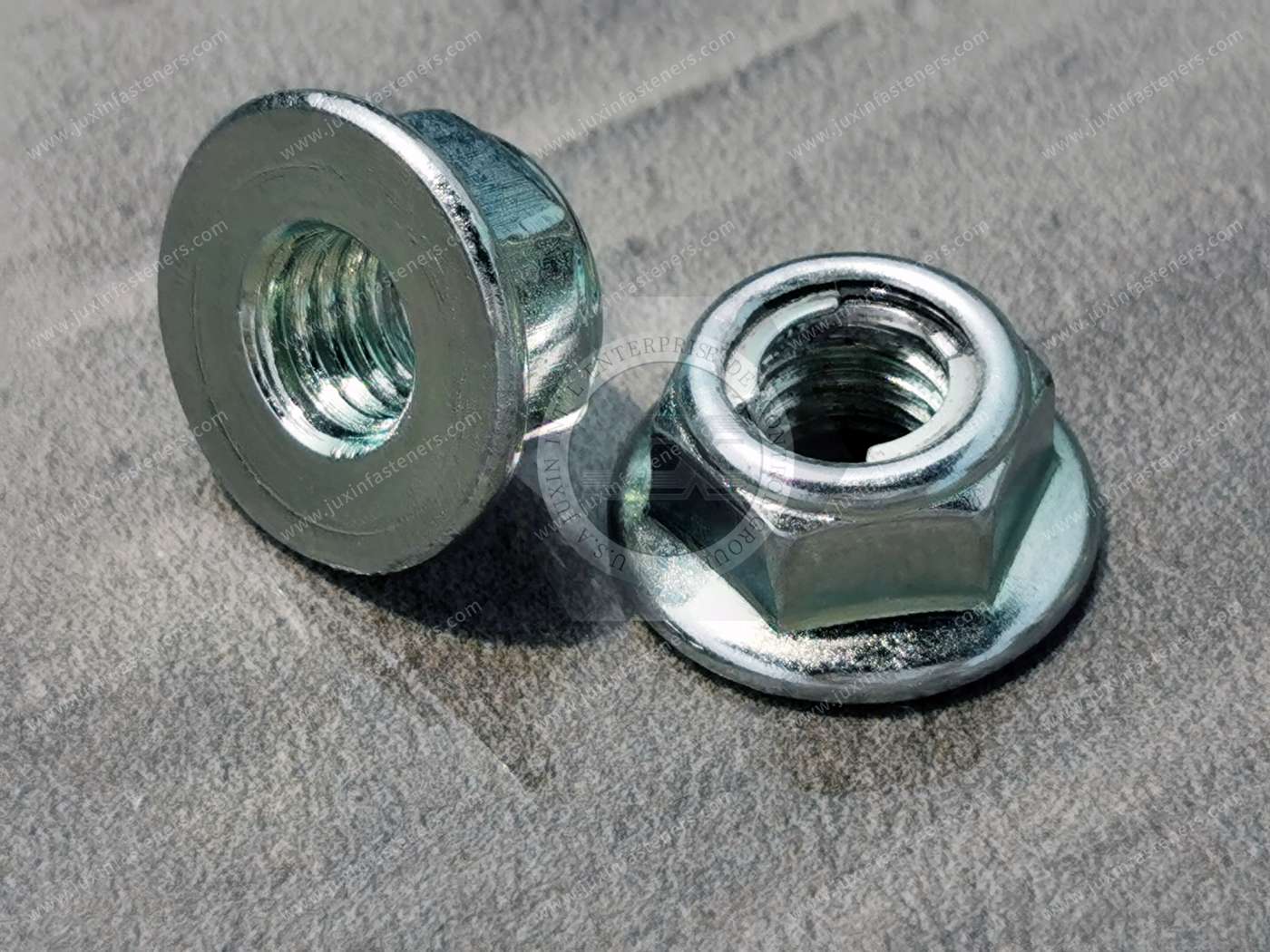
Some Fuji-style flange locknuts use a smooth, non-serrated bearing surface.
A smooth flange can be relevant where the designer wants to avoid the surface effects of serrated locking hardware.
However, the exact flange configuration must be confirmed.
Flange Engineering Considerations
Flange diameter.
Bearing surface geometry.
Hole diameter.
Workpiece material.
Surface hardness.
Edge distance.
Assembly clearance.
Required clamp force.
The flange does not automatically compensate for oversized or damaged holes.
Carbon Steel Material Selection
The original product information identifies carbon steel.
Carbon steel may be appropriate for many industrial fastener applications where the mechanical requirements and environmental conditions are compatible.
Material selection should consider:
Required nut property class.
Mating bolt strength.
Spring feature material.
Heat treatment.
Fatigue performance.
Corrosion exposure.
Manufacturing feasibility.
Production cost.
If the design uses a separate spring ring, the nut body and spring ring may require different material specifications.
The material of each component must be verified.
Property Classes 5, 6, 8 and 10
The original product range lists four property classes.
However, these designations must be interpreted against the applicable product and mechanical standards.
Class 5 and Class 6
These may be relevant to selected lower-strength fastening applications, subject to the product specification.
Class 8
Class 8 may be selected for industrial assemblies requiring the corresponding nut mechanical properties.
Class 10
Class 10 may be relevant to certain higher-strength bolted joints.
Critical Engineering Requirement
The nut body, locking feature and mating bolt must be evaluated as a complete system.
A spring-stop nut should not be described as Class 10 solely because its hexagon body resembles a conventional Class 10 nut.
Mechanical properties and locking performance require appropriate verification.
DIN 6927 Standard Reference and Compatibility
The original product information lists DIN 6927.
DIN 6927 is associated with prevailing-torque all-metal hexagon flange nuts.
Related standard references include DIN EN 1664 and ISO 7044.
However, these standard designations do not automatically define the specific spring-prong or metallic friction-ring geometry of every Fuji-style locknut.
The engineering drawing should establish whether the supplied component is:
Fully compliant with the specified standard.
Dimensionally based on a standard.
A customer-specific spring-stop design.
A proprietary-style locking configuration.
For an OEM replacement project, verify:
Thread diameter and pitch.
Nut height.
Width across flats.
Flange diameter.
Locking feature height.
Locking geometry.
Mechanical property class.
Prevailing-torque performance.
Surface treatment.
Standard compatibility should be confirmed before substitution.
ISO 2320 and Prevailing-Torque Performance
ISO 2320 provides functional requirements and test methods for prevailing-torque steel nuts.
Where applicable to the specified product, it can provide a basis for evaluating locking performance.
Important characteristics include:
Prevailing-On Torque
The torque required to advance the nut on a compatible mating thread before significant clamp force develops.
Prevailing-Off Torque
The torque required to rotate the nut during removal after the joint clamp force has been relieved.
Repeated Installation Performance
A reusable spring-stop design should maintain the required locking performance through the customer-specified installation cycles.
Proof Load
The nut must also meet the applicable mechanical loading requirements.
Prevailing torque and proof-load capability are separate engineering characteristics.
Can Spring-Stop Locknuts Be Reused?
Certain spring-stop locknuts are designed for repeated installation and removal.
Their elastic locking features can provide better retention of locking function over multiple cycles than some permanently deformed locking designs.
However, reuse performance depends on:
Spring feature geometry.
Material properties.
Surface treatment.
Mating bolt condition.
Thread wear.
Installation torque.
Operating temperature.
Number of installation cycles.
The permissible reuse limit should be defined by the applicable product specification or customer testing.
A nut should not be reused in a safety-critical joint without the required engineering approval.
Available Metric Thread Sizes
The original product information lists:
M5
M6
M8
M10
M12
M14
M16
M20
Common ISO metric coarse thread designations for reference include:
M5 × 0.8
M6 × 1.0
M8 × 1.25
M10 × 1.5
M12 × 1.75
M14 × 2.0
M16 × 2.0
M20 × 2.5
These are reference thread designations.
The actual pitch, thread tolerance, nut dimensions and locking mechanism must be confirmed for each ordered size.
Metric and Inch Thread Compatibility
American buyers may search for similar spring-stop locknuts in UNC or UNF thread sizes.
However, the original product range is metric.
Metric and Unified inch-series threads are not interchangeable.
For example:
M6 is not interchangeable with 1/4"-20 UNC.
M8 is not interchangeable with 5/16"-18 UNC.
M10 is not interchangeable with 3/8"-16 UNC.
Inch-series requirements must be reviewed as separate specifications.
Surface Treatment and Corrosion Protection
The original product range includes several coating options.
Surface treatment selection should consider:
Corrosion exposure.
Coating thickness.
Thread fit.
Friction behavior.
Locking feature movement.
Prevailing torque.
Environmental compliance.
Customer appearance requirements.
Clear Zinc Plating
Clear zinc plating can provide corrosion protection in suitable industrial environments.
Performance depends on the complete coating system.
Blue-Passivated Zinc Plating
Blue-passivated zinc may be specified for selected industrial applications.
Yellow Zinc Plating
Yellow zinc finishes may be supplied according to customer requirements, subject to approved passivation chemistry.
Black Zinc Plating
Black zinc finishes provide a dark appearance with corrosion protection determined by the complete coating specification.
Zinc-Nickel Alloy Plating
Zinc-nickel coatings may be considered for more demanding corrosion requirements.
Actual performance depends on coating thickness, passivation and topcoat.
Zinc-Flake Coating
Zinc-flake systems may be appropriate for selected industrial fasteners.
Coating thickness and friction characteristics must be coordinated with the locking mechanism.
Dacromet-Type Coating
Dacromet is associated with particular zinc-flake coating technologies.
The actual approved coating chemistry and environmental compliance must be confirmed.
Coating Standards
Relevant standards may include:
ISO 4042 for electroplated fastener coatings.
ISO 10683 for non-electrolytically applied zinc-flake coatings.
The actual coating specification should define the required corrosion performance and acceptance criteria.
Coating Effects on the Spring Locking Feature
A spring-stop locknut includes an elastic locking element.
Coating thickness or coating buildup can affect the movement and contact characteristics of this feature.
Potential engineering concerns include:
Increased installation resistance.
Reduced spring movement.
Coating damage.
Friction variation.
Inconsistent prevailing torque.
Mating thread wear.
For OEM production, the coated fastener should be evaluated in its finished condition.
Temperature and Vibration Considerations
All-metal spring-stop locknuts may be considered for applications where polymer locking inserts are unsuitable.
However, actual temperature capability depends on:
Nut body material.
Spring feature material.
Heat treatment.
Coating.
Mating bolt.
Required locking performance.
Similarly, vibration resistance must be established according to the actual joint design.
No universal temperature rating or vibration qualification is established by the supplied product information.
Industrial Applications and Engineering Solutions
1. Automotive Mechanical Assemblies
Automotive manufacturers may use spring-stop locking nuts for selected vibration-exposed mechanical connections.
Potential applications include:
Equipment brackets.
Mechanical mounting assemblies.
Auxiliary support hardware.
Selected serviceable components.
Engineering Challenge
Vibration and repeated mechanical loading can contribute to unintended fastener rotation.
Potential Solution
A spring-stop flange locknut may provide a reusable metallic prevailing-torque feature when the joint design and customer specifications permit.
2. Motorcycle Equipment and Accessories
Motorcycles contain mechanical assemblies exposed to vibration and repeated service operations.
Potential applications include:
Accessory mounting hardware.
Equipment brackets.
Selected mechanical supports.
Serviceable assemblies.
Engineering Challenge
The fastener may require locking resistance together with convenient installation and removal.
Potential Solution
A qualified spring-stop design may be considered where repeated service and vibration resistance are important.
3. Industrial Machinery
Industrial machinery often includes mechanical components subject to vibration.
Potential applications include:
Equipment frames.
Machine covers.
Support brackets.
Auxiliary mounting hardware.
Engineering Challenge
Repeated machine operation may affect joint retention.
Potential Solution
A spring-stop flange locknut may provide a suitable locking feature as part of a properly designed bolted joint.
4. Agricultural Machinery
Agricultural equipment operates under vibration, dirt and changing environmental conditions.
Potential applications include:
Implement accessories.
Mechanical brackets.
Equipment supports.
Serviceable assemblies.
Engineering Challenge
The joint may need both retention and practical maintenance access.
Potential Solution
A reusable spring-stop locknut may be evaluated according to the required locking performance and corrosion specification.
5. Heavy Equipment and Construction Machinery
Heavy equipment contains mechanical assemblies exposed to shock and dynamic loading.
Engineering Challenge
The connection may require resistance to unintended rotation under demanding operating conditions.
Potential Solution
A spring-stop flange locknut can be evaluated where its mechanical property class and locking performance satisfy the approved design.
Safety-critical connections require dedicated validation.
6. Rail and Transportation Equipment
Rail and transportation systems contain mechanical assemblies exposed to vibration.
Engineering Challenge
Long service intervals and dynamic loading can increase the importance of fastening reliability.
Potential Solution
A specified all-metal spring-stop locking nut may be considered when permitted by the applicable equipment requirements.
Rail-specific qualifications must be confirmed separately.
7. HVAC and Thermal Management Equipment
HVAC equipment contains vibration-producing components such as fans, pumps and compressors.
Potential applications include:
Fan support brackets.
Equipment mounting hardware.
Mechanical frames.
Auxiliary support components.
Engineering Challenge
Vibration and temperature changes may affect joint retention.
Potential Solution
A suitable all-metal spring-stop flange nut may be evaluated for the mechanical fastening requirement.
8. Electric Motors and Industrial Drives
Electric motor assemblies may experience vibration and thermal cycling.
Engineering Challenge
The joint may require reliable retention while remaining serviceable.
Potential Solution
A spring-stop locknut can be considered where its locking characteristics and mechanical strength meet the equipment requirements.
9. Electrical Equipment and Power Distribution
Electrical equipment manufacturers may require secure mechanical mounting connections.
Potential applications include:
Equipment brackets.
Enclosure supports.
Auxiliary mounting assemblies.
Mechanical support frames.
Engineering Challenge
The connection may experience vibration or thermal cycling.
Potential Solution
An all-metal flange locknut may be evaluated for suitable mechanical joints.
Electrical insulation and grounding requirements must be addressed separately.
10. AI Data Center Cooling and Mechanical Infrastructure
AI data centers contain mechanical support systems associated with cooling, power and computing equipment.
Potential applications include:
Cooling equipment brackets.
Pump support hardware.
Mechanical equipment frames.
Auxiliary rack hardware.
Engineering Challenge
Some mechanical systems operate continuously and may produce vibration.
Potential Solution
A spring-stop locking nut may be evaluated where the joint design requires metallic prevailing-torque resistance and maintenance access.
Suitability must be established for the actual equipment specification.
11. Industrial Automation and Production Lines
Automated manufacturing equipment contains numerous mechanical brackets and support connections.
Engineering Challenge
The equipment may require repeatable fastening performance and efficient maintenance.
Potential Solution
A suitable spring-stop flange locknut may provide an alternative to other locking systems, subject to validation.
12. General OEM Equipment Manufacturing
Potential applications include:
Mechanical brackets.
Equipment covers.
Serviceable assemblies.
Fabricated metal structures.
Custom machinery accessories.
Engineering Challenge
Standard locking nuts may not provide the desired combination of flange geometry, locking behavior and reusability.
Potential Solution
A customer-specific spring-stop locking nut can be evaluated according to the engineering drawing.
Installation and Assembly Engineering
Spring-stop locknuts require careful consideration of installation torque and locking resistance.
Step 1: Confirm the Mating Bolt
Verify thread size, pitch, property class and surface condition.
Step 2: Inspect the Locking Feature
Check that the spring prongs or metallic friction ring are intact.
Step 3: Align the Threads
Start the nut correctly to avoid cross-threading.
Step 4: Engage the Locking Feature
Advance the nut according to the approved assembly procedure.
Step 5: Apply the Required Tightening Method
Use the specified installation tool and tightening requirements.
Step 6: Verify the Joint
Confirm seating, clamp force where required, and the finished assembly condition.
Important Torque Consideration
The measured installation torque includes the influence of the locking feature and friction.
Prevailing torque must not be confused with clamp force.
Generic torque tables may be insufficient for critical spring-stop locking assemblies.
Automated Assembly and Production Management
For production managers, a spring-stop locknut affects both component cost and assembly behavior.
Important factors include:
Nut feeding and orientation.
Locking feature consistency.
Thread starting.
Installation torque.
Assembly tool capacity.
Cycle time.
Coating friction.
Inspection requirements.
Rework.
Maintenance procedures.
Repeat-order consistency.
A reusable locking design may offer operational advantages in selected serviceable assemblies.
However, actual cost savings must be established from production and maintenance data.
Common Engineering Problems and Corrective Measures
Problem 1: Excessive Installation Torque
Possible causes include incorrect locking geometry, coating buildup or incompatible mating threads.
Review the finished nut and bolt specifications.
Problem 2: Insufficient Prevailing Torque
Possible causes include spring feature deformation, wear or manufacturing variation.
Review the specified locking performance and inspection criteria.
Problem 3: Spring Feature Damage
Possible causes include incorrect assembly, unsuitable tools or excessive loading.
Inspect the locking feature and review the installation process.
Problem 4: Thread Damage
Possible causes include cross-threading or incompatible thread specifications.
Verify the mating components.
Problem 5: Inconsistent Clamp Force
Possible causes include friction variation or incorrect tightening procedures.
Review the actual torque/clamp-force relationship.
Problem 6: Corrosion
Possible causes include unsuitable material or coating selection.
Review the operating environment and approved coating specification.
Problem 7: Reduced Reuse Performance
Possible causes include wear, spring fatigue or damage during installation and removal.
Review the allowed installation cycles and functional test requirements.
Problem 8: Joint Loosening Under Vibration
Possible causes include inadequate preload, joint settlement or insufficient locking performance.
Evaluate the complete bolted joint.
Quality Inspection for Spring-Stop Flange Locknuts
Quality requirements should follow the approved engineering drawing and customer specifications.
Dimensional Inspection
Potential characteristics include:
Thread diameter.
Thread pitch.
Nut height.
Width across flats.
Flange diameter.
Flange thickness.
Spring feature geometry.
Locking feature position.
Critical dimensional tolerances.
Material Verification
Verify the specified carbon steel and, where applicable, the spring element material.
Mechanical Property Verification
Confirm the required property class and applicable mechanical requirements.
Prevailing-Torque Testing
Potential tests include:
Prevailing-on torque.
Prevailing-off torque.
Repeated installation/removal performance.
Torque/clamp-force behavior.
Spring Feature Inspection
Inspect for:
Cracks.
Deformation.
Incorrect positioning.
Retention defects.
Surface damage.
Other conditions affecting locking performance.
Coating Inspection
Potential requirements include:
Coating type.
Coating thickness.
Surface appearance.
Corrosion resistance.
Friction characteristics.
Environmental compliance.
Functional Assembly Validation
Depending on the application, customer testing may include:
Mating bolt compatibility.
Installation torque.
Reuse performance.
Vibration resistance.
Temperature exposure.
Corrosion exposure.
Joint retention.
These are possible customer-defined validation requirements, not claims that every test is performed on every production lot.
OEM and Automotive Quality Documentation
Depending on customer requirements, documentation may include:
Approved engineering drawings.
Material specifications.
Dimensional inspection reports.
Mechanical property reports.
Prevailing-torque test reports.
Coating specifications.
Corrosion test reports.
First article inspection.
Traceability.
Process control records.
PPAP documentation where applicable.
Engineering change control.
Specific certifications and customer approvals must be supported by the appropriate records.
Custom Spring-Stop Flange Locknuts to Engineering Drawings
JUXIN FASTENERS supports technical inquiries for customer-specific hex flanged spring-stop locknuts and related all-metal locking fasteners.
Custom requirements may include:
Metric thread size.
Thread pitch.
Nut property class.
Flange dimensions.
Hexagon dimensions.
Spring prong geometry.
Metallic friction-ring design.
Prevailing-torque requirements.
Repeated installation performance.
Surface coating.
Corrosion resistance.
Friction requirements.
Temperature requirements.
Quality documentation.
Packaging.
Production volume.
Manufacturing feasibility and quotation depend on the approved technical requirements.
Frequently Asked Engineering Questions
What is a hex flanged spring-stop locknut?
It is a flange nut with a metallic spring locking feature that creates prevailing torque on a compatible mating bolt.
What is the American name for this product?
Common terms include Spring-Stop Locknuts, Hex Flanged Spring-Stop Locknuts and Fuji-Style Flange Lock Nuts.
Are Fuji-style locknuts and distorted-thread locknuts the same?
No. Fuji-style spring-locking designs generally use an elastic locking element, while distorted-thread nuts use controlled metallic deformation.
Are all Fuji-style locknuts identical?
No. Different designs may use spring prongs, retaining teeth or specialized friction rings.
Can spring-stop locknuts be reused?
Certain designs are intended for repeated installation. Actual reuse limits depend on the approved specification and functional testing.
Are these locknuts suitable for high temperatures?
All-metal designs may be suitable for selected elevated-temperature applications, but actual temperature capability requires validation.
What material is used?
The original product information identifies carbon steel.
What property classes are listed?
Classes 5, 6, 8 and 10 are listed in the original information, subject to verification for each design and size.
What metric sizes are listed?
M5, M6, M8, M10, M12, M14, M16 and M20.
Are these nuts DIN 6927 compliant?
DIN 6927 is listed in the original information, but compliance of the specific spring-stop design must be verified.
Do these nuts require separate washers?
An integrated flange may eliminate a separate plain washer in suitable assemblies.
Can these nuts be used in automotive applications?
They may be suitable for selected automotive mechanical assemblies when approved according to the customer requirements.
Are spring-stop nuts better than nylon-insert nuts?
The answer depends on the required temperature, locking performance, reuse characteristics and joint design.
Can metric spring-stop nuts be used with UNC bolts?
No. Metric and UNC threads are not directly interchangeable.
Can JUXIN FASTENERS evaluate custom spring-stop nut drawings?
Yes. Customer-specific inquiries can be reviewed according to the supplied drawings and production requirements.
What information is required for an OEM quotation?
A dimensioned drawing, material specification, locking feature design, thread size, property class, coating requirements, prevailing-torque criteria and estimated annual quantity provide a useful basis for review.
Request a Custom Hex Flanged Spring-Stop Locknut RFQ
JUXIN FASTENERS supports OEM sourcing and engineering inquiries for hex flanged spring-stop locknuts, Fuji-style flange locking nuts and specialized all-metal prevailing-torque fasteners.
For a new OEM program or an existing production component, please provide:
2D engineering drawing or 3D CAD file.
Required product standard, if applicable.
Metric thread size and pitch.
Required property class.
Mating bolt specification.
Nut height and width across flats.
Flange diameter and thickness.
Spring locking feature geometry.
Prevailing-on torque requirements.
Prevailing-off torque requirements.
Reuse cycle requirements.
Surface coating specification.
Corrosion resistance requirements.
Friction requirements.
Operating temperature and environment.
Quality and inspection requirements.
Initial order quantity.
Estimated annual production demand.
Target delivery schedule.
Our team can review the technical specifications and discuss engineering clarification, manufacturing feasibility and quotation.
JUXIN FASTENERS
Website: https://www.juxinfasteners.com/
Email: info@juxinfasteners.com
Submit Your Engineering Drawings for a Custom Hex Flanged Spring-Stop Locknut RFQ.
Product Packaging
Packaging Standard
At Juxin Fasteners, we apply standardized export packaging to ensure product protection, traceability, and compliance with international logistics requirements.
1. Standard Export Packaging
Unless otherwise specified, all products will be packed according to our factory standard export packaging, which includes:
Moisture-resistant inner protection
Poly bag or small box packing as required
Reinforced export cartons
Clear labeling with part number, specification, batch number, and quantity
Palletizing for sea or air shipment when necessary
Our standard packaging is designed to ensure safe transportation, efficient warehousing, and long-distance international shipping.
2. Customized Packaging Options
We also provide customized packaging solutions according to customer requirements, including but not limited to:
Private labeling
Customized barcodes
Specific carton dimensions
Retail packaging
Special pallet configuration
Customer-specific marking and identification
So that you know, customized packaging may involve additional costs and extended lead time depending on the complexity of the requirements.
3. Compliance & Quality Assurance
All packaging processes are controlled under our ISO 9001 quality management system to ensure consistency, traceability, and product integrity throughout the supply chain.
Product Pictures
Contact Us
Tel.:
+86 020 8621 0320
+86 020 3121 6067
E-mail:
Technical Support:
Navigation
SEND INQUIREY