Call Us
+86 136 6007 9809
Call Us
+86 136 6007 9809

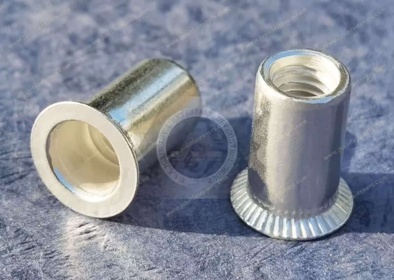
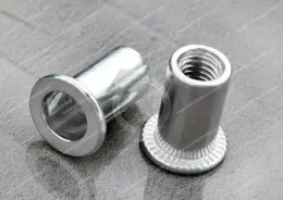
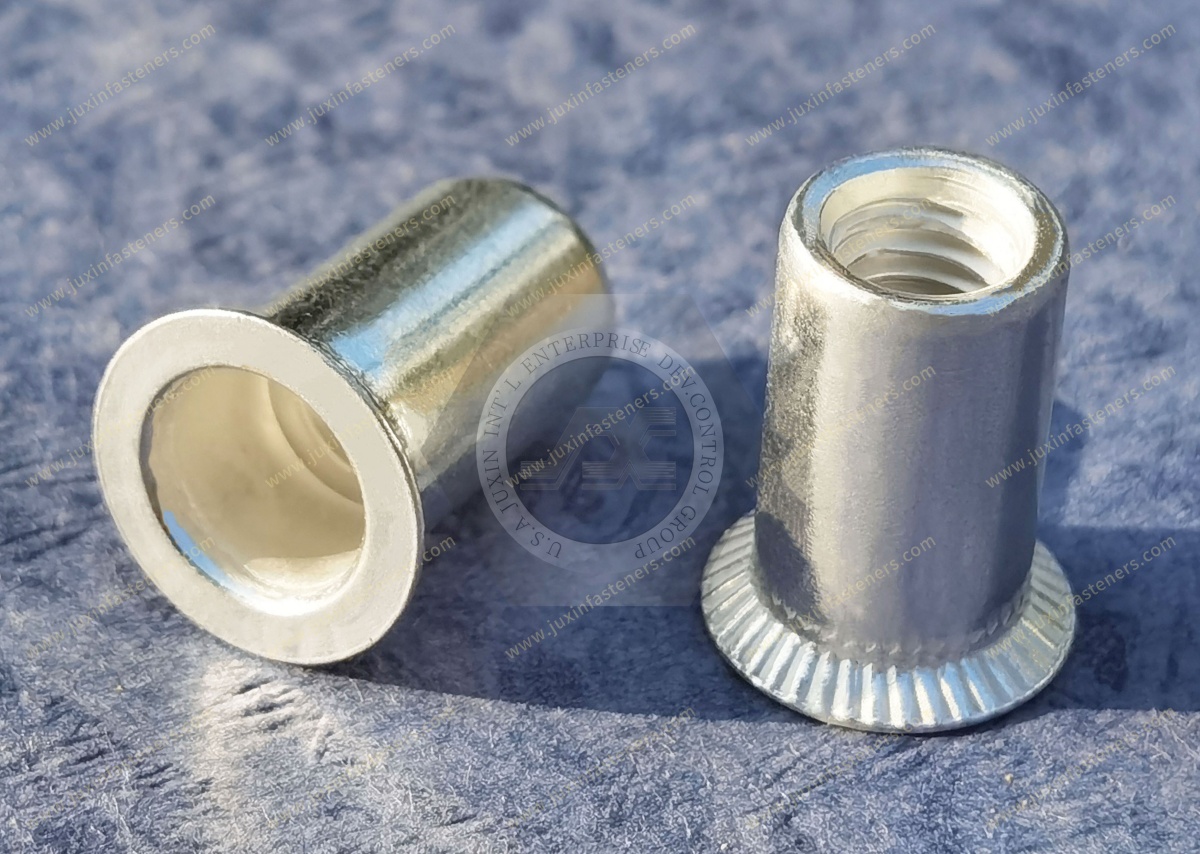
JUXIN FASTENERS supplies aluminum countersunk head open-end plain round body blind rivet nuts for OEM sheet-metal assemblies requiring reusable internal threads, one-sided installation, and reduced flange projection through a matching countersunk mounting hole.
The countersunk head is designed to seat in a properly prepared recess, potentially providing a flush or near-flush installed surface when the head geometry and countersink dimensions are correctly matched. The smooth cylindrical body is intended for a compatible round mounting hole, while the open-end barrel allows screw extension where backside clearance is available.
Product Features
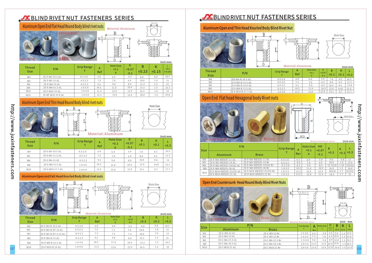
Thread sizes: M4, M5, M6, M8, M10
Material: Aluminum
Product-family grip range: 1.5–5.0 mm (approx. 0.059–0.197 in)
Head: Countersunk head
Body: Plain round / Smooth cylindrical body
End: Open end
Installation: One-sided blind installation
Mounting hole: Round hole with compatible countersink
Countersink angle and depth: According to approved drawing
Aluminum alloy and temper: Subject to confirmation
OEM dimensions: Drawing-based technical review
Potential applications include automotive equipment panels, electronic enclosures, industrial machinery covers, lightweight fabricated housings, HVAC equipment, transportation components, and other sheet-metal assemblies requiring controlled mounting-surface projection.
For OEM technical review and quotations, contact info@juxinfasteners.com.
Product Specification
Aluminum Countersunk Head Open-End Plain Round Body Blind Rivet Nuts – Flush-Mount OEM Fastening Solutions
JUXIN FASTENERS supplies aluminum countersunk head open-end plain round body blind rivet nuts for OEM manufacturers requiring reusable threaded fastening points in thin-walled panels and hollow fabricated structures.
This product combines a countersunk flange, smooth cylindrical body, open-end internal thread, and aluminum construction.
The countersunk head is designed to fit a corresponding recess in the accessible side of the parent panel. When the insert and mounting-hole geometry are correctly matched, this arrangement can reduce flange projection and help accommodate closely fitted covers, brackets, and mating components.
Unlike a conventional flat-head rivet nut, the countersunk design requires additional consideration of recess geometry and remaining parent-material thickness.
The product is intended for one-sided blind installation, making it relevant to assemblies where conventional nuts cannot easily be positioned behind the panel.
Product Specifications
Product type: Aluminum Countersunk Head Open-End Plain Round Body Blind Rivet Nut
Material: Aluminum
Metric thread sizes: M4, M5, M6, M8, M10
Head configuration: Countersunk head
Body configuration: Plain round body / Smooth cylindrical shank
End configuration: Open end
Product-family grip range: 1.5–5.0 mm
Approximate inch reference: 0.059–0.197 in
Installation method: One-sided blind installation
Mounting-hole geometry: Round hole with a compatible countersink
Countersink angle: According to approved drawing
Countersink depth: According to approved drawing
Aluminum alloy and temper: Subject to confirmation
Thread pitch and tolerance class: According to approved drawing
Flange outside diameter: According to approved drawing
Body diameter and length: According to approved drawing
Installed backside projection: Subject to installation validation
Mechanical retention performance: Subject to product-specific testing
The specified 1.5–5.0 mm grip range represents the product family. The approved grip range for each individual thread size must be verified against the selected drawing.
Engineering Design and Selection
Why Choose a Countersunk Head Blind Rivet Nut?
A countersunk head rivet nut is intended for applications where the installed flange must occupy a recess rather than sit entirely above the mounting surface.
This may be useful when:
A cover must fit closely against a panel
A bracket requires a controlled mating surface
Surface projection must be minimized
Equipment packaging space is limited
A visible fastening point must meet defined appearance requirements
One-sided threaded fastening is required
However, the countersunk head alone does not guarantee a flush installation.
The final installed position depends on the head geometry, countersink dimensions, panel condition, and installation process.
Countersunk Head vs. Thin Head vs. Flat Head
These three head configurations solve different engineering problems.
Flat Head Rivet Nuts
A conventional flat-head design provides a flange that sits against the accessible surface of the parent panel.
The flange normally projects above the surrounding surface.
Thin Head Rivet Nuts
A thin-head or reduced-head design minimizes flange projection without necessarily requiring a countersunk mounting hole.
The installed head may still remain above the parent-panel surface.
Countersunk Head Rivet Nuts
A countersunk design uses a matching recess to accommodate the flange.
It may provide a flush or near-flush installed surface when the geometry is properly matched.
The correct selection depends on:
Available panel thickness
Required surface clearance
Flange-bearing requirements
Mounting-hole manufacturing capability
Axial retention requirements
Installation cost
These head styles should not be treated as interchangeable without dimensional and mechanical verification.
Countersink Angle and Head Compatibility
The countersink angle is a critical design dimension.
The angle of the mounting recess must be compatible with the selected rivet nut head.
An incorrect angle can produce uneven seating, local contact stresses, or unwanted flange projection.
Engineers should verify:
Countersunk head angle
Mounting recess angle
Countersink major diameter
Countersink depth
Head thickness
Head outside diameter
Surface flatness
No universal countersink angle is assumed for this product family.
The approved dimensional drawing must define the required geometry.
Countersink Depth and Installed Head Projection
The countersink depth influences the final position of the installed flange.
An insufficiently deep recess may leave the head projecting above the panel.
An excessively deep recess may reduce local panel support or place the head below the intended surface.
Both conditions can affect assembly fit and mechanical behavior.
For production approval, the OEM should define the acceptable installed head projection relative to the surrounding panel.
This requirement should be verified after the rivet nut has been installed, not solely from the uninstalled component dimensions.
Remaining Panel Thickness After Countersinking
One of the most important engineering considerations is the amount of parent material remaining around the countersunk mounting hole.
The countersink removes material from the accessible side of the panel.
This can reduce the local section available to support the flange and surrounding joint.
For thin sheet metal, an aggressive countersink may increase the risk of local deformation or pull-through.
Engineers should evaluate:
Original panel thickness
Countersink depth
Remaining material thickness
Parent-material strength
Hole geometry
Flange-bearing area
Applied axial loading
A countersunk rivet nut should not be selected solely because the nominal panel thickness falls within the published grip range.
The complete installation geometry must also be suitable.
Grip Range and Countersunk Panel Geometry
This product family has a specified grip range of 1.5–5.0 mm.
The grip range must be interpreted according to the selected product drawing and installation instructions.
For countersunk installations, the relationship between panel thickness, countersink depth, and the effective gripping geometry requires particular attention.
It should not be assumed that a panel of nominal thickness 1.5 mm is suitable for every countersink depth or every thread size.
Where the panel thickness approaches a grip limit, the installation should be evaluated using representative production material.
Flange Pull-Through and Local Panel Failure
Countersunk rivet nuts transfer loads through the installed insert and surrounding parent material.
Under axial loading, the countersunk flange and remaining panel section must provide adequate support.
Potential failure mechanisms include:
Local panel deformation
Flange pull-through
Insert displacement
Parent-material tearing
Backside retaining-bulge deformation
The governing failure mode depends on the loading direction, material properties, and joint geometry.
Where axial retention is critical, testing should use the actual panel material, countersink dimensions, and installation parameters.
Plain Round Body and Smooth Shank Design
The plain round body has a smooth cylindrical exterior without external knurling or hexagonal geometry.
It is intended for installation in a compatible round mounting hole.
During setting, the body deforms behind the panel to establish mechanical retention.
This configuration may be appropriate where round-hole preparation and a smooth cylindrical insert body are preferred.
However, the smooth body does not provide the same geometric anti-rotation features as a hexagonal body.
For applications requiring elevated rotational retention, the selected configuration should be validated.
Plain Round Body vs. Knurled Body
A plain round body rivet nut has a smooth external shank.
A knurled body rivet nut incorporates external ribs or other surface features intended to improve engagement with the surrounding material.
Knurled designs may be considered where additional spin-out resistance is required.
However, the two configurations can differ in:
Body diameter
Hole requirements
Installation behavior
Grip range
Rotational retention
Mechanical performance
A smooth-body insert should not be replaced with a knurled insert solely because both have the same nominal internal thread.
Round-Hole Preparation and Tolerance
The body of this rivet nut requires a compatible round mounting hole.
The hole may be produced through drilling, punching, machining, or another approved manufacturing process.
The correct hole diameter depends on the selected insert dimensions.
The internal thread size does not establish a universal mounting-hole diameter.
Production controls should address:
Hole diameter
Hole tolerance
Hole roundness
Burr condition
Countersink concentricity
Countersink depth
Surface condition
Parent-panel thickness
Poor hole preparation may affect insertion, flange seating, and mechanical retention.
Countersink Concentricity and Assembly Alignment
The countersink should be appropriately aligned with the main mounting hole.
Excessive eccentricity may prevent uniform flange seating.
This can influence:
Installed head projection
Local bearing contact
Insert alignment
Screw assembly
Appearance
Retention consistency
Where accurate component positioning is important, the OEM should establish suitable geometric tolerances.
Open-End Construction and Screw Clearance
The open-end barrel allows the mating screw to extend through the insert when adequate backside clearance is available.
This provides flexibility in screw-length selection.
However, the screw tip must not interfere with nearby components.
Engineers should verify:
Mating screw length
Required thread engagement
Joint stack thickness
Washer and spacer dimensions
Available backside clearance
Permissible screw projection
An open-end rivet nut does not inherently provide environmental sealing.
Where moisture or contamination protection is required, the complete fastening assembly must be evaluated.
Aluminum Material and Lightweight Design
Aluminum rivet nuts may be selected where reduced component weight is important.
Compared with similarly shaped steel inserts, aluminum can offer a weight advantage.
However, aluminum has different mechanical properties from steel and stainless steel.
Material selection should consider:
Required thread strength
Tightening torque
Parent-material compatibility
Installation deformation
Axial retention
Rotational retention
Corrosion exposure
Service conditions
The exact aluminum alloy and temper must be confirmed through the approved material specification.
Aluminum Internal Thread Strength
Aluminum internal threads require appropriate tightening torque control.
A torque specification developed for a steel rivet nut should not automatically be applied to an aluminum insert with the same nominal thread size.
Excessive torque may cause:
Internal thread damage
Insert rotation
Parent-panel deformation
Reduced joint reliability
The allowable tightening torque should be established for the complete joint.
Relevant factors include the mating screw material, thread engagement, friction conditions, and parent-panel strength.
Spin-Out Resistance and Screw Loosening
Spin-out resistance describes the installed insert's resistance to rotation within the mounting hole.
Screw loosening describes the loss of the mating screw's intended clamping condition.
These are different engineering concerns.
A smooth round body rivet nut must develop adequate rotational retention through its installed geometry and interaction with the parent material.
The selected insert should be tested where defined spin-out resistance is required.
A properly installed rivet nut does not automatically prevent screw loosening under vibration.
Where vibration resistance is required, the complete bolted joint should be evaluated.
Pull-Out, Push-Out, and Spin-Out Performance
Blind rivet nut performance may be evaluated through different mechanical tests.
Pull-out resistance concerns axial removal under the specified loading arrangement.
Push-out resistance concerns displacement in the opposite axial direction.
Spin-out resistance concerns rotation within the mounting hole.
The results depend on:
Insert geometry
Material properties
Parent-panel thickness
Mounting-hole dimensions
Countersink geometry
Installation parameters
Test method
A comparative result obtained using a particular 6061-T6 aluminum panel cannot automatically be applied to this product.
No claim is made that this rivet nut outperforms self-clinching nuts, self-piercing rivets, or other fastening technologies without directly comparable test data.
Countersunk Rivet Nuts vs. Self-Clinching Nuts
Countersunk blind rivet nuts and self-clinching nuts use different installation principles.
A blind rivet nut is installed from one accessible side and forms a retaining bulge behind the parent panel.
A self-clinching nut is installed by pressing it into a suitable ductile panel, allowing parent material to flow into designated retention features.
The appropriate choice depends on:
Access to the workpiece
Parent-material properties
Panel thickness
Installation equipment
Required mechanical performance
Surface projection
Production sequence
Total installed cost
These fastening methods should not be treated as direct substitutes without engineering review.
Countersunk Rivet Nuts vs. Tapped Holes
A tapped hole requires sufficient parent-material thickness and thread engagement for the intended load.
In thin sheet metal, direct tapping may provide insufficient thread engagement.
A blind rivet nut provides a separate threaded component installed into the panel.
However, direct tapping may remain appropriate where the parent material provides adequate thread engagement and strength.
The correct choice depends on joint loading, material thickness, manufacturing cost, and service requirements.
Countersunk Rivet Nuts vs. Weld Nuts
Weld nuts require a suitable welding process and compatible parent material.
Blind rivet nuts can be installed from one accessible side without welding.
This may be useful in hollow sections or fabricated assemblies where rear access is restricted.
However, the mechanical performance and production economics of the two fastening methods differ.
Selection should consider:
Parent material
Joint loading
Manufacturing sequence
Welding capability
Heat sensitivity
Surface finish
Corrosion requirements
Installation access
Inspection requirements
Installation Tooling and Setting Parameters
Blind rivet nuts are installed using compatible setting tools that deform the body behind the parent panel.
The installation process must produce adequate retention without damaging the internal thread or surrounding material.
For countersunk designs, flange seating must also be verified.
Production validation should include:
Correct installation mandrel
Tool capacity
Mounting-hole preparation
Countersink geometry
Insert orientation
Flange seating
Setting stroke or force
Installed backside geometry
Internal thread condition
Axial retention
Rotational retention
Installed head projection
Under-setting may reduce retention.
Excessive setting may damage the insert or deform the parent material.
Installed Backside Projection
During installation, the rivet nut body deforms behind the parent panel.
The installed backside projection may differ from the uninstalled body length.
For compact housings and hollow fabricated structures, this dimension can affect clearance to internal components.
Engineers should verify the installed insert envelope and any mating screw projection.
Galvanic Corrosion and Dissimilar Metals
Aluminum can be susceptible to galvanic corrosion when electrically connected to a more noble metal in the presence of a suitable electrolyte.
An aluminum rivet nut installed with a stainless steel screw in a wet environment may require additional corrosion review.
Relevant factors include:
Aluminum alloy
Mating screw material
Parent-panel material
Surface treatments
Moisture exposure
Relative exposed surface areas
Environmental conditions
Where necessary, suitable corrosion-control measures should be evaluated.
Environmental Sealing
An open-end countersunk rivet nut is not inherently waterproof.
The open barrel and surrounding installation interface may permit fluid movement depending on the joint design.
A countersunk head does not automatically create a sealed connection.
Where environmental sealing is required, engineers should evaluate the complete assembly, including any appropriate sealing elements or alternative insert configurations.
No IP rating is claimed without assembly-level verification.
Repeated Maintenance and Thread Wear
Aluminum rivet nuts provide reusable internal threads.
However, repeated tightening and loosening can affect thread condition and installed retention.
For serviceable equipment, engineers should evaluate:
Expected maintenance cycles
Mating screw material
Thread engagement
Tightening torque
Thread wear
Spin-out resistance
Parent-panel condition
Where frequent servicing is required, the selected insert should be qualified for the expected service conditions.
Industrial Applications and OEM Fastening Solutions
Automotive and Commercial Vehicle Components
Potential applications include selected lightweight equipment panels, fabricated housings, brackets, and interior components.
The countersunk head may be useful where mounting-surface projection must be controlled.
Vibration, mechanical loading, corrosion, and retention requirements must be validated.
Electrical and Electronic Enclosures
Potential applications include equipment cabinets, instrument housings, control panels, and fabricated electrical enclosures.
A countersunk configuration may help accommodate closely fitted covers or brackets.
Electrical continuity, grounding, and environmental sealing requirements must be evaluated separately.
Industrial Machinery and Automation
Potential applications include machine covers, maintenance panels, fabricated brackets, and equipment housings.
The countersunk head may be useful where surface clearance is limited.
For repeatedly serviced assemblies, thread durability and rotational retention should be evaluated.
HVAC and Appliance Manufacturing
Potential applications include equipment cabinets, appliance housings, sheet-metal covers, and mounting structures.
Countersink geometry, grip thickness, and installation consistency should be verified.
Telecommunications Equipment
Potential applications include equipment housings, instrument panels, and removable covers.
The open-end configuration requires verification of screw projection and nearby component clearance.
Transportation and Railway Equipment
Potential applications include non-safety-critical interior panels, equipment enclosures, and lightweight fabricated components.
Vibration exposure, fatigue, corrosion, and mechanical retention requirements should be reviewed before approval.
Aerospace and Lightweight Equipment
Aluminum countersunk rivet nuts may be considered for suitable non-critical equipment housings and lightweight assemblies.
However, aerospace use requires application-specific material, traceability, qualification, and performance requirements.
No aerospace approval or certification is claimed for this product.
General Metal Fabrication
Potential applications include fabricated cabinets, hollow sections, access panels, and lightweight frames.
The selected insert should be validated for the actual parent material and expected service loads.
OEM Engineering Decision: When Is a Countersunk Rivet Nut the Wrong Choice?
A countersunk rivet nut may not be the best solution when:
The parent panel is too thin to accommodate the required recess
Countersinking would remove excessive supporting material
The joint requires higher axial retention than the selected configuration can provide
The mounting surface does not require reduced flange projection
The manufacturing process cannot control countersink geometry
High rotational retention is required but the selected smooth-body design has not been validated
Backside clearance is insufficient for the installed retaining bulge or mating screw
In these cases, a flat-head, thin-head, knurled-body, or hex-body rivet nut may be worth evaluating.
The correct alternative depends on the complete joint design.
Engineering Selection Checklist
Before approving an aluminum countersunk head open-end plain round body rivet nut, confirm:
Required metric thread size
Aluminum alloy and temper
Parent material and panel thickness
Approved grip range for the selected size
Mounting-hole diameter and tolerance
Countersink angle
Countersink depth
Countersink major diameter
Remaining panel thickness
Countersink concentricity
Flange diameter and thickness
Installed head projection
Body diameter and length
Installed backside projection
Mating screw length
Required thread engagement
Installation tool compatibility
Setting stroke or force
Required axial retention
Required spin-out resistance
Tightening torque requirements
Corrosion and galvanic compatibility
Environmental exposure
Inspection and traceability requirements
Engineering Standards and Technical Verification
Product selection should be based on the approved dimensional drawing and the requirements of the intended assembly.
Applicable ISO metric thread standards may include ISO 261 and ISO 965 where relevant.
The aluminum material specification should identify the appropriate alloy and condition using an applicable ASTM, EN, or other internationally recognized material designation.
The exact material standard must be confirmed for the selected product.
Relevant ISO, DIN, EN, ASTM, SAE, ASME, or other applicable international standards should be selected according to the actual product, material, inspection, and application requirements.
Where UNC or UNF threads are requested, applicable ASME B1.1 requirements should be identified separately.
Metric and UNC/UNF thread systems are not directly interchangeable.
Inch values shown as conversions are dimensional references only and do not establish availability of corresponding inch-threaded products.
No specific certification, mechanical performance value, or standard conformity should be assumed without supporting documentation.
OEM Procurement and Supplier Qualification
For purchasing managers and supplier development teams, aluminum countersunk rivet nuts require careful dimensional comparison before supplier substitution.
Two products described as M6 aluminum countersunk open-end rivet nuts may differ in:
Countersunk head angle
Head diameter
Head thickness
Body diameter
Body length
Mounting-hole requirements
Grip range
Installation parameters
Mechanical retention performance
These differences can affect assembly compatibility, installed head projection, and joint reliability.
Before approving an alternative supplier, procurement teams should compare complete dimensional drawings and validate the selected insert in representative production assemblies.
For recurring OEM programs, material specifications, inspection criteria, traceability, packaging requirements, annual demand, and delivery expectations should be established during sourcing.
Total Installed Cost Considerations
For OEM procurement, the rivet nut purchase price is only one component of the installed cost.
A countersunk design may require an additional hole-preparation operation compared with a conventional flat-head insert.
The total installed cost may include:
Rivet nut purchase price
Mounting-hole preparation
Countersinking operation
Installation tooling
Installation cycle time
Inspection
Rework
Scrap risk
Supplier qualification
Inventory management
Where reduced flange projection is essential, the countersunk configuration may justify the additional manufacturing requirements.
Where a conventional flat-head flange is acceptable, the simpler mounting-hole preparation may be more economical.
Custom OEM Aluminum Countersunk Rivet Nut RFQ Requirements
Please provide:
2D drawing or 3D CAD model
Required metric thread size and pitch
Aluminum alloy and temper
Parent material and panel thickness
Mounting-hole diameter and tolerance
Countersink angle and depth
Countersink major diameter
Required installed head projection
Flange diameter and thickness
Body dimensions
Approved grip range
Available backside clearance
Mating screw material and length
Installation method and tooling requirements
Required axial and rotational retention
Tightening torque requirements
Environmental and corrosion requirements
Inspection and traceability requirements
Prototype or production quantity
Estimated annual demand
Delivery destination
JUXIN FASTENERS supports drawing-based technical reviews and OEM sourcing discussions for aluminum countersunk head open-end plain round body blind rivet nuts and related custom threaded fastening components.
Final dimensions, aluminum alloy availability, installation compatibility, mechanical performance, and inspection requirements should be confirmed before production approval.
Related Fastening Solutions
Aluminum Flat Head Open-End Plain Round Body Blind Rivet Nuts
An alternative where a conventional flat-head flange is acceptable and countersink preparation is unnecessary.
Aluminum Thin Head Open-End Plain Round Body Blind Rivet Nuts
An alternative where reduced flange projection is desired without a conventional countersunk mounting hole.
Aluminum Flat Head Open-End Knurled Round Body Blind Rivet Nuts
An alternative where additional rotational engagement is required.
Aluminum Thin Head Open-End Knurled Round Body Blind Rivet Nuts
An alternative combining reduced flange projection with a knurled round body.
Aluminum Flat Head Open-End Full Hex Body Blind Rivet Nuts
An alternative where a matching hexagonal mounting hole and geometric anti-rotation engagement are appropriate.
Stainless Steel Countersunk Head Open-End Plain Round Body Blind Rivet Nuts
An alternative material configuration where stainless steel is required, subject to application validation.
Request an OEM Quotation
Looking for aluminum countersunk head open-end plain round body blind rivet nuts in M4, M5, M6, M8, or M10?
Send JUXIN FASTENERS your engineering drawings, aluminum material requirements, panel thickness, mounting-hole and countersink dimensions, required installed head projection, and estimated purchasing quantities.
Email: info@juxinfasteners.com
Website: www.juxinfasteners.com
JUXIN FASTENERS – Industrial Blind Rivet Nuts and Custom OEM Fastening Solutions.
Product Packaging
Packaging and Delivery – Aluminum Countersunk Head Open-End Plain Round Body Blind Rivet Nuts
JUXIN FASTENERS reviews packaging arrangements according to product dimensions, order quantities, handling conditions, and OEM purchasing requirements.
Packaging Requirements
Material: Aluminum
Thread sizes: M4, M5, M6, M8, M10
Product-family grip range: 1.5–5.0 mm
Packaging quantity: Subject to order confirmation
Inner packaging: According to approved packing instructions
Outer packaging: According to shipment requirements
Product identification: Part number, thread size, and material specification as required
Batch identification: According to agreed traceability requirements
Custom packaging: Subject to technical and commercial confirmation
Packaging Protection
Aluminum countersunk rivet nuts should be protected from unnecessary mechanical damage, head deformation, thread contamination, and surface damage during handling, storage, and transportation.
Particular attention should be given to preserving the countersunk head geometry, smooth cylindrical body, and internal thread condition.
Where appearance or surface finish is specified, appropriate protection should be agreed upon before shipment.
OEM Supply and Documentation
For recurring OEM programs, packaging quantities, labeling, inspection documentation, material records, and delivery arrangements should be agreed upon before shipment.
Final packaging specifications are confirmed according to the approved purchase order.
For OEM packaging requirements and quotations, contact info@juxinfasteners.com.
Website: www.juxinfasteners.com
Product Pictures
Tags
Contact Us
Tel.:
+86 020 8621 0320
+86 020 3121 6067
E-mail:
Technical Support:
Navigation
SEND INQUIREY