Call Us
+86 136 6007 9809
Call Us
+86 136 6007 9809

Large-Knob Spring-Loaded Captive Panel Screws – JX-PF11MF and JX-PF12MF
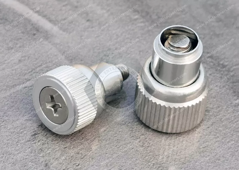
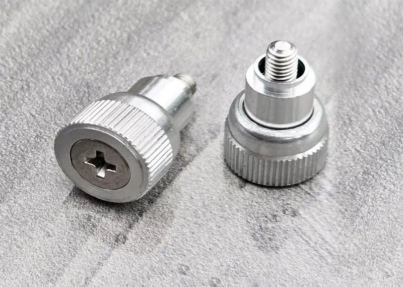
JX-PF11MF and JX-PF12MF are large-knob spring-loaded captive panel screws designed for removable equipment panels requiring convenient access, low installation force and a flush backside.
Their mounting design is particularly suitable for close centerline-to-edge applications and panels where conventional high-force self-clinching installation may be undesirable.
The captive mechanism keeps the screw attached to the panel when disengaged, helping reduce loose hardware during equipment assembly and maintenance.
Key Features
Large knob for convenient manual operation.
Spring-loaded captive screw mechanism.
Universal slot/Phillips drive.
Suitable for close-to-edge panel installations.
Low installation-force mounting design.
Flush backside after proper installation.
Designed for use with panels across a broad range of material hardness, subject to approved mounting requirements.
Referenced Unified threads from #4 to 1/4 inch and metric threads from M3 to M6.
Knurled or smooth metal caps, black metal caps and custom-color plastic cap options.
Material Options
Stainless steel, steel and aluminum are referenced material options. The actual material of each assembly component must be confirmed for the selected configuration.
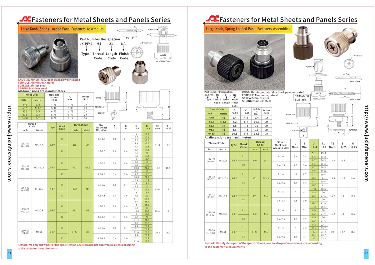
Refer to the product PDF and CAD documentation on pages 51–52 for dimensions, installation requirements and available configurations.
Product Specification
Large-Knob Spring-Loaded Captive Panel Screws – JX-PF11MF / JX-PF12MF
Flush-Back, Low-Installation-Force Fastening Solutions for Industrial Access Panels
JUXIN FASTENERS supplies JX-PF11MF and JX-PF12MF large-knob spring-loaded captive panel screws for industrial equipment manufacturers, enclosure designers and OEM procurement teams.
These captive panel fasteners are intended for applications where convenient manual operation must be combined with close-to-edge mounting, reduced installation force and a flush backside.
The design is particularly relevant where a conventional self-clinching captive screw may impose undesirable installation loads or require more distance between the mounting hole and panel edge.
Unlike loose screws, captive screws remain attached to the access panel when disengaged from the mating thread.
This helps reduce misplaced hardware and supports repeated maintenance access.
Product Overview
Product series: JX-PF11MF and JX-PF12MF
Product category: Large-knob spring-loaded captive panel screws
Primary application: Removable industrial equipment panels
Operating head: Large knob with available knurled cap configurations
Drive type: Universal slot/Phillips
Retention mechanism: Spring-loaded captive screw
Installation concept: Low-force mechanical mounting
Panel positioning: Suitable for close centerline-to-edge applications
Backside profile: Flush after correct installation
Panel compatibility: Broad panel-hardness capability, subject to the specified installation geometry
Referenced Unified threads: #4 through 1/4 inch
Referenced metric threads: M3 through M6
Referenced material families: Stainless steel, steel and aluminum
Cap options: Knurled metal, smooth metal, black metal and custom-color plastic
Technical documentation: Product PDF and CAD drawings, pages 51–52
Custom configurations: Subject to engineering drawing review
The exact dimensional range, mounting geometry, material combinations and individual model differences must be confirmed from the approved drawings.
Close-to-Edge Installation
One of the principal advantages of the JX-PF11MF / JX-PF12MF series is its suitability for mounting locations near the edge of a panel.
In conventional press-installed hardware, installation loads and displaced material can create challenges where the hole is positioned too close to the sheet edge.
These challenges may include panel distortion, local material damage or insufficient retention.
The MF-style mounting concept is intended to address applications where the available edge distance is limited.
However, close-to-edge capability does not mean that any edge distance is acceptable.
The minimum permitted centerline-to-edge distance must be taken from the selected product drawing.
The engineer should also consider panel thickness, material condition and surrounding features.
Low Installation Force
The product series is designed to avoid the high installation forces associated with some conventional self-clinching arrangements.
Lower mounting force may be beneficial for panels that are sensitive to distortion.
It may also be useful where a mounting process must be integrated into an existing equipment assembly line.
The actual installation force depends on the selected part and mounting geometry.
No universal force value should be assumed.
Installation tooling and acceptance criteria should be defined using the approved product documentation.
Panel Hardness Compatibility
The supplied product information describes the series as suitable for installation into panels regardless of hardness.
This should be understood as a design advantage over mounting methods that rely on the fastener being harder than the panel.
It does not mean that every material, thickness or panel construction is automatically suitable.
The panel must still support the required mounting geometry and mechanical retention.
Very thin, brittle, layered or highly flexible panels may require additional evaluation.
The OEM should verify compatibility using representative production materials.
Flush-Back Installation
The series is designed to install flush on the backside of the panel.
This is useful where rear clearance is limited or where projecting hardware could interfere with nearby components.
Flush-back mounting may benefit compact industrial enclosures, tightly arranged electronic equipment and covers positioned close to internal structures.
The engineer must distinguish between the installed backside profile and the external knob projection.
The large knob remains an accessible feature on the operating side.
A flush backside does not imply a completely flush exterior.
The installed assembly should be checked against the available equipment clearance.
Spring-Loaded Captive Screw Function
The spring-loaded mechanism supports controlled movement of the screw during engagement and disengagement.
When the screw is released from its mating thread, the retaining assembly keeps it associated with the mounting panel.
This reduces loose hardware during maintenance.
The spring is not a substitute for adequate thread engagement or joint clamping.
The selected screw must engage the mating thread correctly.
Spring travel, retracted position and working screw length should be verified from the drawing.
Large-Knob Manual Operation
The large knob provides a gripping surface for convenient operation.
Knurled caps can improve finger grip when the panel must be opened or closed repeatedly.
The operating clearance around the knob should be checked during enclosure design.
A larger knob may be preferable for maintenance access but less suitable where external projection must be minimized.
The design engineer should consider the frequency of access and the available operating space.
Universal Slot/Phillips Drive
The supplied product information identifies a universal slot/Phillips drive.
This provides an additional method of operation when manual tightening is insufficient.
The correct screwdriver geometry should be verified against the actual recess.
The OEM should establish an appropriate tightening procedure.
A universal drive designation should not be treated as approval for unrestricted torque.
Mounting Geometry and Panel Preparation
Successful installation depends on the selected product's mounting geometry.
The engineering drawing should define the panel hole, required clearances, installation direction and retention features.
The installation method should not be assumed to be identical to standard press-fit or self-clinching hardware.
Where the approved design uses a mechanically formed retainer, the specified forming or installation procedure must be followed.
The assembly should be inspected to confirm that the retainer is secure and the screw moves freely.
The installation must not damage the panel or restrict the spring-loaded mechanism.
Material Selection
The supplied product information references stainless steel, steel and aluminum.
Because captive panel screws contain multiple components, the material of the screw, retainer, spring and knob may differ.
Material selection should consider strength, corrosion exposure, weight and manufacturing compatibility.
Where required, the customer should specify applicable ASTM, SAE or EN material requirements.
The final material grade and component-level material combination must be confirmed before production.
Surface Finish and Corrosion Considerations
Steel components may require an appropriate protective finish depending on the service environment.
Stainless steel may be considered where corrosion resistance is important.
Aluminum components require evaluation of mechanical properties and compatibility with contacting materials.
For equipment exposed to moisture, cleaning chemicals or outdoor conditions, the complete assembly should be reviewed.
The spring and retainer should not be overlooked during corrosion assessment.
No fixed corrosion rating or environmental service life should be assumed without supporting test results.
Cap and Knob Configurations
The product family references several operating-cap options.
Knurled metal caps provide a textured gripping surface.
Smooth metal caps may be selected for a different operating feel or appearance.
Black metal caps may support industrial equipment styling requirements.
Custom-color plastic caps may be considered for visual identification or product appearance.
Actual cap availability must be confirmed for the selected part number.
Custom colors should be reviewed against the required material, operating environment and order quantity.
Unified Inch Thread Selection
The supplied thread range extends from #4 through 1/4 inch.
ASME B1.1 provides a relevant reference for Unified screw threads.
The exact thread pitch and tolerance class must be specified.
The mating component must use a compatible Unified thread.
Metric Thread Selection
The supplied metric range extends from M3 through M6.
ISO 261 and ISO 965 provide relevant references for metric thread designations and tolerances.
The exact pitch and tolerance class must be confirmed.
Metric and Unified threads are not directly interchangeable.
A nominal size conversion must not be treated as evidence of mechanical interchangeability.
Screw Length and Mating Thread Engagement
The selected screw length must accommodate the complete panel assembly.
Important factors include panel thickness, mating component position and required thread engagement.
The retracted screw position must also be considered.
A screw that is too short may provide insufficient engagement.
A screw that is too long may bottom out or interfere with internal components.
The correct length should be established from the assembly drawing.
Engineering Trade-Off: MF Mounting Versus Conventional Self-Clinching
Conventional self-clinching fasteners depend on compatible panel materials and controlled material displacement.
The JX-PF11MF / JX-PF12MF series is intended for applications where lower installation force and broader panel-hardness compatibility are important.
This can make the MF-style design attractive for selected hard-panel or close-to-edge applications.
However, it may involve different mounting preparation or tooling requirements.
The OEM should compare installation method, retention performance, panel geometry and assembly cost.
The two mounting concepts should not be treated as automatically interchangeable.
Engineering Trade-Off: Flush Backside Versus Rearward Projection
Some panel fasteners extend beyond the rear surface of the panel.
This may create clearance conflicts in compact equipment.
The flush-back design helps reduce this issue.
However, the complete captive assembly still requires appropriate space for screw movement and mating engagement.
The engineer should verify both installed height and operating travel.
Engineering Trade-Off: Large Knob Versus Low-Profile Knob
Large knobs provide convenient hand access.
Low-profile knobs reduce external projection.
For frequently serviced equipment, operating convenience may be a priority.
For compact equipment, available space may be more important.
The selection should be based on the actual maintenance procedure and enclosure geometry.
Engineering Trade-Off: Captive Screws Versus Loose Hardware
Loose screws may have a lower initial purchase cost.
They also avoid some captive mounting operations.
However, they must be handled separately during servicing.
Captive screws remain associated with the panel.
This may reduce misplaced hardware and simplify repeated maintenance.
The OEM should compare the complete assembly and service requirements rather than component price alone.
Industrial Applications
Industrial Control Cabinets
Flush-back captive panel screws may be suitable for removable covers where internal clearance is limited.
Electronic Equipment Enclosures
The retained screw mechanism can help reduce loose hardware during equipment servicing.
Industrial Machinery Covers
Large knobs may provide convenient access to covers opened for inspection or maintenance.
Automation Equipment
Control modules and service panels may benefit from retained fasteners with low-force installation requirements.
Telecommunications Equipment
Equipment housings with limited rear clearance may benefit from flush-back captive mounting.
Test and Measurement Equipment
Instrument covers may use retained screws where regular access is required.
Power Distribution Equipment
Selected service covers may use captive fastening where the equipment's access-control requirements permit hand operation.
Medical and Laboratory Equipment
Serviceable instrument panels may benefit from retained hardware, subject to applicable equipment-specific design and validation requirements.
Engineering Example: Close-to-Edge Control Cabinet Panel
Consider a control cabinet with a narrow removable sheet-metal cover.
The mounting hole must be positioned close to the panel edge.
A conventional self-clinching fastener may require an edge distance or installation force that is difficult to accommodate.
A JX-PF11MF or JX-PF12MF captive panel screw may be considered because the series is intended for close-to-edge and low-force mounting.
The flush backside may also help preserve internal clearance.
Before approving the design, the engineer must confirm the minimum edge distance, hole dimensions, panel thickness, mounting method and screw travel.
The selected configuration should then be tested using representative production panels.
This illustrates why installation geometry should be evaluated before choosing a captive screw solely by thread size.
OEM Procurement and Supplier Qualification
Purchasing teams should identify the complete part configuration rather than requesting only a generic captive screw.
The approved specification should include the model, thread, screw length, mounting geometry, knob configuration, material and finish.
For replacement projects, dimensional comparison is essential.
Similar-looking captive screws may use different mounting methods or retainer dimensions.
Sample evaluation can help verify compatibility before production approval.
RFQ Information
Required model: JX-PF11MF or JX-PF12MF
Unified or metric thread specification
Screw length and spring travel
Knob and cap configuration
Panel material and hardness
Panel thickness
Mounting-hole dimensions
Available centerline-to-edge distance
Required backside clearance
Material and surface finish
Environmental conditions
Estimated order quantity and annual demand
Engineering drawing and revision
Installation and inspection requirements
Packaging and labeling requirements
Providing these details helps JUXIN FASTENERS review the intended configuration and prepare an accurate quotation.
Quality and Functional Verification
A suitable inspection plan may include dimensional checks, thread verification, material confirmation and functional testing.
The screw should remain captive when disengaged.
The spring-loaded mechanism should move smoothly.
The knob should remain securely attached.
The installed retainer should remain stable.
The backside should meet the approved flushness requirement.
The screw should engage the mating thread correctly.
Where required, the OEM may specify retention testing and repeated operation testing.
Acceptance criteria should be established before production.
No fixed retention load, spring force, tightening torque or service-life rating should be assumed without validated data.
Frequently Asked Questions
What are JX-PF11MF and JX-PF12MF?
They are large-knob spring-loaded captive panel screws designed for low-force mounting, close-to-edge applications and flush-back installation.
Can they be used near a panel edge?
The series is intended for close centerline-to-edge applications. The actual minimum edge distance must be confirmed from the approved drawing.
Do they require high installation force?
The product information identifies low installation force as a design feature. The actual force depends on the selected configuration.
Can they be installed in hard panels?
The series is intended for a broad range of panel hardness levels. Material and mounting compatibility must still be verified.
Are they flush on the backside?
The design is intended to provide a flush backside after proper installation.
What thread sizes are referenced?
Unified #4 through 1/4 inch and metric M3 through M6.
Can the knob configuration be customized?
The product information references several metal and plastic cap options, subject to configuration review.
Are custom dimensions available?
Customer-specific requirements can be reviewed using engineering drawings and application details.
Related JUXIN FASTENERS Products
Large-Knob Spring-Loaded Captive Panel Screws – JX-PF11 / JX-PF12 / JX-PF15
For conventional large-knob captive fastening configurations.
Large-Knob Captive Panel Screws – JX-PF13 / JX-PF14
For related large-knob captive fastening applications.
Low-Profile Knob Captive Panel Screws – JX-PF30 / JX-PF31 / JX-PF32
For applications requiring reduced external projection.
Phillips and Six-Lobe Captive Panel Screws – JX-PF50 / JX-PF60
For low-profile captive screws with recessed-drive options.
Standard Spring-Loaded Captive Panel Screws – JX-PFC2 / JX-PFS2
For removable panels requiring standard screw-head operation.
Tool-Only Captive Panel Screws – JX-PFC2P
For concealed-head, tool-operated service access.
Use these descriptive product names as internal-link anchor text and connect them to the corresponding verified JUXIN FASTENERS product pages.
Request a JX-PF11MF / JX-PF12MF OEM Quotation
JUXIN FASTENERS supplies captive panel fastening solutions for industrial equipment manufacturers, enclosure designers, sheet-metal fabricators and international OEM procurement teams.
For JX-PF11MF or JX-PF12MF inquiries, please provide the required thread size, mounting geometry, panel material, edge distance, knob configuration and expected order quantity.
Engineering drawings, annual demand and inspection requirements will help support technical review and quotation preparation.
Email: info@juxinfasteners.com
Website: www.juxinfasteners.com
Product Packaging
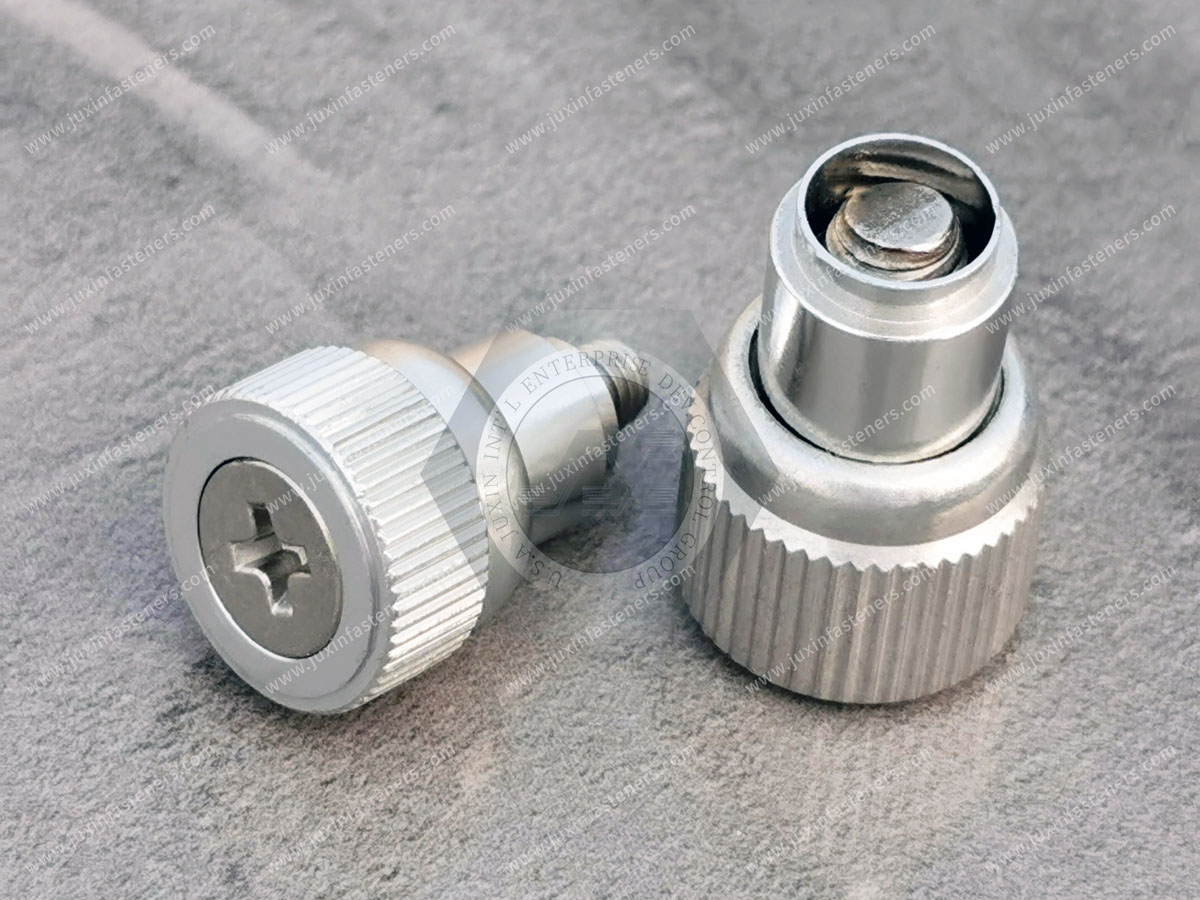
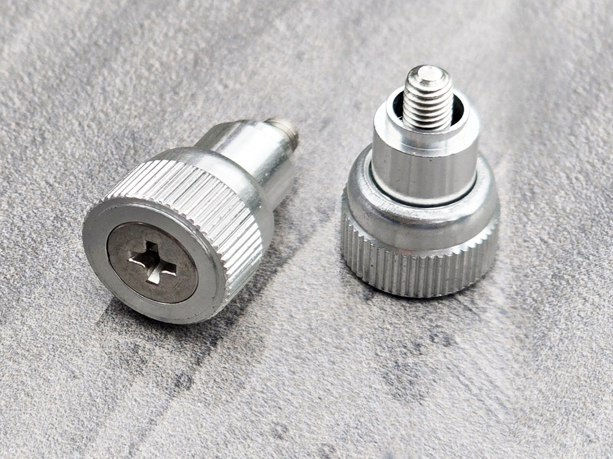
JUXIN FASTENERS provides protective export packaging for JX-PF11MF and JX-PF12MF large-knob spring-loaded captive panel screws.
Standard Packaging
Protective inner packaging may include polybags, foam protection or suitable small boxes, depending on product dimensions and order requirements.
Outer packaging consists of export cartons selected for the shipment.
Palletizing can be arranged for consolidated international shipments when required.
Product Identification
Packaging labels can identify the product model, thread specification, quantity and production batch or lot number.
Customized OEM Packaging
Customer-specific packaging arrangements can be reviewed, including private labels, barcode identification, designated carton quantities, protective separators and pallet configurations.
Final packing quantities, carton dimensions and shipment arrangements will be confirmed according to the approved purchase order and packaging requirements.
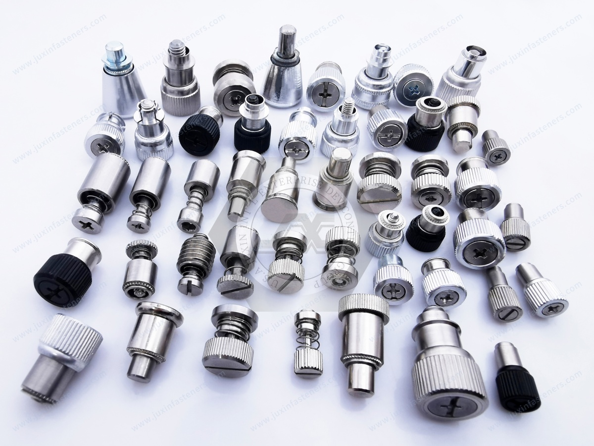
Product Pictures
Contact Us
Tel.:
+86 020 8621 0320
+86 020 3121 6067
E-mail:
Technical Support:
Navigation
SEND INQUIREY