Call Us
+86 136 6007 9809
Call Us
+86 136 6007 9809

Creating a permanent male threaded attachment point in thin sheet metal can be more difficult than the thread itself suggests.
The designer needs sufficient thread length and mechanical retention, but the attachment method must also work with the panel material,
sheet thickness, available installation space, surface finish, dimensional tolerances, manufacturing sequence, and service loads.
Product Specification
Creating a permanent male threaded attachment point in thin sheet metal can be more difficult than the thread itself suggests.
The designer needs sufficient thread length and mechanical retention, but the attachment method must also work with the panel material, sheet thickness,
available installation space, surface finish, dimensional tolerances, manufacturing sequence, and service loads.
Traditional solutions can include welded studs, loose bolts, threaded inserts, brackets, or separate hardware assemblies.
For applications where a mechanically installed male threaded post is preferred, self-clinching studs provide another engineering option.
Also searched as self-clinching threaded studs, press-in studs, sheet metal threaded studs, clinch studs, press-fit threaded studs,
male self-clinching fasteners, and flush-head clinch studs, these components are installed into prepared sheet-metal holes using controlled pressing rather than welding.
They can provide permanent external threads for mounting components, brackets, covers, grounding hardware, electronic modules, electrical assemblies,
and other equipment where the selected stud-and-sheet combination is suitable for the required loads.
However, self-clinching studs should not be treated as universal replacements for welded studs.
The correct fastening architecture depends on:
host sheet material
sheet hardness
sheet thickness
stud thread size
stud length
mounting-hole geometry
available edge distance
required axial load
tightening torque
vibration environment
installation access
corrosion requirements
electrical requirements where applicable
manufacturing sequence
required surface condition
For OEM engineering and procurement teams, these variables should be evaluated as a complete installed system.
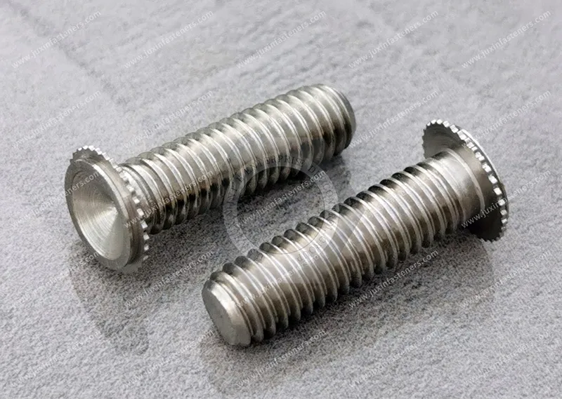
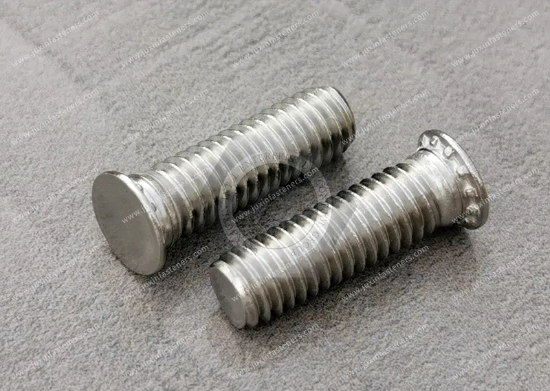
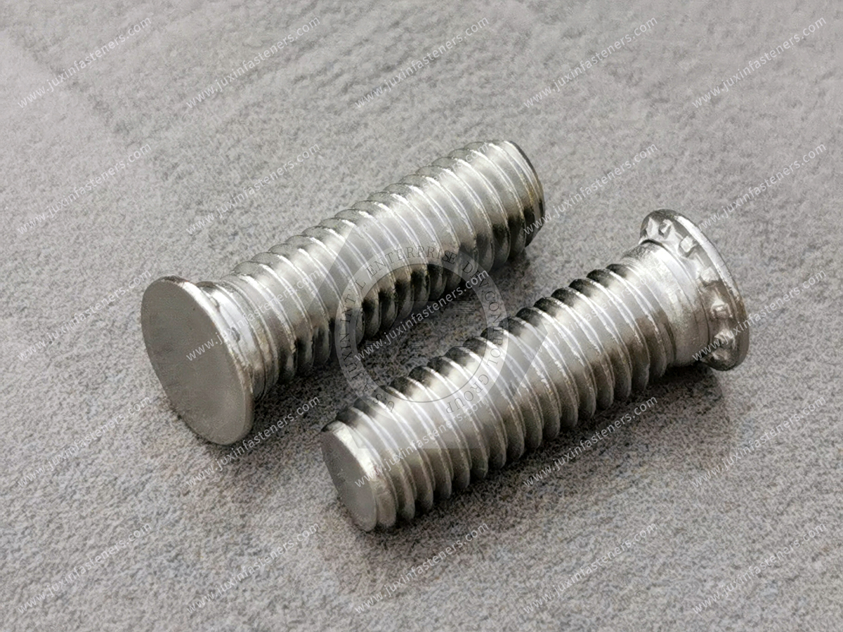
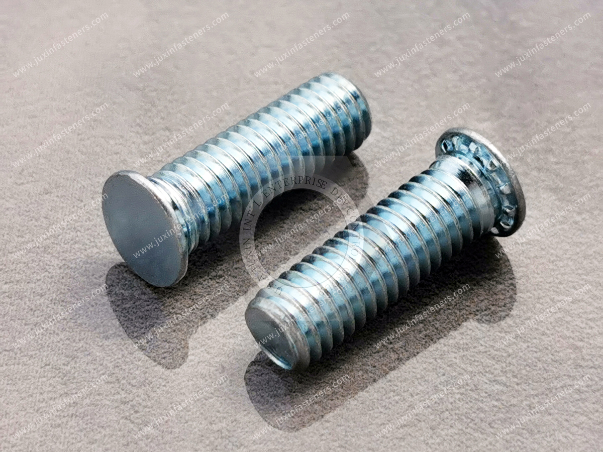
A self-clinching stud is a mechanically installed fastener that creates a permanent male threaded post in suitable sheet material.
A typical design combines:
an external threaded shank
a head or clinching section
an undercut or retention feature
ribs, serrations, knurls, or other anti-rotation geometry depending on design
The stud is positioned in a correctly prepared mounting hole and installed using controlled squeezing force.
During installation, sufficiently ductile host material is displaced into or around the fastener's retention features.
This mechanical interlock helps resist axial displacement.
At the same time, anti-rotation geometry can engage the sheet and help resist stud rotation when a mating nut is tightened or removed.
Depending on the stud design and panel conditions, the installation-side head may be designed to finish flush or near flush with the sheet surface.
This makes self-clinching studs particularly useful when a permanent male thread is required but conventional bolt heads, nuts, or welding operations create packaging or manufacturing problems.
The mechanical performance of a self-clinching stud is produced by the interaction between the fastener and the host sheet.
It should not be attributed to the stud alone.
During controlled press installation, sheet material is displaced into engineered retention features beneath or around the stud head.
The resulting joint may rely on two primary mechanical functions.
Displaced sheet material engages the stud's undercut or retention geometry.
This helps resist forces that attempt to push or pull the stud out of the panel.
Ribs, serrations, knurls, non-round features, or other anti-rotation geometry engage the host material.
This helps resist rotation when torque is applied through the mating nut.
The actual push-out resistance, pull-through behavior, torque-out resistance, and axial load capability depend on the complete installed assembly, including:
stud geometry
stud material and hardness
host sheet material
host sheet hardness
sheet thickness
mounting-hole dimensions
installation force
installation tooling
edge distance
mating hardware
applied load direction
For this reason, performance data from one sheet configuration should not automatically be applied to another.
A common specification mistake is to select a self-clinching stud by thread size and stud length alone.
The host sheet is part of the mechanical joint.
Self-clinching depends on controlled deformation of that sheet.
The sheet must provide sufficient compatible material around the mounting hole to engage the fastener's clinching features.
Potential host materials can include:
cold-rolled steel
suitable stainless steel
aluminum alloys
other ductile sheet materials compatible with the selected fastener design
However, material family alone does not determine compatibility.
Hardness, temper, coating condition, work hardening, thickness, and forming history can all affect clinching behavior.
The correct engineering approach is therefore:
Stud specification + sheet specification + installation process = installed joint
not simply:
Thread size = fastener selection
Self-clinching studs and welded studs can both create permanent male threaded attachment points, but they use fundamentally different joining mechanisms.
A welded stud creates a metallurgical attachment through a welding process.
A self-clinching stud creates a mechanical attachment through controlled deformation of the host sheet.
Neither technology is universally superior.
| Design Consideration | Welded Stud | Self-Clinching Stud |
|---|---|---|
| Attachment principle | Metallurgical joining | Mechanical clinching |
| Heat input | Welding process introduces localized heat | No welding heat is required for clinching |
| Prepared mounting hole | Depends on welding process | Normally required |
| Press access | Not normally required in the same manner | Required for conventional clinch installation |
| Surface-finish considerations | Welding sequence must account for coatings and heat effects | Must account for clinching, coating condition, and installation sequence |
| Sheet compatibility | Depends on welding process and material | Depends on clinching geometry, sheet hardness, ductility, and thickness |
| Stud location | Controlled by welding fixture/process | Primarily controlled by mounting-hole location and tooling |
| Reverse-side condition | Process-dependent | Head condition depends on stud design and installation |
| Retention mechanism | Weld joint | Mechanical interlock |
| Production choice | Suitable where welding is technically and economically appropriate | Suitable where controlled press installation fits the manufacturing process |
The correct decision should therefore consider the entire manufacturing system rather than assuming that a press-in stud automatically replaces a welded stud.
A self-clinching stud may deserve evaluation when:
welding heat is undesirable
a prepared mounting hole can be incorporated into the sheet
press access is available
a flush or controlled head profile is useful
the panel material is suitable for clinching
repeatable stud positioning is important
the assembly is already designed around press-installed hardware
welding is undesirable within the production flow
post-weld cleaning or refinishing would add manufacturing steps
These conditions are common in electronic enclosures, electrical cabinets, server chassis, equipment housings, automotive electronics, and precision sheet-metal assemblies.
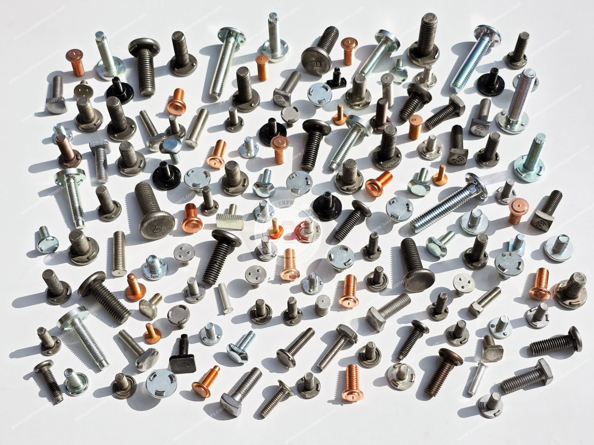
Welded studs remain an important fastening technology.
They may be preferred where:
the structural design is already validated around welding
suitable welding equipment and process controls are available
press access is difficult
the sheet or structural member is unsuitable for clinching
required loads favor the selected welded configuration
the application requires a weld-specific joint architecture
avoiding a prepared clinching hole is advantageous
production economics favor welding
The design decision should therefore be application-specific.
A good supplier should help evaluate whether a self-clinching configuration fits the assembly rather than simply describing it as a universal weld replacement.
One advantage of mechanical clinching is that it does not require a welding arc or weld heat to create the fastener-to-sheet attachment.
This can be relevant when localized welding heat would complicate:
panel flatness
surface appearance
nearby coatings
heat-sensitive adjacent features
dimensional control
downstream finishing
However, this does not mean that any self-clinching stud can automatically be installed into any finished or painted panel.
Coating thickness, paint hardness, plating, powder coating, surface cracking, cosmetic requirements,
and electrical contact requirements may influence whether installation should occur before or after finishing.
The correct manufacturing sequence should be validated for the actual panel and finish system.
Mounting-hole dimensions are critical to clinching performance.
The hole should be produced according to the requirements of the selected fastener.
Important variables can include:
hole diameter
hole tolerance
hole roundness
burr condition
local panel flatness
distance from bends
distance from panel edges
nearby formed features
An oversized hole can reduce engagement.
An undersized hole can interfere with insertion or cause uncontrolled deformation.
Unapproved chamfering, countersinking, or excessive material removal can alter the amount of sheet available to engage the fastener's retention geometry.
The mounting hole should therefore be treated as a controlled fastener interface.
Different sheet-metal manufacturing processes can produce different hole conditions.
Punching may create rollover and burr characteristics.
Drilling produces another edge condition.
Laser cutting can introduce its own dimensional and heat-affected characteristics depending on material and process.
The important issue is not simply which process produced the hole.
The finished mounting hole must meet the dimensional and edge-condition requirements for the selected stud.
For critical production programs, sample installation should use holes produced by the intended production process.
Self-clinching installation requires the host sheet to deform appropriately around the fastener's clinching features.
The relevant hardness relationship is product-specific.
Rather than applying a universal rule to every stud and every material, engineers should compare the actual sheet hardness and condition against the fastener manufacturer's specified installation limits.
This becomes particularly important with:
harder stainless steels
high-strength sheet
work-hardened formed panels
hard aluminum tempers
coated or treated materials
If the sheet does not deform as required, the fastener may not develop the intended mechanical interlock.
Sheet thickness influences:
available material for clinching
installed head condition
push-out performance
torque-out performance
panel distortion
minimum edge distance
suitability of a particular stud geometry
There is no universal minimum sheet thickness for all self-clinching studs.
The allowable range depends on the exact fastener design and application.
OEM engineers should therefore specify the actual panel thickness and tolerance when requesting samples or quotations.
A clinching operation displaces sheet material around the mounting hole.
If the hole is too close to a free edge, bend, cutout, or other geometric discontinuity, the surrounding material may not constrain this deformation in the intended manner.
Possible results include:
local bulging
edge distortion
reduced retention
cosmetic deformation
inconsistent installation
Minimum edge and feature distances should follow the requirements for the selected fastener and should be validated in the actual panel geometry where necessary.
Self-clinching studs are normally installed with controlled squeezing force using suitable press tooling.
A typical installation arrangement supports the panel while providing clearance for the projecting threaded shank.
The tooling must allow the clinching head to seat correctly without damaging the external thread.
Important process variables include:
press force
press stroke
tooling geometry
anvil clearance
tooling alignment
panel support
stud perpendicularity
installation depth
sheet thickness
sheet hardness
More force does not automatically create a stronger joint.
Insufficient installation can leave the fastener incompletely seated.
Excessive force can distort the panel, damage clinching features, or affect the installed geometry.
For volume production, installation settings should be established through controlled trials and monitored according to the manufacturer's quality process.
The external thread is the functional connection interface.
Installation tooling should therefore avoid damaging:
thread crests
thread lead
threaded length
plating
stud end geometry
Anvil or tooling clearance around the projecting stud must be sufficient for the selected thread diameter and stud length.
For automated production, tooling design should also consider stud feeding, orientation, and prevention of thread contact during installation.
A male stud that is not sufficiently perpendicular to its mounting surface can create downstream assembly problems.
These may include:
difficult nut engagement
bracket misalignment
uneven clamping
interference with components
automated assembly problems
The mounting hole, press alignment, tooling, panel support, and fastener geometry all contribute to installed stud orientation.
Perpendicularity requirements should be defined according to the assembly rather than assuming that press installation automatically guarantees a perfect 90-degree stud.
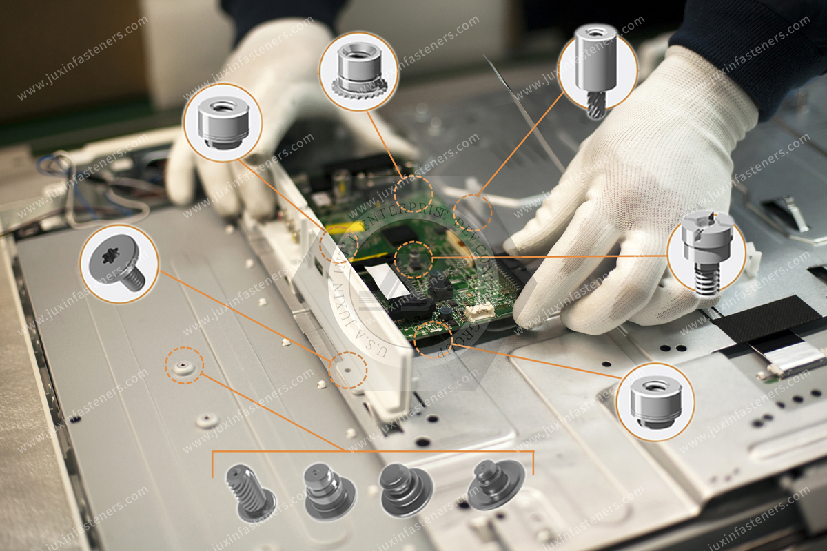
Many self-clinching studs are selected because the head side can provide a low-profile or flush installed condition.
This can be useful on:
exterior enclosure surfaces
chassis side walls
sliding assemblies
mounting interfaces
cosmetic panels
adjacent component surfaces
However, “flush” should be treated as a measurable drawing requirement rather than a marketing description.
The actual installed condition depends on:
stud design
head geometry
sheet thickness
mounting hole
installation depth
tooling
panel material
If surface projection is critical, the permitted condition should be defined and verified on installed samples.
Two commonly discussed performance characteristics are push-out resistance and torque-out resistance.
They represent different loading modes.
Push-out resistance evaluates resistance to axial displacement of the stud from the panel.
Torque-out resistance evaluates resistance to rotation of the stud within the panel.
A stud can perform differently in these two modes.
Both depend on the installed system.
For critical applications, qualification should therefore consider the mechanical mode that actually occurs during assembly and service.
This distinction is particularly important for procurement and design engineers.
The torque applied to a mating nut does not translate directly into the same load at the stud-to-sheet interface.
Joint behavior is influenced by:
thread friction
bearing friction
nut geometry
washer use
lubrication
coating
clamp load
bracket geometry
stud retention
A safe tightening specification should therefore be developed for the complete joint.
A catalog torque-out value should not automatically be treated as the permissible nut tightening torque.
A threaded stud may support:
brackets
modules
busbar hardware
grounding lugs
covers
transformers
electrical components
structural subassemblies
The resulting load path may involve tension, shear, bending, vibration, or combinations of these.
The stud-to-sheet interface is only one part of the load path.
Engineers should also consider:
sheet bending
local bearing
bracket stiffness
nut preload
washer geometry
eccentric loading
vibration
fatigue
edge distance
A larger stud thread does not automatically compensate for a weak host panel.
A useful engineering insight is that the nominal strength of the threaded stud may not be the limiting factor in a thin-sheet assembly.
For example, increasing the stud diameter or selecting a higher-strength stud material may increase the capacity of the fastener itself while providing little benefit if the surrounding sheet deforms first.
The correct design question is therefore:
Where is the weakest link in the complete load path?
Possible limiting locations include:
stud thread
mating nut
stud head
clinching interface
sheet around the mounting hole
sheet edge
bracket
washer bearing area
This is why thin-sheet fastening should be evaluated as an assembly rather than by fastener strength alone.
AI computing infrastructure combines high-density electronics, power distribution, cooling hardware, serviceable modules, and tightly packaged sheet-metal structures.
Potential self-clinching stud applications include:
server chassis
GPU compute systems
power shelves
rack-mounted power equipment
network equipment
storage systems
cooling control equipment
grounding and bonding assemblies
component mounting plates
Self-clinching studs can provide permanent male mounting points where loose bolts would complicate assembly or where welding is undesirable.
For example, a stud installed during chassis fabrication can remain captive to the panel while downstream assembly workers position a component and install only the mating nut.
This can simplify final assembly and reduce loose-hardware handling.
Power shelves and electrical equipment may require threaded posts for mounting:
conductor hardware
terminal components
grounding straps
insulating supports
power modules
brackets
protective covers
When a stud participates in an electrical connection, however, mechanical retention is only part of the design.
The electrical joint may also require evaluation of:
contact resistance
conductive surface condition
plating
clamp load
interface materials
corrosion
thermal cycling
current loading
applicable electrical standards
A mechanically secure self-clinching stud should not automatically be assumed to provide a qualified high-current electrical connection.
Busbar-related searches often include terms such as busbar studs, power terminal studs, grounding studs, and electrical connection posts.
These terms can describe components with very different functions.
A stud used only to mechanically locate a busbar is different from a stud that forms part of the primary electrical current path.
For current-carrying applications, engineers should evaluate:
busbar material
stud material
interface plating
contact area
clamp load
resistance
temperature rise
galvanic compatibility
joint relaxation
thermal cycling
applicable electrical requirements
A self-clinching stud can be considered only after both the mechanical and electrical functions are understood.
Automotive and EV assemblies use sheet-metal structures, electronic modules, brackets, electrical enclosures,
and other components that may require permanent male mounting points.
Potential applications can include:
electronic control modules
battery-management-system enclosures
high-voltage junction boxes
inverter housings
electrical brackets
body electronics
mounting plates
selected grounding or bonding points
Self-clinching studs can be useful where a mechanically installed threaded post fits the panel material, production process, and required performance.
However, automotive applications can involve demanding vibration, fatigue, corrosion, thermal cycling, traceability, and customer-specific validation.
Suitability should be verified for the actual program.
EV battery assemblies combine structural, electrical, thermal, sealing, and safety requirements.
Potential stud applications may occur around:
electronic control housings
BMS brackets
electrical covers
cable-management structures
module-related hardware
serviceable components
A self-clinching stud should not automatically be assumed appropriate for battery tray sealing surfaces, high-voltage current paths, crash-critical joints, or structural battery interfaces.
Those functions require dedicated engineering validation.
The correct product depends on the exact load path and system requirement.
Electrical cabinets, power-conversion equipment, and industrial control systems can require numerous fixed male mounting points.
Applications can include:
inverter enclosures
variable frequency drives
UPS equipment
power conversion systems
motor control centers
industrial control cabinets
energy storage controls
electrical distribution equipment
Self-clinching studs may be used for mounting brackets, electrical devices, grounding hardware, internal structures,
and other components where the selected panel and stud combination provides suitable retention.
Grounding studs are a common search term, but electrical grounding should not be reduced to the presence of a threaded stud.
A grounding or bonding connection may depend on:
conductive interface
coating removal or controlled masking
washer design
terminal lug
clamp load
corrosion resistance
vibration resistance
electrical continuity
applicable equipment standard
If a self-clinching stud is intended for grounding or bonding, the complete electrical joint should be qualified.
Installing a mechanically secure stud into a painted panel does not by itself establish an acceptable electrical ground path.
Telecommunications equipment can contain dense electronics, power systems, RF components, communication modules, and outdoor enclosures.
Potential applications include:
telecom cabinets
network chassis
radio equipment
optical networking systems
base-station power systems
communication equipment racks
Self-clinching studs can provide permanent attachment points for modules, brackets, grounding hardware, and internal structures.
Outdoor applications should additionally consider material and finish selection according to the required corrosion environment.
Industrial automation equipment frequently combines sheet-metal cabinets with control electronics, drives, power supplies, safety equipment, and communication systems.
Potential applications include:
robot control cabinets
machine enclosures
automated production equipment
packaging machinery
material-handling systems
process equipment
control-panel structures
A pre-installed stud can simplify assembly where components must be positioned over fixed mounting points and secured with nuts.
For high-vibration machinery, retention should be evaluated under the actual operating conditions.
Semiconductor manufacturing equipment contains precision mechanical systems, power electronics, control cabinets, instrumentation,
vacuum-related equipment, and complex service modules.
Self-clinching studs may be considered for:
electronic enclosures
mounting brackets
control cabinets
precision sheet-metal panels
service modules
equipment covers
Applications requiring strict cleanliness, corrosion control, or material restrictions should specify those requirements directly in the RFQ.
Commercial HVAC systems contain increasing levels of electronics, power conversion, variable-speed drives, sensors, and control systems.
Potential stud applications include:
control boxes
inverter enclosures
fan-control systems
electrical panels
air-handler control compartments
heat-pump electronics
The appropriate fastener material and finish should be selected according to humidity, condensation, corrosion exposure, temperature, and service requirements.
Medical diagnostic equipment, laboratory systems, and precision instruments may use self-clinching studs in sheet-metal frames and enclosures.
Applications can include:
electronic modules
equipment covers
brackets
internal chassis structures
diagnostic carts
laboratory automation systems
Where medical or regulated equipment requirements apply, fastener selection should be integrated into the OEM's complete material, cleanliness, documentation, and validation process.
The fastener itself does not establish regulatory compliance.
Depending on the fastener design and application, self-clinching studs may be manufactured from materials such as:
carbon steel
stainless steel
other engineered materials where technically appropriate
Material selection should consider:
host sheet material
hardness compatibility
corrosion environment
mechanical load
installation requirements
electrical requirements
customer specification
A material that is suitable mechanically may not automatically be suitable electrically or environmentally.
Possible finish discussions can include:
zinc-based coatings
zinc-nickel systems
passivated stainless steel
other customer-specified surface treatments
The finish can influence:
corrosion resistance
thread dimensions
friction
nut installation behavior
electrical contact
appearance
compatibility with the host assembly
If the stud is used in an electrical joint, the coating should be reviewed as part of the electrical interface rather than solely as corrosion protection.
Self-clinching studs may be required with metric or inch-series external threads.
An RFQ should specify more than nominal diameter.
Relevant thread information can include:
nominal thread size
pitch or threads per inch
threaded length
tolerance or fit class
applicable standard
coating condition
mating nut requirement
Metric thread requirements may reference applicable ISO specifications, while inch-series threads may reference applicable ASME/ANSI specifications according to the customer drawing.
The governing print should control the requirement.
Surface treatment can influence external thread dimensions.
For plated studs, thread acceptance should be evaluated according to the specified thread system and coating condition.
Procurement teams qualifying an alternative source should therefore confirm that the finished, coated fastener meets the required thread fit rather than checking only the uncoated blank.
This is particularly important in automated assembly where inconsistent nut engagement can disrupt production.
Second-source qualification should not be based solely on matching:
M6 × 20 stud
or another nominal thread-and-length description.
A functional-equivalent review should consider:
thread size
pitch
thread tolerance or class
threaded length
overall stud geometry
head diameter
head thickness
clinching feature
undercut geometry
anti-rotation geometry
mounting-hole requirement
compatible sheet thickness
sheet hardness limits
minimum edge distance
installed head condition
material
hardness
surface finish
mechanical retention
installation tooling
Two studs can have identical external threads and still not be interchangeable in the same sheet.
Begin with the current 2D drawing, specification, reference part number, or physical sample.
The objective is to understand the actual functional geometry.
Provide:
material
thickness
hardness where controlled
mounting-hole dimensions
coating
nearby bends
edge distance
required installed surface condition
Specify:
nut type
washer arrangement
tightening requirement
bracket or component being mounted
This helps identify the actual load introduced into the stud.
Review the proposed alternative's clinching and anti-rotation features rather than relying on thread size alone.
Evaluate:
seating
head condition
panel distortion
stud perpendicularity
thread condition
installation repeatability
Depending on the program, this may include:
push-out testing
torque-out testing
tensile testing
tightening trials
vibration testing
corrosion testing
electrical testing where the stud has an electrical function
Only after dimensional, material, installation, and performance requirements have been confirmed should the alternative proceed into production qualification.
Testing a clinch stud in an arbitrary sheet coupon can establish basic feasibility.
It may not reproduce the production assembly.
Production sheet can differ in:
material condition
hardness
thickness tolerance
coating
work hardening
forming history
mounting-hole quality
local stiffness
nearby bends
For important applications, final qualification should therefore use representative production material and manufacturing conditions.
High-volume OEM manufacturing requires more than one successful sample.
The installation process should consistently control:
stud orientation
mounting-hole alignment
press stroke
installation depth
panel support
head seating
thread protection
stud perpendicularity
Manufacturing teams may also need to define inspection criteria for incomplete installation, damaged threads, incorrect orientation, or panel distortion.
A robust installation process converts a fastener design into a repeatable production joint.
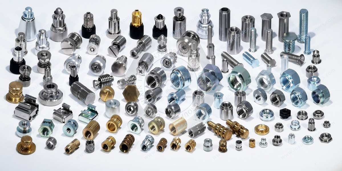
Standard self-clinching studs can satisfy many applications.
Custom development may be appropriate where the project requires:
non-standard thread
special stud length
unusual head geometry
restricted reverse-side profile
special clinching geometry
unusual sheet thickness
non-standard material
special finish
unique anti-rotation requirement
application-specific mounting geometry
For OEM programs, custom development should be evaluated against volume, tooling, qualification cost, and whether an existing standard configuration can satisfy the functional requirement.
A useful sourcing discussion should include questions such as:
Which host sheet materials are compatible with the proposed stud?
What sheet-thickness range applies?
What sheet hardness limits apply?
What mounting-hole dimensions are required?
What edge-distance requirements apply?
What installation tooling is recommended?
What stud materials and finishes are available?
Can you review our existing 2D drawing?
Can samples be provided for installation trials?
Can mechanical test requirements be evaluated in our production sheet?
Can you cross-reference an existing self-clinching stud?
Can you manufacture a custom stud from our drawing?
What inspection and material documentation can be supplied?
What EAU information is required for production pricing?
These questions help procurement compare suppliers on engineering capability as well as unit cost.
For a technically meaningful quotation, provide as much application information as possible.
A self-clinching stud RFQ should include:
2D drawing
3D STEP model where available
existing part number or sample where applicable
thread size
thread pitch or threads per inch
thread tolerance or class
threaded length
overall stud length
head geometry
host sheet material
sheet thickness
sheet hardness where controlled
mounting-hole dimensions
edge-distance constraints
required installed head condition
fastener material
surface finish
corrosion requirement
tightening requirements
push-out requirement where specified
torque-out requirement where specified
axial or shear load requirements where specified
electrical requirements where applicable
sample quantity
prototype quantity
Estimated Annual Usage (EAU)
packaging requirements
documentation requirements
production schedule
Providing the actual host panel and joint requirements helps the supplier determine whether a standard stud is appropriate or whether a drawing-based solution should be evaluated.
Different departments may arrive at the same self-clinching stud project for different reasons.
A design engineer may need a permanent male thread without a loose bolt.
A chassis engineer may need a flush reverse-side surface.
A manufacturing engineer may want to remove a welding operation from a particular sheet-metal assembly.
An electrical engineer may need a controlled mounting or grounding point.
Procurement may need a second source for an existing clinch stud.
Supplier development may need to qualify a functional equivalent against an existing drawing.
These requirements can be translated into a common commercial and engineering path:
Assembly requirement → load and clearance definition → sheet specification → stud geometry selection → drawing review
→ sample installation → mechanical/electrical validation where applicable → supplier qualification → volume sourcing
This process is more reliable than sourcing the component solely by thread size and stud length.
JUXIN FASTENERS supplies engineered self-clinching hardware, self-clinching threaded studs, press-in male threaded fasteners, panel fasteners, and custom fastening components for OEM and industrial applications.
For projects involving self-clinching studs, press-in threaded studs, sheet metal threaded studs, flush-head clinch studs,
or custom male panel fasteners, our team can review customer drawings and application requirements to evaluate the appropriate manufacturing and sourcing path.
Technical review can begin from:
a customer 2D drawing
a 3D model
an existing fastener specification
a physical sample
host-panel information
a functional-equivalent requirement
a new OEM fastening application
Where mechanical performance is important, sample installation and validation using representative production sheet are recommended before final production approval.
Where the stud also performs an electrical function, the electrical interface should be evaluated separately from mechanical retention according to the OEM's applicable requirements.
For drawing review, sample evaluation, functional-equivalent sourcing, custom self-clinching stud development, or production-volume quotation, send your technical requirements to JUXIN FASTENERS.
Email: info@juxinfasteners.com
Website: www.juxinfasteners.com
Product Packaging
Packaging Standard
At Juxin Fasteners, we apply standardized export packaging to ensure product protection, traceability, and compliance with international logistics requirements.
1. Standard Export Packaging
Unless otherwise specified, all products will be packed according to our factory standard export packaging, which includes:
Moisture-resistant inner protection
Poly bag or small box packing as required
Reinforced export cartons
Clear labeling with part number, specification, batch number, and quantity
Palletizing for sea or air shipment when necessary
Our standard packaging is designed to ensure safe transportation, efficient warehousing, and long-distance international shipping.
2. Customized Packaging Options
We also provide customized packaging solutions according to customer requirements, including but not limited to:
Private labeling
Customized barcodes
Specific carton dimensions
Retail packaging
Special pallet configuration
Customer-specific marking and identification
So that you know, customized packaging may involve additional costs and extended lead time depending on the complexity of the requirements.
3. Compliance & Quality Assurance
All packaging processes are controlled under our ISO 9001 quality management system to ensure consistency, traceability, and product integrity throughout the supply chain.
Product Pictures
Contact Us
Tel.:
+86 020 8621 0320
+86 020 3121 6067
E-mail:
Technical Support:
Navigation
SEND INQUIREY