Call Us
+86 136 6007 9809
Call Us
+86 136 6007 9809

Mounting a printed circuit board inside a sheet metal chassis appears simple until the complete mechanical stack is considered.
The PCB must be positioned at the correct elevation above the chassis, mounting holes must align, components and solder joints need adequate clearance,
screws require sufficient thread engagement, connectors must mate correctly, and the board must remain supported during transportation, vibration, assembly, and service.
Product Specification
Mounting a printed circuit board inside a sheet metal chassis appears simple until the complete mechanical stack is considered.
The PCB must be positioned at the correct elevation above the chassis, mounting holes must align, components and solder joints need adequate clearance,
screws require sufficient thread engagement, connectors must mate correctly, and the board must remain supported during transportation, vibration, assembly, and service.
At the same time, electronics manufacturers increasingly need assembly methods that reduce loose hardware and simplify high-volume production.
Traditional PCB mounting architectures may use loose tubular spacers, separate nuts, washers, and machine screws.
These solutions can work effectively, but multi-piece hardware stacks increase component count and can complicate assembly in dense equipment.
For applications where a permanent threaded spacer can be integrated directly into a suitable sheet-metal panel, self-clinching standoffs provide another engineering option.
Also searched as self-clinching threaded standoffs, press-in standoffs, sheet metal standoffs, clinch standoffs, clinch spacers, threaded PCB standoffs,
PCB mounting standoffs, and press-in threaded spacers, these components create a captive spacing and fastening point directly in the chassis.
They are widely evaluated for:
PCB-to-chassis mounting
board-to-board spacing
motherboard support
power electronics mounting
control-board installation
daughter-card elevation
electronic module support
chassis partition spacing
equipment mounting structures
For OEM engineers and procurement teams, however, selecting the correct standoff requires more than specifying a thread size and body length.
The complete assembly should be evaluated.
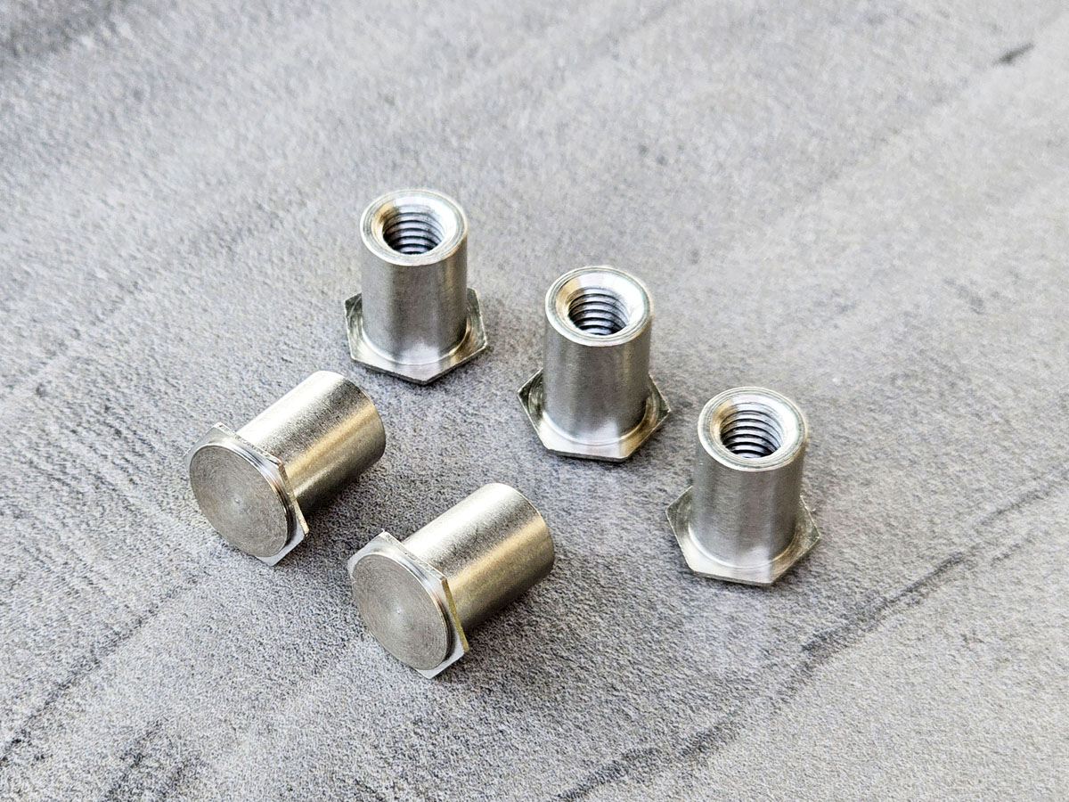
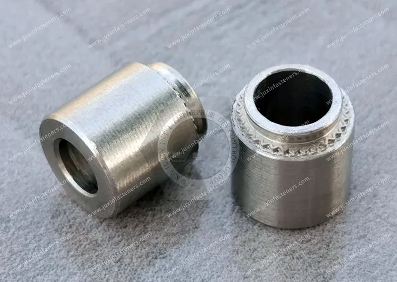
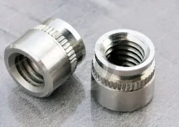
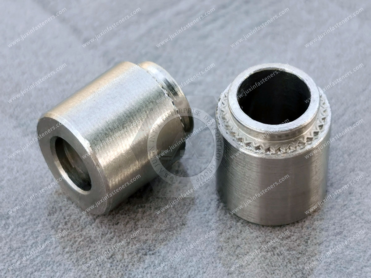
A self-clinching standoff is a mechanically installed spacer designed to create a permanent threaded mounting point at a controlled distance from a sheet-metal surface.
A typical self-clinching standoff combines:
a clinching head or mounting section
an undercut or other retention feature
anti-rotation geometry
a spacer body of defined length
an internal or external threaded interface
Depending on the product design, the threaded portion may be:
thru-threaded
blind-threaded
internally threaded
externally threaded
configured for another application-specific mounting interface
During installation, the standoff is inserted into a correctly prepared panel hole and installed using controlled squeezing force.
The host sheet deforms into or around the fastener's clinching features, creating a mechanical interlock.
Once installed, the standoff becomes captive to the panel and provides both spacing and fastening functions.
A PCB standoff performs several mechanical functions simultaneously.
It can:
establish board elevation
provide a threaded mounting point
transfer clamp load
support the PCB
maintain separation from the metal chassis
help control connector alignment
reduce loose hardware
establish repeatable assembly geometry
The body length is therefore only one parameter.
The complete mounting system also depends on:
PCB thickness
PCB mounting-hole geometry
screw length
screw-head geometry
washer use
component height beneath the PCB
chassis thickness
clinching geometry
sheet flatness
standoff length tolerance
PCB thickness tolerance
connector location
bracket geometry
required electrical clearance
vibration environment
A good PCB mounting design evaluates this complete tolerance and load stack.
Self-clinching standoffs rely on mechanical interaction with the host sheet.
During controlled installation, sufficiently ductile sheet material is displaced into or around the fastener's retention geometry.
This can provide two important forms of resistance.
The clinching interface helps resist forces that attempt to push or pull the standoff out of the panel.
Hexagonal, serrated, knurled, lobed, or other anti-rotation features may engage the host material and help resist rotation when a screw is tightened or removed.
The actual retention performance depends on the complete installed system, including:
standoff geometry
fastener material
fastener hardness
sheet material
sheet hardness
sheet thickness
mounting-hole dimensions
edge distance
installation force
tooling
applied screw torque
external loading
This is why a catalog value from one panel configuration should not automatically be transferred to another material or sheet thickness.
Self-clinching standoffs and loose spacers can both establish PCB elevation, but their assembly architectures are different.
| Design Consideration | Loose Spacer Assembly | Self-Clinching Standoff |
|---|---|---|
| Spacer retention before PCB assembly | Separate component | Captive to panel after installation |
| Hardware count | May require spacer, screw, nut, and washer | Can reduce loose component count |
| Panel preparation | Depends on assembly design | Prepared clinching hole normally required |
| Installation equipment | Conventional hand/assembly tools | Press installation normally required |
| Board installation | May require access to multiple loose components | Board can often be installed from one side after standoff installation |
| Spacer positioning | Controlled during final assembly | Established during chassis fabrication |
| Service handling | Loose components may remain part of architecture | Standoff remains captive to chassis |
| Application suitability | Useful where removable or flexible spacer architecture is desired | Useful where permanent chassis-integrated spacing is desired |
Neither solution is universally better.
The correct architecture depends on production volume, service requirements, panel design, tooling availability, assembly access, and required mechanical performance.
One of the most important selection decisions is whether the standoff should use an open thru-threaded design or a blind-threaded design.
A thru-hole standoff has an internal passage that continues through the body.
Potential advantages include:
flexible screw-length selection
potential for longer screw engagement where geometry permits
visual confirmation of screw penetration in some assemblies
simpler removal of debris from an open passage in some manufacturing processes
However, screw length still requires engineering control.
A screw that extends too far through an open standoff can interfere with:
chassis covers
wiring
neighboring PCBs
moving mechanisms
insulating barriers
adjacent components
“Thru-hole” therefore does not mean screw length is unlimited.
A blind standoff contains a closed end rather than a completely open threaded passage.
Potential reasons for choosing a blind design include:
preventing screw breakthrough beyond the closed end
creating a closed external appearance
separating the screw cavity from the opposite side
controlling available thread depth
protecting adjacent components from excessive screw penetration
However, a closed end should not automatically be described as waterproof, airtight, dustproof, IP-rated, EMI-sealed, or hermetically sealed.
Those are system-level performance claims requiring appropriate design and validation.
This distinction is important for enclosure engineers.
A blind standoff can prevent a screw from passing completely through the component.
That does not establish a qualified environmental seal around the entire installation.
Potential ingress paths may still exist around:
the fastener-to-sheet interface
panel coatings
local sheet deformation
mounting-hole geometry
adjacent enclosure joints
If an enclosure requires IP-rated, water-resistant, dust-resistant, pressure-resistant, or other environmental sealing performance,
the complete assembly should be tested according to the applicable requirement.
A blind standoff should therefore be specified for its mechanical geometry first.
Any sealing function must be separately engineered and validated.
A closed threaded cavity also should not automatically be described as providing EMI or RFI isolation.
Electromagnetic performance depends on the complete enclosure architecture, including:
conductive continuity
apertures
seams
coatings
gaskets
cable penetrations
enclosure geometry
frequency range
grounding and bonding strategy
A blind standoff can change the physical geometry of an enclosure penetration, but EMI/RFI performance should be determined through the OEM's electromagnetic design and validation process.
The nominal standoff body length is often used to establish PCB-to-chassis spacing.
However, the final board elevation is not necessarily equal to the nominal standoff length alone.
The installed assembly can be affected by:
standoff length tolerance
installed seating condition
panel flatness
sheet deformation
PCB thickness
PCB flatness
washer thickness
mounting-pad geometry
screw clamp condition
bracket stack-up
connector constraints
For applications with sensitive connector alignment or mechanical clearance, engineers should calculate the complete dimensional stack rather than specifying only a nominal standoff length.
A more useful design approach is to begin with the required functional clearance.
For example:
Required PCB underside clearance → component keep-out height → manufacturing tolerance → board deflection allowance → chassis tolerance → required standoff geometry
This reverses the common process of selecting an arbitrary standoff length and then checking whether the electronics fit.
The correct question is not:
“Which 10 mm standoff should we buy?”
It is:
“What minimum and maximum PCB-to-chassis clearance must the assembly maintain under the complete tolerance stack?”
The standoff length can then be selected from that requirement.
Modern PCBs can contain components on both sides.
The underside may include:
capacitors
resistors
connectors
solder joints
test points
shielding features
heat spreaders
surface-mount devices
The standoff must provide enough space for the actual underside component envelope plus the required mechanical and electrical clearance.
Designers should also consider:
PCB flex
manufacturing tolerances
chassis distortion
vibration
service loading
Nominal CAD clearance alone may not represent worst-case production conditions.
Mechanical spacing and electrical spacing are related but not identical.
A standoff can physically separate a PCB from a metal chassis, but that does not automatically establish adequate electrical clearance or creepage for the circuit.
Electrical design may depend on:
operating voltage
transient voltage
pollution degree
insulation system
PCB layout
conductive chassis geometry
applicable equipment standards
Where electrical clearance is safety-critical, the required distances should be established according to the governing electrical design requirements.
The mechanical standoff should then support that architecture.
PCB-to-chassis spacing can influence airflow in forced-air-cooled electronics.
However, a self-clinching standoff does not by itself create a guaranteed cooling improvement.
Thermal behavior depends on:
fan architecture
airflow direction
PCB obstruction
component layout
heatsinks
air baffles
cable routing
chassis geometry
pressure drop
heat generation
Standoff height can be one mechanical input into the airflow design.
For high-power equipment, the final thermal effect should be evaluated through the OEM's thermal analysis, CFD, prototype testing, or system validation as appropriate.
Self-clinching standoffs can also be considered in multi-level electronic assemblies where boards, plates, or subassemblies require controlled vertical separation.
Possible applications include:
motherboard and daughter-card structures
power-control boards
communications modules
control-board stacks
sensor electronics
modular equipment platforms
However, a self-clinching standoff requires a suitable host material for its clinching interface.
It should not be confused with PCB broaching fasteners, snap-in PCB spacers, threaded inserts, or conventional board-to-board spacers.
Each technology has a different installation mechanism.
This distinction is particularly important.
Self-clinching fasteners are generally designed to mechanically engage suitable ductile sheet material through controlled material displacement.
Broaching fasteners use a different retention mechanism and may be selected for printed circuit boards or other materials where conventional self-clinching behavior is not appropriate.
A standoff designed to clinch into sheet metal should not automatically be pressed directly into a PCB.
The host material and installation technology must match the fastener design.
Potential host materials can include:
cold-rolled steel
aluminum alloys
suitable stainless steel sheet
other compatible ductile sheet materials
However, the material designation alone is insufficient.
Important variables include:
hardness
temper
work hardening
coating
sheet thickness
forming history
The actual sheet condition should be checked against the selected standoff's installation requirements.
The host sheet must deform appropriately during clinching.
If the sheet is too hard for the selected fastener design, it may not flow into the retention geometry as intended.
Possible consequences include:
incomplete seating
reduced push-out resistance
reduced torque-out resistance
panel distortion
damage to clinching features
Rather than applying one universal hardness rule, engineers should follow the limits specified for the exact fastener design and verify the application when necessary.
Sheet thickness affects the amount of material available to form the mechanical interlock.
It can influence:
push-out performance
torque-out performance
head seating
panel distortion
edge-distance requirements
installation force
There is no universal minimum sheet thickness for every self-clinching standoff.
The correct range depends on the fastener geometry, material, and application.
The mounting hole is a functional part of the clinching system.
Important parameters include:
hole diameter
hole tolerance
roundness
burr condition
panel flatness
edge distance
distance from bends
nearby cutouts
The hole should follow the fastener drawing or supplier installation requirement.
Unapproved chamfering, countersinking, or excessive deburring can alter the amount of sheet material available for clinching.
Mounting holes may be created by:
punching
drilling
laser cutting
other controlled sheet-metal processes
Different processes can produce different edge conditions.
For critical applications, installation trials should use holes produced through the intended production process.
This helps ensure that prototype qualification represents mass-production conditions.
Clinching displaces material around the mounting hole.
If the standoff is installed too close to:
a panel edge
a bend
a large cutout
another fastener
a formed feature
the sheet may not constrain the displaced material in the intended manner.
This can affect:
retention
panel flatness
cosmetic appearance
installation consistency
Minimum feature distances should therefore follow the selected fastener's requirements.
Self-clinching standoffs are normally installed using controlled squeezing force and suitable tooling.
Depending on the standoff geometry, tooling may need to provide clearance around the spacer body while supporting the clinching region.
Important variables include:
press force
press stroke
punch geometry
anvil geometry
tooling alignment
panel support
installation depth
standoff orientation
sheet hardness
sheet thickness
More installation force does not automatically produce better retention.
Insufficient force may produce incomplete seating.
Excessive force can distort the panel or fastener.
The installation process should be established through controlled trials.
A low-profile or flush installed head can be valuable where the opposite side of the sheet must remain clear.
Applications may include:
enclosure exterior surfaces
chassis bottoms
slide interfaces
adjacent module surfaces
cosmetic panels
However, “flush” should be treated as a dimensional requirement rather than an absolute assumption.
Actual installed condition depends on:
head geometry
sheet thickness
mounting hole
installation force
tooling
sheet material
Where protrusion is critical, the acceptable installed profile should be specified on the drawing and validated.
Self-clinching standoffs may use metric or inch-series threads.
The RFQ should identify:
nominal thread size
pitch or threads per inch
applicable thread standard
tolerance or fit class
thread depth
thru or blind configuration
coating condition
Metric requirements may reference applicable ISO thread specifications, while inch-series requirements may reference applicable ASME/ANSI specifications according to the customer drawing.
The governing print should control the final requirement.
For a thru-threaded standoff, screw length should provide sufficient engagement without creating unwanted projection or interference.
The design should consider:
PCB thickness
washer thickness
bracket thickness
thread engagement
available clearance behind the standoff
screw-end geometry
neighboring components
A thru-hole design provides additional screw travel, but this travel is still limited by the surrounding assembly.
Blind-threaded standoffs require more careful screw-length control because internal depth is finite.
The screw must provide adequate thread engagement without bottoming in the blind cavity before the joint is clamped.
A useful engineering relationship is:
Available screw penetration > required thread engagement
while also ensuring:
Actual screw penetration < usable blind thread depth
The exact values depend on:
standoff design
screw end
thread runout
washer stack
PCB thickness
mounting component thickness
manufacturing tolerances
This should be verified from the actual component drawing rather than a universal rule.
One failure mode deserves particular attention in blind standoffs.
If the screw is too long, it can reach the bottom of the blind hole before the PCB or bracket is properly clamped.
The installer may feel increasing torque and assume the joint is tight.
In reality, the torque may be reacting against the bottom of the threaded cavity rather than generating the intended clamp load.
This can result in:
loose PCB support
vibration
connector movement
false torque acceptance
component damage
For blind standoffs, screw-length tolerance and usable thread depth should therefore be part of the joint design.
Torque-out resistance describes the standoff's resistance to rotation within the host sheet.
It should not automatically be interpreted as the permissible screw tightening torque.
Actual screw tightening behavior also depends on:
thread friction
screw material
coating
lubrication
washer
PCB or bracket material
clamp load
thread engagement
standoff retention
The tightening specification should be established for the complete joint.
A PCB is not a structural steel plate.
Excessive screw clamp load can damage:
PCB laminate
plated mounting holes
solder joints
local components
insulating washers
The standoff may be mechanically capable of accepting more torque than the PCB assembly should receive.
Therefore, fastener retention capacity and PCB allowable clamp load should be evaluated separately.
Push-out testing evaluates resistance to axial displacement of the installed standoff.
Results depend on:
standoff geometry
sheet material
sheet hardness
sheet thickness
mounting hole
installation force
tooling
edge distance
For OEM qualification, testing should reproduce the intended production conditions as closely as practical.
Torque-out testing evaluates resistance to standoff rotation within the panel.
This is particularly relevant because repeated screw installation and removal can apply rotational load to the clinching interface.
For serviceable electronics, qualification may need to consider not only initial installation but also repeated maintenance cycles where appropriate.
A tall standoff can behave differently from a short standoff under lateral loading.
As standoff height increases, an off-axis force applied near the top can create a larger bending moment at the base.
This is an important design consideration.
The thread may be identical, and the clinching interface may be identical, but a taller spacer can place a different load on the sheet.
This is one of the most useful distinctions for engineers specifying PCB standoffs.
A longer standoff does more than increase board clearance.
It also changes the mechanical lever arm.
For a lateral force applied at the PCB:
Bending moment at the standoff base increases with the distance between the applied force and the panel.
Therefore, changing from a short standoff to a much taller version should not automatically be treated as a simple dimensional substitution.
The designer should consider:
vibration
PCB mass
connector forces
shock loading
number of mounting points
PCB stiffness
standoff spacing
sheet stiffness
For tall or heavily loaded assemblies, application-specific mechanical validation can be valuable.
High-density AI servers combine large PCBs, accelerator boards, power systems, networking hardware, cooling equipment, and tightly packaged sheet-metal chassis.
Potential self-clinching standoff applications include:
server motherboards
GPU baseboards
power control boards
network boards
management controllers
fan-control electronics
rack power equipment
cooling-control modules
Permanent chassis-integrated standoffs can establish repeatable mounting locations before electronics enter final assembly.
This can reduce loose spacer handling and simplify board installation.
GPU servers can contain large, high-mass boards and multiple supporting structures.
PCB support architecture may need to consider:
board mass
connector loads
heatsink mass
accelerator modules
airflow
service access
chassis vibration during shipping
Self-clinching standoffs can provide fixed support points where their load capacity and host-panel conditions are appropriate.
They should be evaluated as part of the complete board support system rather than as isolated fasteners.
Power shelves, UPS systems, power conversion equipment, and rack-level power hardware may contain:
control boards
sensing electronics
power modules
communication boards
auxiliary electronics
Standoff selection may involve both mechanical clearance and electrical separation requirements.
Where high voltage is involved, electrical creepage and clearance should be established independently according to the applicable equipment requirements.
Telecommunications equipment can require precise board positioning in compact sheet-metal structures.
Potential applications include:
5G equipment
network switches
optical networking systems
telecom power equipment
radio enclosures
outdoor communication cabinets
Self-clinching standoffs can support PCBs, control modules, shielding structures, and other electronics.
For outdoor equipment, corrosion and environmental requirements should be considered alongside mechanical retention.
Blind designs can provide a closed-end thread geometry where desired, but enclosure sealing must still be validated separately.

Power electronics and industrial electrical equipment can use self-clinching standoffs for:
VFD control boards
inverter electronics
UPS control boards
power-conversion controllers
industrial power supplies
protection electronics
monitoring systems
energy storage controls
The standoff provides mechanical elevation while the electrical design determines required insulation and clearance.
Medical and laboratory systems often contain multiple PCBs within serviceable enclosures.
Potential applications include:
imaging systems
diagnostic carts
laboratory analyzers
patient monitoring equipment
control electronics
laboratory automation systems
Captive standoffs can reduce loose hardware during assembly and service.
However, medical-device applications may involve specific material, cleanliness, electrical, documentation, and regulatory requirements.
The standoff itself should not be interpreted as establishing medical compliance.
Automation equipment contains control electronics, drives, sensors, communications hardware, and safety systems.
Potential applications include:
PLC assemblies
robot control cabinets
machine controllers
packaging equipment
automated production systems
industrial instrumentation
Self-clinching standoffs can provide permanent threaded pillars for circuit boards and control modules inside sheet-metal enclosures.
Modern vehicles contain increasing quantities of electronic control hardware.
Potential applications include:
electronic control units
battery management electronics
inverter control boards
onboard charging electronics
infotainment systems
communication modules
sensor electronics
Automotive programs can impose demanding vibration, thermal cycling, corrosion, documentation, and customer-specific qualification requirements.
The actual standoff, panel, installation process, and complete PCB assembly should therefore be validated for the specific program.
Semiconductor manufacturing systems combine precision motion, control electronics, power systems, sensors, and instrumentation.
Self-clinching standoffs may be used in:
control cabinets
instrumentation enclosures
power electronics
equipment modules
serviceable electronics assemblies
Material, cleanliness, corrosion, and dimensional requirements should be defined according to the equipment specification.
Depending on the standoff design and application, available materials may include:
carbon steel
stainless steel
other engineered materials where technically appropriate
Material selection should consider:
host sheet compatibility
hardness
mechanical load
corrosion
temperature
electrical requirements
customer specifications
The correct material should be selected for the complete installed assembly.
Surface treatment may be specified for corrosion protection, appearance, thread behavior, or electrical requirements.
Possible finish discussions may include:
zinc-based coatings
zinc-nickel systems
passivated stainless steel
customer-specified finishes
If the standoff forms part of an electrical grounding or bonding architecture, surface finish should also be evaluated for its effect on electrical contact.
Procurement teams often need to qualify an alternative source for an existing self-clinching standoff.
Matching only:
M3 × 10 standoff
or another nominal thread-and-length description is not enough.
A functional-equivalent review should compare:
thread size
thread pitch
thread tolerance or class
thru or blind design
usable thread depth
standoff body length
body diameter
head geometry
clinching geometry
anti-rotation features
mounting-hole diameter
compatible sheet thickness
sheet hardness limits
edge-distance requirements
installed head profile
material
hardness
surface finish
push-out performance
torque-out performance
installation tooling
Two standoffs with the same thread and body length can require different mounting holes or have different clinching characteristics.
During second-source qualification, standoff body height deserves particular attention.
A small height difference can affect:
connector mating
PCB-to-chassis clearance
shielding contact
heatsink alignment
daughter-card alignment
cable routing
enclosure closure
Therefore, body length should be treated as a functional assembly dimension rather than simply a catalog code.
Provide the current 2D drawing, specification, reference part, or physical sample.
Provide:
material
thickness
hardness where controlled
mounting-hole dimensions
coating condition
edge distance
nearby bends
required reverse-side profile
Provide:
PCB thickness
bracket thickness where applicable
screw size
screw length
washer arrangement
required board elevation
connector alignment requirements
Compare both mounting and spacing geometry.
Check:
seating
panel distortion
standoff perpendicularity
head condition
thread condition
body height
PCB fit
Depending on the program, testing may include:
push-out
torque-out
tightening trials
vibration
shock
corrosion
thermal cycling
repeated service assembly
Install the actual PCB, screws, connectors, and surrounding components.
This step can reveal tolerance-stack issues that fastener-only testing cannot identify.
Production sourcing should follow confirmation of dimensional, material, installation, and performance requirements.
Prototype testing should reproduce the actual production panel where possible.
Production material can differ in:
hardness
thickness tolerance
coating
forming history
work hardening
hole condition
nearby geometry
These differences can influence clinching performance.
Final qualification should therefore use representative production conditions for important applications.
For high-volume electronics production, the standoff should also be evaluated from a manufacturing perspective.
Questions include:
Can the standoff be reliably oriented?
Can installation tooling access the location?
Is sufficient support available beneath the panel?
Can installation depth be controlled?
Can damaged or incomplete installations be detected?
Can the PCB be lowered onto all standoffs without interference?
Can screws be installed with automated or powered tools?
Are service screws accessible after final assembly?
Good fastening design supports both engineering performance and production efficiency.
Standard standoffs satisfy many PCB and chassis applications.
Custom development may be appropriate where the application requires:
non-standard body height
unusual thread
special blind-thread depth
special head geometry
restricted external profile
unique mounting-hole requirements
special material
special finish
application-specific body diameter
unusual electrical or mechanical clearance
integration with a custom chassis architecture
For OEM programs, custom development should be evaluated against expected volume, tooling requirements, qualification cost, and whether a standard component can meet the functional requirement.
Useful sourcing questions include:
Which host sheet materials are compatible?
What sheet-thickness range applies?
What sheet-hardness limits apply?
What mounting-hole dimensions are required?
What minimum edge distance applies?
Is the thread thru-hole or blind?
What is the usable thread depth?
What body-height tolerances are available?
What installation tooling is recommended?
What materials and finishes are available?
Can the supplier review an existing 2D drawing?
Can samples be provided for production-sheet testing?
Can a functional equivalent be evaluated?
Can custom standoffs be manufactured from drawings?
What inspection and material documentation can be supplied?
What EAU information is required for volume pricing?
These questions allow procurement to compare suppliers based on functional compatibility rather than unit price alone.
A complete RFQ reduces clarification cycles and helps the supplier evaluate the correct standoff architecture.
For self-clinching standoffs, press-in threaded spacers, PCB mounting standoffs, or custom sheet-metal spacers, provide as much of the following information as possible:
2D drawing
3D STEP model where available
existing part number or physical sample
host sheet material
sheet thickness
sheet hardness where controlled
mounting-hole diameter and tolerance
required standoff body height
body-height tolerance
thru-hole or blind-thread requirement
usable blind thread depth where applicable
internal or external thread
thread size
thread pitch or threads per inch
thread tolerance or fit class
PCB thickness
bracket thickness where applicable
screw size and length
required board-to-chassis clearance
required installed head profile
fastener material
surface finish
corrosion requirement
operating temperature
mechanical retention requirements
vibration or shock requirements where applicable
electrical requirements where applicable
sample quantity
prototype quantity
Estimated Annual Usage (EAU)
packaging requirements
inspection and documentation requirements
production schedule
The more accurately the supplier understands the panel, PCB, screw, spacing requirement, and operating environment, the more meaningful the proposed solution will be.
Different engineering and sourcing teams may enter the project from different directions.
An electronics packaging engineer may need more clearance beneath a PCB.
A mechanical engineer may need a precise connector elevation.
A chassis engineer may want to remove loose spacer hardware.
A manufacturing engineer may want faster board installation.
A procurement manager may need a second source for an existing self-clinching standoff.
A supplier-development team may need to qualify a functional equivalent against an existing print.
These requirements can be translated into a common sourcing path:
Functional PCB clearance → tolerance stack → host sheet specification → standoff architecture → screw/thread review
→ drawing review → sample installation → assembly validation → supplier qualification → volume sourcing
This approach creates a stronger engineering and commercial foundation than sourcing a standoff solely by thread size and nominal length.
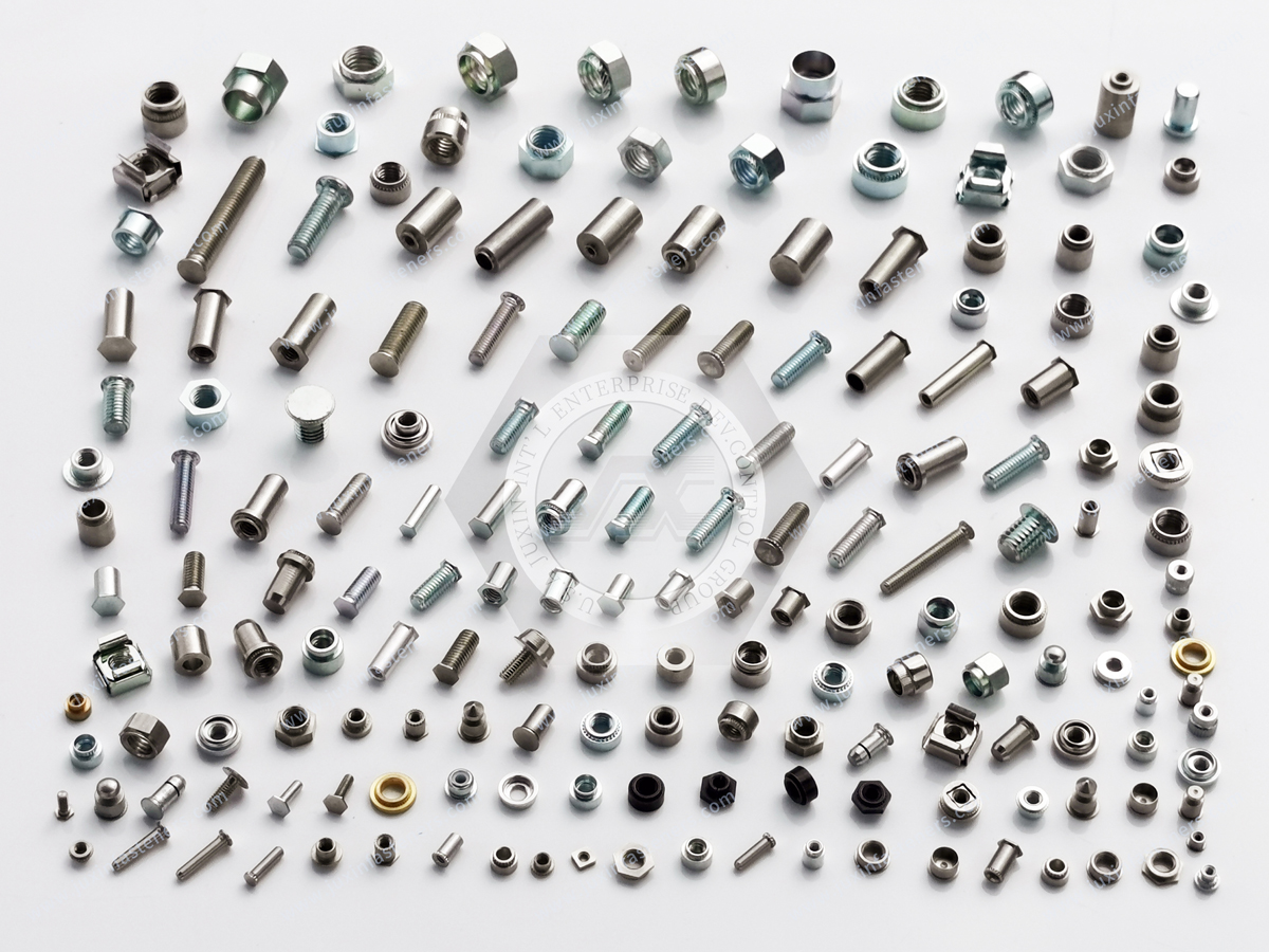
JUXIN FASTENERS supplies engineered self-clinching hardware, self-clinching threaded standoffs, blind standoffs, thru-hole standoffs,
press-in threaded spacers, panel fasteners, and custom fastening components for OEM and industrial applications.
For projects involving self-clinching standoffs, PCB mounting standoffs, sheet metal standoffs, blind threaded standoffs, press-in spacers,
or custom electronics mounting hardware, our team can review customer drawings and application requirements to evaluate the appropriate manufacturing and sourcing path.
Technical review can begin from:
a customer 2D drawing
a 3D model
an existing fastener specification
a physical sample
host-panel information
PCB and screw stack-up information
a functional-equivalent requirement
a new OEM electronics packaging application
Where retention or dimensional performance is important, sample installation and validation using representative production sheet and the actual PCB assembly are recommended before final production approval.
For drawing review, sample evaluation, functional-equivalent sourcing, custom self-clinching standoff development, or production-volume quotation, send your technical requirements to JUXIN FASTENERS.
Email: info@juxinfasteners.com
Website: www.juxinfasteners.com
Product Packaging
Packaging Standard
At Juxin Fasteners, we apply standardized export packaging to ensure product protection, traceability, and compliance with international logistics requirements.
1. Standard Export Packaging
Unless otherwise specified, all products will be packed according to our factory standard export packaging, which includes:
Moisture-resistant inner protection
Poly bag or small box packing as required
Reinforced export cartons
Clear labeling with part number, specification, batch number, and quantity
Palletizing for sea or air shipment when necessary
Our standard packaging is designed to ensure safe transportation, efficient warehousing, and long-distance international shipping.
2. Customized Packaging Options
We also provide customized packaging solutions according to customer requirements, including but not limited to:
Private labeling
Customized barcodes
Specific carton dimensions
Retail packaging
Special pallet configuration
Customer-specific marking and identification
So that you know, customized packaging may involve additional costs and extended lead time depending on the complexity of the requirements.
3. Compliance & Quality Assurance
All packaging processes are controlled under our ISO 9001 quality management system to ensure consistency, traceability, and product integrity throughout the supply chain.
Product Pictures
Contact Us
Tel.:
+86 020 8621 0320
+86 020 3121 6067
E-mail:
Technical Support:
Navigation
SEND INQUIREY