Call Us
+86 136 6007 9809
Call Us
+86 136 6007 9809

Self-Clinching Standoffs for Electronics Enclosures: PCB Mounting, Sheet Metal Design and OEM Installation
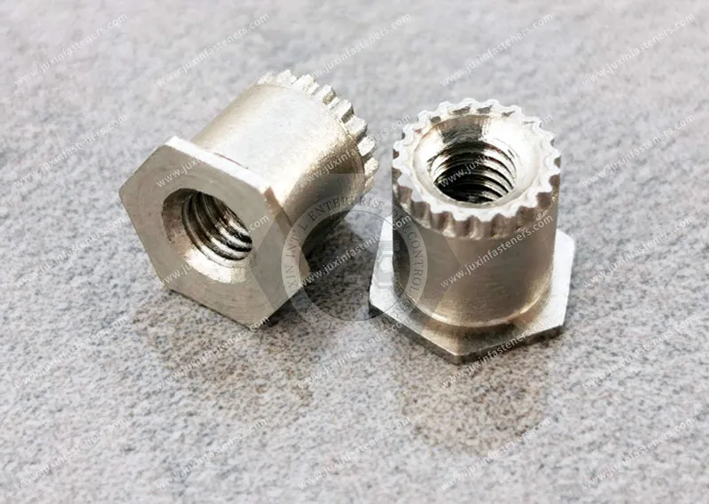
Self-clinching standoffs provide permanent threaded mounting points and controlled spacing in suitable sheet metal assemblies.
They are widely considered for printed circuit board mounting, server chassis, telecommunications equipment, power electronics housings, electrical cabinets, and precision industrial enclosures.
Product Specification
Self-clinching standoffs provide permanent threaded mounting points and controlled spacing in suitable sheet metal assemblies.
They are widely considered for printed circuit board mounting, server chassis, telecommunications equipment, power electronics housings, electrical cabinets, and precision industrial enclosures.
In compact electronic equipment, maintaining the correct distance between a PCB and its supporting metal panel is essential for mechanical clearance,
component protection, assembly accessibility, and repeatable manufacturing.
Conventional loose spacers may require additional handling and alignment during assembly.
Self-clinching standoffs can eliminate some of these operations by installing the spacing component directly into the supporting sheet.
However, a reliable self-clinching standoff installation requires more than selecting the correct thread size and nominal height.
The design must account for the host sheet material, minimum sheet thickness, hardness, mounting-hole geometry, edge distance,
installation tooling, mechanical retention, and the actual PCB assembly requirements.
JUXIN FASTENERS supplies self-clinching standoffs and related industrial fastening components for drawing-based OEM applications.
This guide explains how to select self-clinching standoffs for electronic enclosures, compare blind and through-threaded designs,
evaluate sheet metal installation limits, and specify components for consistent industrial production.
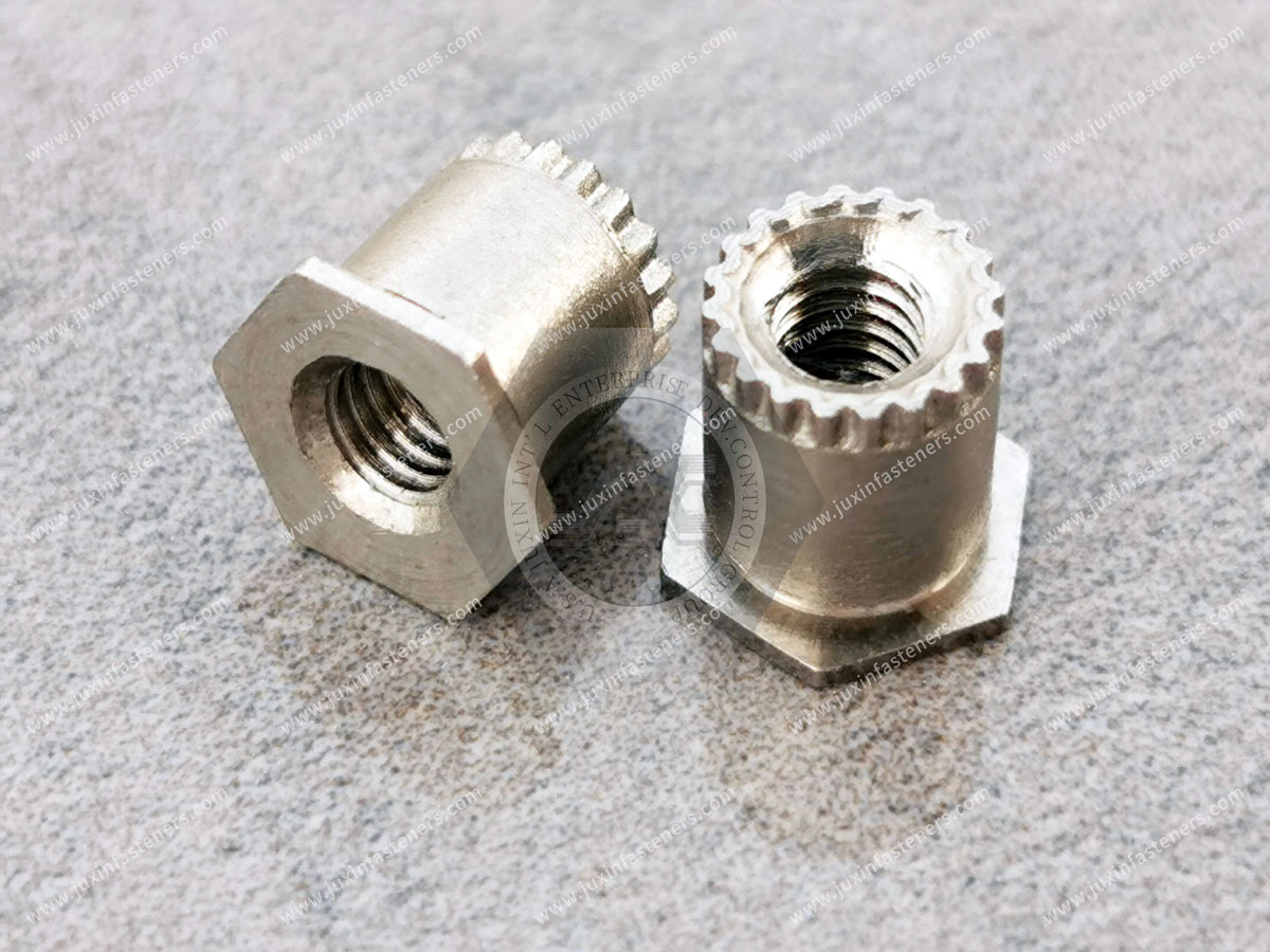
A self-clinching standoff is a fastening component designed to create a permanent mounting feature and a defined spacing distance from a suitable sheet metal surface.
Depending on the product configuration, the standoff may provide an internal threaded hole, a blind internal thread, or another specified mounting feature.
During installation, controlled pressing force causes the surrounding sheet material to engage with the standoff's retention geometry.
Many conventional self-clinching designs rely on plastic deformation of the host sheet into an undercut or related feature.
This mechanical engagement helps retain the standoff in the sheet.
A conventional loose spacer is positioned between components during assembly and generally depends on a separate fastener to remain in place.
A self-clinching standoff is installed into the supporting sheet before final assembly.
This distinction may provide manufacturing advantages:
Reduced handling of loose hardware.
Repeatable standoff positioning.
Defined mounting height.
Simplified subsequent assembly operations.
Compatibility with suitable press installation processes.
Potential reduction in assembly errors.
These benefits depend on the selected component and production process.
A self-clinching nut primarily provides an internal thread in sheet metal.
A self-clinching standoff provides a mounting feature at a specified distance from the sheet surface.
The required height and clearance therefore become additional critical dimensions.
Two important configurations are through-threaded and blind-threaded standoffs.
The correct choice depends on the screw engagement requirements, assembly geometry, and clearance behind the mounting feature.
A through-threaded standoff has an internal thread extending through the body, according to the selected design.
Potential applications include:
PCB mounting.
Electronic module installation.
Server chassis assemblies.
Industrial control equipment.
Mechanical brackets.
Equipment mounting structures.
Through-threaded designs may provide flexibility in screw engagement where sufficient clearance is available.
However, the mating screw must not interfere with components beyond the threaded opening.
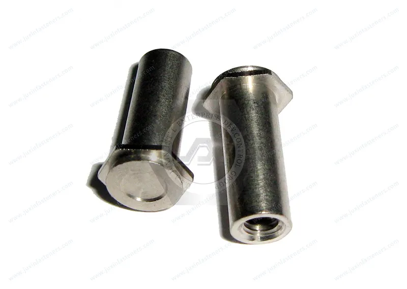
A blind-threaded standoff contains an internal thread that does not extend completely through the component.
This configuration may be selected when the design requires a defined internal thread depth or limits screw penetration beyond the standoff.
Potential applications include:
Compact electronic assemblies.
Equipment with restricted backside clearance.
PCB mounting arrangements.
Precision mechanical housings.
A blind-threaded standoff should not automatically be considered waterproof, airtight, or suitable for contamination control.
The actual closure geometry, installation interface, and sealing requirements must be evaluated.
| Selection Factor | Through-Threaded Standoff | Blind-Threaded Standoff |
|---|---|---|
| Internal thread | Extends through the component | Terminates within the component |
| Screw penetration | Depends on available clearance | Limited by usable internal depth |
| PCB mounting | Suitable for compatible designs | Suitable for compatible designs |
| Screw bottoming risk | Possible interference beyond the standoff | Possible bottoming within the blind hole |
| Thread engagement | Depends on component length and geometry | Depends on usable blind-thread depth |
| Sealing performance | Not inherently sealed | Not inherently certified as sealed |
| Inspection | Through-thread access may simplify some checks | Requires attention to internal thread depth |
Specify the required thread depth and mating screw length rather than choosing a configuration solely from its external appearance.
The mounting height of a self-clinching standoff is a functional dimension.
It determines the nominal spacing between the supporting panel and the mounted component.
For electronic assemblies, incorrect spacing may cause mechanical interference, board deformation, or assembly difficulty.
Engineers should evaluate:
Components mounted on the underside of the PCB.
Solder joints and solder protrusions.
Conductive features.
Connectors.
Cable routing.
Nearby structural parts.
Insulation requirements.
Thermal expansion.
Assembly tolerances.
The standoff height should be selected according to the complete assembly geometry.
A standoff may provide sufficient physical separation while the electrical clearance remains inadequate for the equipment's operating voltage or environmental conditions.
Where electrical safety requirements apply, the complete design must satisfy the relevant equipment specification.
A metal standoff does not independently establish electrical insulation.
The nominal standoff height alone is insufficient for precision assemblies.
Engineers should consider:
Height tolerance.
Installed height.
Perpendicularity.
PCB thickness variation.
Sheet metal flatness.
Multiple mounting-point alignment.
For assemblies using several standoffs, variation in installed heights may introduce bending stresses when the PCB is secured.
A PCB mounted on multiple standoffs may experience unintended stress if the mounting points are not sufficiently coplanar.
Production drawings should identify critical dimensions and inspection requirements where necessary.
Self-clinching performance depends on the interaction between the standoff retention geometry and the parent sheet material.
The host sheet must be compatible with the intended installation mechanism.
Aluminum is widely used for lightweight equipment housings and electronic enclosures.
However, aluminum alloys and tempers have different hardness and forming characteristics.
The selected standoff must be suitable for the actual alloy and material condition.
Cold-rolled steel is commonly used in server chassis, telecommunications cabinets, electrical enclosures, and industrial equipment.
Material specifications may include appropriate grades under EN 10130 or ASTM A1008/A1008M.
Compatibility depends on the actual material grade, hardness, thickness, and selected standoff.
Stainless steel sheet may require specialized self-clinching designs because conventional clinching components are not universally suitable for harder parent materials.
A stainless steel standoff should not automatically be assumed compatible with stainless steel sheet.
The required hardness relationship and product-specific installation conditions must be verified.
During installation, the surrounding sheet material must deform sufficiently to engage with the standoff's retention features.
If the sheet is too hard, incomplete material flow may occur.
Potential consequences include:
Reduced push-out resistance.
Reduced torque-out resistance.
Incomplete seating.
Local deformation.
Installation difficulty.
No single Rockwell hardness limit applies to all self-clinching standoffs.
Permitted hardness depends on the specific product design and material combination.
The allowable hardness must be confirmed from the applicable standoff specification.
The minimum host sheet thickness is another essential design requirement.
The sheet must provide sufficient material for the standoff's retention geometry to engage properly.
If the sheet is thinner than the specified minimum, the installation may not achieve the intended mechanical retention.
Potential problems include:
Insufficient material engagement.
Reduced axial retention.
Reduced rotational resistance.
Sheet distortion.
Incomplete installation.
Self-clinching standoffs are available in different geometries and installation configurations.
Their minimum thickness requirements are not necessarily identical.
Some designs are intended for particularly thin sheet metal, while others require thicker material.
A general range such as 1.0–3.2 mm should not be treated as a universal specification.
Sheet metal is normally supplied with manufacturing tolerances.
A nominal thickness does not guarantee that every location on the sheet has exactly that dimension.
The selected standoff should remain compatible with the permitted actual thickness range.
Forming operations may alter the sheet geometry and local material condition.
Standoffs installed near formed features require additional evaluation.
Correct mounting-hole geometry is essential for self-clinching standoff performance.
The receiving hole must match the selected product's installation requirements.
Each standoff design may require a specific hole diameter and tolerance.
An oversized hole may reduce the amount of material available for clinching.
An undersized hole may prevent correct insertion or cause unwanted deformation.
Do not apply a universal hole tolerance to all self-clinching standoffs.
Punching is commonly used in sheet metal production.
The resulting hole quality depends on:
Punch geometry.
Die clearance.
Tool wear.
Sheet material.
Burr formation.
Hole roundness.
The manufacturing process should maintain the approved hole dimensions.
Laser cutting may be used for suitable sheet metal components.
However, laser-cut edges may differ from punched edges in geometry, surface condition, and local thermal effects.
The selected standoff must be qualified for the actual hole preparation process.
The direction and condition of the hole burr can influence installation.
The correct installation side should follow the applicable product instructions.
Mounting-hole position is particularly important when multiple standoffs support one PCB or electronic module.
Position variation can cause misalignment and assembly stress.
Important checks may include:
Diameter.
Roundness.
Position.
Burr condition.
Sheet thickness.
Local flatness.
A self-clinching standoff requires sufficient surrounding sheet material to develop the intended retention.
If the mounting hole is too close to an edge or formed feature, the sheet may deform during installation.
Insufficient edge distance may cause:
Sheet bulging.
Local cracking.
Reduced retention.
Distorted edges.
Visible surface defects.
Bends may affect material condition, local geometry, and tooling access.
The standoff must be positioned to allow proper press installation.
Closely spaced mounting holes may influence local sheet stiffness and deformation.
Engineers should consider the combined geometry rather than evaluating each hole independently.
The minimum permitted distance must follow the selected product's specifications.
A universal edge-distance multiplier should not replace product-specific engineering data.
Self-clinching standoffs generally require controlled pressing force.
The equipment must apply suitable force while maintaining correct alignment.
Many conventional designs are installed using a controlled squeezing action between appropriate tooling surfaces.
Proper alignment helps achieve consistent material flow and seating.
Hydraulic presses may be suitable for certain standoff installation processes.
The equipment must provide appropriate force, alignment, and tooling support.
Pneumatic presses may also be suitable where their available force and control characteristics meet the installation requirements.
Servo-controlled equipment may provide programmable force and displacement control.
For suitable high-volume manufacturing processes, this can support repeatable installation and process monitoring.
The required installation force depends on:
Standoff geometry.
Sheet material.
Sheet hardness.
Sheet thickness.
Hole dimensions.
Tooling.
There is no universal installation force for all self-clinching standoffs.
Insufficient force may produce incomplete clinching engagement.
Excessive force may distort the sheet, damage the standoff, or affect thread functionality.
Important considerations include:
Punch geometry.
Anvil geometry.
Thread protection.
Workpiece support.
Fastener alignment.
Tool clearance.
Installation direction.
Tooling should follow the selected product's installation requirements.
Mechanical retention is a critical aspect of self-clinching standoff performance.
Two commonly evaluated characteristics are push-out resistance and torque-out resistance.
Push-out resistance describes the axial force required to displace an installed standoff from the parent sheet under defined test conditions.
The measured value depends on the test configuration.
Factors influencing push-out resistance include:
Sheet material.
Sheet thickness.
Hole dimensions.
Retention geometry.
Installation conditions.
Torque-out resistance describes the resistance of the installed standoff to rotation relative to the parent sheet.
It is important when tightening or removing the mating screw.
Thread strength is separate from retention in the sheet.
A standoff may remain securely clinched while the internal thread or mating screw becomes the limiting element.
Tall standoffs may experience bending moments when lateral loads are applied to the mounted component.
The resulting loads must be evaluated according to the actual assembly geometry.
Push-out and torque-out results do not independently establish the complete assembly's mechanical capacity.
Engineers must also consider:
Screw strength.
Thread engagement.
Standoff height.
Sheet stiffness.
Applied loads.
Vibration.
Thermal effects.
PCB support geometry.
Correct screw selection is essential for reliable PCB mounting.
The mating screw must engage sufficiently with the standoff's internal thread.
The required engagement depends on the thread size, material, and joint loading.
In a blind-threaded standoff, the screw may contact the internal end of the hole before the assembly is fully clamped.
This can produce misleading tightening behavior or damage.
In a through-threaded design, excessive screw length may cause interference with nearby components.
Screw length selection should consider:
PCB thickness.
Washer thickness, where used.
Bracket thickness.
Standoff height.
Thread engagement.
Available clearance.
Tightening torque must be appropriate for the screw, standoff thread, and complete assembly.
An excessive torque can damage threads or overload the clinching interface.
A universal tightening torque should not be assigned solely from nominal thread size.
Self-clinching standoffs are often used in electrical and electronic equipment.
However, mechanical fastening and electrical grounding are different engineering functions.
A metal standoff may form part of an electrical bonding path in a properly designed assembly.
Actual conductivity depends on:
Materials.
Surface coatings.
Contact pressure.
Oxidation.
Installation condition.
Joint geometry.
Zinc plating, stainless steel surface condition, and other finishes can influence electrical contact behavior.
A particular coating should not automatically be described as suitable for grounding without appropriate validation.
Where a standoff forms part of a protective bonding or grounding system, the complete assembly must satisfy the applicable electrical requirements.
Mechanical push-out or torque-out testing alone does not verify electrical continuity.
If electrical isolation is required, a conductive metal standoff may not be appropriate without additional insulating components.
The complete mounting design must address the required insulation characteristics.
Material selection affects mechanical performance, corrosion behavior, and installation compatibility.
Carbon steel is commonly used in industrial fastening applications.
Suitable coatings may be specified for corrosion protection.
Stainless steel may be selected for certain corrosion-resistant applications.
However, stainless steel fastener material does not automatically establish compatibility with a stainless steel host sheet.
Aluminum components may be considered for selected lightweight applications.
Their suitability depends on material properties, geometry, and installation requirements.
Zinc plating may provide corrosion protection for suitable carbon steel components.
Coating thickness and dimensional requirements should be defined.
Other finishes may be considered according to the application.
Availability and compatibility must be confirmed for the specific product.
Dissimilar metals may create galvanic corrosion risks in the presence of moisture or other electrolytes.
The material combination should be evaluated according to the service environment.
Server chassis and AI data center infrastructure often use precision sheet metal assemblies with multiple internal mounting points.
Potential applications include:
Server chassis.
Electronic module supports.
Power supply housings.
Equipment control assemblies.
Internal mounting brackets.
PCB supports.
Networking equipment.
Engineers should consider:
Compact mounting geometry.
PCB clearance.
Standoff height.
Installation access.
Sheet metal compatibility.
Serviceability.
Assembly repeatability.
Electronic equipment may experience local temperature changes during operation.
Thermal expansion and material compatibility should be considered where relevant.
High-volume chassis production may benefit from controlled press installation and repeatable component dimensions.
However, the actual installation process must be qualified for the selected standoff.
Telecommunications equipment often requires compact mechanical assemblies and precise electronic module positioning.
Self-clinching standoffs may be used in:
Telecommunications cabinets.
Network equipment housings.
Electronic control modules.
Equipment support panels.
Internal mounting structures.
Selection should consider:
Mechanical clearance.
Mounting accuracy.
Corrosion exposure.
Vibration.
Service access.
Electrical requirements.
Where multiple standoffs support a single assembly, positional accuracy is particularly important.
Self-clinching standoffs may be suitable for selected mechanical mounting applications in power electronics and electrical equipment.
Potential applications include:
Power supply housings.
UPS equipment.
Industrial control cabinets.
Power conversion equipment.
Electrical enclosures.
Equipment mounting brackets.
Important factors include:
Operating temperature.
Electrical clearance.
Mechanical loading.
Sheet metal thickness.
Installation access.
Corrosion environment.
Maintenance requirements.
The standoff must not be assumed to satisfy electrical safety requirements independently of the complete equipment design.
Industrial automation equipment often requires reliable internal mounting points for controls, sensors, and electronic modules.
Self-clinching standoffs may provide suitable spacing and fastening features in fabricated metal panels.
Potential benefits include:
Reduced loose-part handling.
Repeatable positioning.
Defined mounting heights.
Compatibility with suitable automated assembly.
Simplified final equipment assembly.
Engineers must verify the standoff's mechanical capacity under the actual loading conditions.
A self-clinching standoff intended for PCB support should not automatically be used as a structural support for heavy mechanical equipment.
Possible causes:
Oversized mounting hole.
Insufficient installation force.
Incorrect sheet material.
Incomplete clinching engagement.
Excessive tightening torque.
Recommended review:
Check the product drawing, mounting hole, sheet material, installation process, and screw tightening requirements.
Possible causes:
Insufficient sheet thickness.
Incorrect retention geometry.
Incomplete installation.
Parent sheet damage.
Excessive axial loading.
Recommended review:
Evaluate the installed standoff and parent sheet under the specified loading conditions.
Possible causes:
Incorrect tooling alignment.
Uneven sheet support.
Mounting-hole defects.
Workpiece distortion.
Recommended review:
Inspect the press tooling, installation alignment, and sheet flatness.
Possible causes:
Hole position variation.
Incorrect standoff dimensions.
Standoff tilt.
PCB dimensional variation.
Assembly tolerance accumulation.
Recommended review:
Evaluate the complete dimensional stack-up and mounting-point pattern.
Possible causes:
Unequal installed standoff heights.
Non-coplanar mounting points.
Excessive tightening torque.
Incorrect screw length.
Sheet distortion.
Recommended review:
Check installed height, mounting-point coplanarity, and assembly procedure.
Possible causes:
Excessive screw length.
Insufficient usable thread depth.
Incorrect component stack-up.
Recommended review:
Verify screw length and internal thread depth.
Possible causes:
Incorrect mating screw.
Excessive torque.
Tooling interference.
Cross-threading.
Installation damage.
Recommended review:
Inspect thread compatibility, tooling, and tightening procedure.
For production managers, standoff selection affects more than component price.
The complete installation and final assembly process should be evaluated.
Automated standoff feeding may be possible where suitable equipment and component geometry are available.
Relevant considerations include:
Component orientation.
Body dimensions.
Thread protection.
Surface finish.
Feeding reliability.
The total cycle may include:
Component feeding.
Workpiece positioning.
Tool alignment.
Pressing.
Inspection.
Part transfer.
Depending on the equipment, process monitoring may include:
Installation force.
Press displacement.
Standoff presence.
Installation position.
Process alarms.
Periodic retention testing.
Tool wear and misalignment may affect installation consistency.
A suitable maintenance program should be established.
Incorrectly installed standoffs may cause:
Damaged sheet metal.
Rejected assemblies.
PCB misalignment.
Thread damage.
Additional labor.
Production downtime.
The complete cost may include:
Standoff unit price.
Hole preparation.
Press equipment.
Tooling.
Installation labor.
Inspection.
Rework.
Scrap.
Final assembly time.
A lower-priced component does not necessarily result in a lower total manufacturing cost.
Different mounting solutions may be appropriate for different enclosure designs.
| Mounting Solution | Main Function | Engineering Considerations |
|---|---|---|
| Self-clinching standoff | Permanent mounting and spacing feature in compatible sheet metal | Sheet hardness, thickness, hole geometry, installation force |
| Loose threaded spacer | Spacing component assembled with separate hardware | Handling, alignment, assembly access |
| Welded standoff | Permanently attached component using welding | Weldability, thermal effects, process validation |
| Riveted spacer or standoff | Mechanically retained mounting component | Hole design, setting method, retention |
| Plastic or nylon standoff | Mechanical spacing, potentially with electrical insulation | Material strength, temperature, insulation requirements |
| CNC-machined spacer | Custom spacing geometry | Machining cost, assembly method, tolerances |
They may be suitable when:
The host sheet is compatible.
A permanent mounting feature is required.
Controlled press installation is available.
Repeatable spacing is important.
Loose hardware handling should be reduced.
Plastic or nylon standoffs may be considered where electrical insulation, weight, or specific assembly characteristics are important.
However, material strength and operating temperature must be evaluated.
Custom CNC-machined spacers may be suitable where the geometry cannot be achieved using an appropriate standard self-clinching product.
The fastening and retention method must be defined separately.
Self-clinching standoffs may be specified using metric or Unified inch threads, depending on the product and customer requirements.
Examples of common metric thread designations include:
M3 × 0.5
M4 × 0.7
M5 × 0.8
M6 × 1.0
These are examples of thread designations, not a guarantee that every configuration is available.
ISO 68-1, ISO 261, and applicable ISO 965 provisions are relevant to ISO metric thread geometry and tolerances.
North American equipment drawings may specify UNC or UNF threads.
ASME B1.1 is relevant to Unified inch screw threads.
Actual standoff dimensions and product availability must be confirmed.
M3 nominal diameter is approximately 0.1181 inches.
M4 nominal diameter is approximately 0.1575 inches.
M5 nominal diameter is approximately 0.1969 inches.
M6 nominal diameter is approximately 0.2362 inches.
These are dimensional references only.
Metric threads are not directly interchangeable with UNC, UNF, BSW, or BSF threads.
Thread standards do not define every dimension or installation requirement of a self-clinching standoff.
The approved product drawing or applicable product-specific specification remains essential.
For OEM production, quality control should address the standoff, host sheet, and completed installation.
Relevant characteristics may include:
Thread size and pitch.
Body outside diameter.
Overall length.
Retention geometry.
Thread depth.
Surface condition.
Critical tolerances.
Important characteristics include:
Material grade.
Sheet thickness.
Hardness.
Hole diameter.
Hole position.
Burr condition.
Flatness.
After installation, inspection may include:
Installed height.
Perpendicularity.
Seating condition.
Sheet deformation.
Thread functionality.
Push-out resistance, where specified.
Torque-out resistance, where specified.
Where mechanical testing is required, the method and acceptance criteria should be agreed upon for the specific product and sheet material.
Generic retention values should not replace application-specific validation.
OEM customers may request:
Dimensional inspection reports.
Material identification.
Lot information.
Surface treatment specifications.
Mechanical test records.
Customer-specific inspection documentation.
The availability of particular documentation must be confirmed for the actual product and order.
Purchasing managers and supplier development teams should evaluate both the component and its compatibility with the intended manufacturing process.
Specify:
Through-threaded or blind-threaded design.
Nominal thread size.
Standoff height.
Body dimensions.
Retention geometry.
Critical tolerances.
Provide:
Sheet material grade.
Sheet thickness.
Material hardness, where applicable.
Mounting-hole dimensions.
Minimum edge distance.
Identify:
Installation direction.
Press equipment, where known.
Tooling restrictions.
Required retention performance.
Inspection requirements.
Provide:
PCB or module mounting layout.
Required clearance.
Operating temperature.
Mechanical loading.
Vibration conditions.
Corrosion environment.
Electrical bonding or insulation requirements, where relevant.
Include:
Prototype quantity.
Initial production quantity.
Estimated annual demand.
Packaging requirements.
Target lead time.
Delivery destination.
Drawing revision.
A replacement self-clinching standoff should not be approved solely because its thread size and overall height match the existing component.
The evaluation should also include:
Retention geometry.
Mounting-hole compatibility.
Minimum sheet thickness.
Host material hardness limits.
Installation tooling.
Mechanical retention.
Installed height and perpendicularity.
Where required, production trials and validation testing should be completed before approving an alternative.
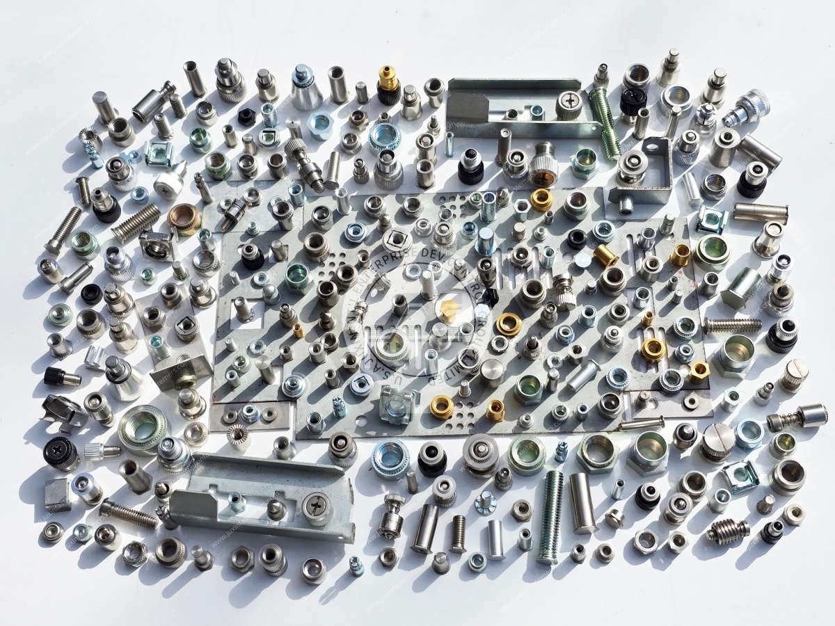
Before approving a self-clinching standoff, confirm the following.
Mounting Function
Does the application require a blind or through-threaded standoff?
PCB Clearance
Does the selected height provide sufficient mechanical and electrical clearance?
Thread Compatibility
Does the standoff match the mating screw thread system and required engagement?
Host Sheet
Are the sheet material, thickness, and hardness compatible?
Hole Preparation
Does the mounting hole match the approved dimensions and manufacturing method?
Edge Distance
Is sufficient surrounding sheet material available?
Installation Access
Can the selected press tooling reach and support the installation location?
Mechanical Performance
Are the required push-out, torque-out, and service loading conditions satisfied?
Production Quality
Can the manufacturing process maintain the required dimensional and installation consistency?
Commercial Requirements
Are the quantity, material, finish, inspection, packaging, and delivery requirements clearly defined?
A self-clinching standoff is a component installed into suitable sheet metal to provide a permanent mounting feature and controlled spacing.
Yes, where the sheet material, installation geometry, mounting height, and mechanical requirements are compatible.
A through-threaded standoff has a thread extending through its body.
A blind-threaded standoff has a defined internal thread depth that does not extend completely through the component.
The minimum thickness depends on the selected standoff design and installation requirements.
There is no universal minimum for every self-clinching standoff.
Suitable self-clinching standoffs may be installed in compatible aluminum sheet materials.
The alloy, temper, hardness, thickness, and installation requirements must be verified.
Certain specialized designs may be suitable for compatible stainless steel sheet.
Conventional designs should not automatically be considered interchangeable.
Possibly, depending on the selected standoff and the resulting hole geometry and edge condition.
The process should be validated.
Conventional self-clinching standoffs generally require controlled pressing rather than impact installation.
Push-out resistance concerns axial displacement of the installed standoff.
Torque-out resistance concerns rotation relative to the parent sheet.
It may form part of a properly designed electrical bonding path, but the complete assembly must be evaluated.
They may be suitable for compatible server chassis and electronic equipment mounting applications.
No. Different thread systems must be matched to the correct mating screw and engineering specification.
Provide the standoff drawing, thread designation, mounting height, material, finish, host sheet specifications, installation requirements, order quantity, and delivery requirements.
JUXIN FASTENERS supports international B2B sourcing inquiries for self-clinching standoffs, self-clinching nuts, self-clinching studs, and related drawing-based industrial fastening components.
Whether your project involves server chassis, AI data center equipment, telecommunications cabinets, PCB mounting assemblies, electrical enclosures, industrial automation, or precision sheet metal manufacturing, selecting the correct standoff is important to assembly reliability and production consistency.
For self-clinching standoff RFQs, please provide:
2D engineering drawing or 3D CAD model.
Through-threaded or blind-threaded configuration.
Required thread designation and pitch.
Standoff height and critical dimensions.
Body diameter and retention geometry requirements.
Host sheet material grade.
Sheet thickness and hardness requirements.
Mounting-hole diameter and tolerance.
Minimum edge-distance constraints.
Installation equipment and tooling requirements.
Required push-out or torque-out performance.
Operating temperature and corrosion conditions.
Electrical bonding or insulation requirements, where applicable.
Material and surface treatment specifications.
Inspection and quality documentation requirements.
Prototype or sample quantity.
Initial production order quantity.
Estimated annual purchasing volume.
Packaging and delivery requirements.
Target delivery schedule and destination.
For custom self-clinching standoffs, please identify any nonstandard dimensions, mounting requirements, or material specifications.
Our team can review the submitted drawings and technical requirements to confirm applicable product sourcing, manufacturing feasibility, and quotation arrangements.
Company: JUXIN FASTENERS
Website: www.juxinfasteners.com
Email: info@juxinfasteners.com
Contact JUXIN FASTENERS with your engineering drawings, technical specifications, and purchasing requirements to request a quotation for self-clinching standoffs and related OEM sheet metal fastening components.
Product Packaging
Packaging Standard
At Juxin Fasteners, we apply standardized export packaging to ensure product protection, traceability, and compliance with international logistics requirements.
1. Standard Export Packaging
Unless otherwise specified, all products will be packed according to our factory standard export packaging, which includes:
Moisture-resistant inner protection
Poly bag or small box packing as required
Reinforced export cartons
Clear labeling with part number, specification, batch number, and quantity
Palletizing for sea or air shipment when necessary
Our standard packaging is designed to ensure safe transportation, efficient warehousing, and long-distance international shipping.
2. Customized Packaging Options
We also provide customized packaging solutions according to customer requirements, including but not limited to:
Private labeling
Customized barcodes
Specific carton dimensions
Retail packaging
Special pallet configuration
Customer-specific marking and identification
So that you know, customized packaging may involve additional costs and extended lead time depending on the complexity of the requirements.
3. Compliance & Quality Assurance
All packaging processes are controlled under our ISO 9001 quality management system to ensure consistency, traceability, and product integrity throughout the supply chain.
Product Pictures
Hot Products
Contact Us
Tel.:
+86 020 8621 0320
+86 020 3121 6067
E-mail:
Technical Support:
Navigation
SEND INQUIREY