Call Us
+86 136 6007 9809
Call Us
+86 136 6007 9809

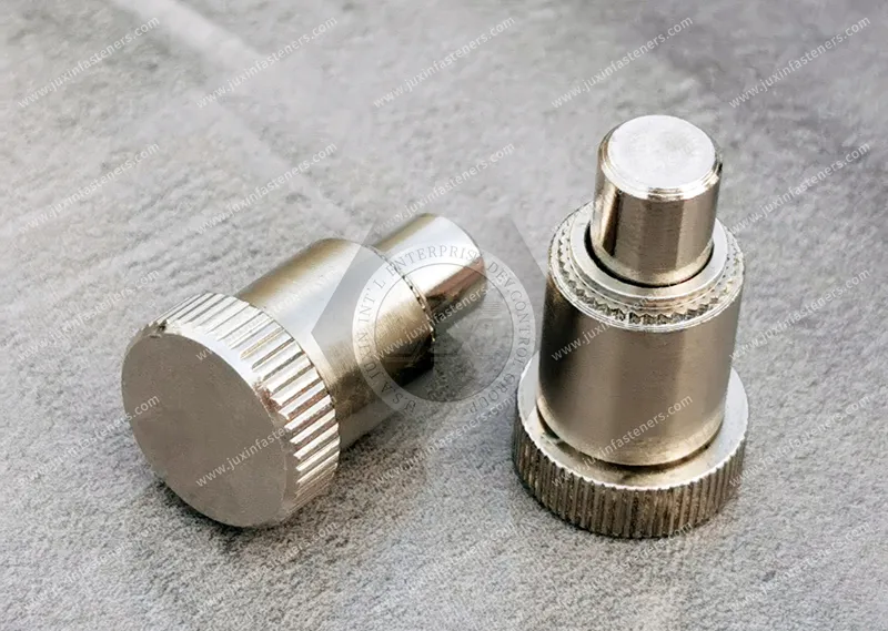
Spring-loaded locating pins are mechanical positioning components used where a rigid pin alone cannot provide the movement,
engagement, temporary retention or spring-return action required by an assembly.
Product Specification
Spring-loaded locating pins are mechanical positioning components used where a rigid pin alone cannot provide the movement,
engagement, temporary retention or spring-return action required by an assembly.
They can support functions such as:
component positioning;
alignment assistance;
temporary retention;
spring return;
controlled engagement;
workpiece positioning;
assembly guidance;
repeatable equipment setup.
They are commonly found in fixtures, industrial machinery, automation equipment and custom OEM mechanisms.
However, one of the most common sourcing mistakes is treating every spring-loaded pin as the same product.
A spring-loaded locating pin, spring plunger, indexing plunger, ball plunger, fixed locating pin and spring pin or roll pin can have very different functions.
For engineers and procurement teams, the correct starting point is therefore not:
“What size spring pin do we need?”
It is:
“What must the pin do in the assembly?”
That question determines the correct product architecture.
A spring-loaded locating pin is a positioning component in which a pin or plunger can move against an internal spring force and return when the external load is removed.
Depending on the design, it may be used to:
guide a component into position;
push a workpiece toward a fixed locator;
compensate for movement during assembly;
engage a mating feature;
provide temporary retention;
retract during component insertion;
return automatically after release.
Unlike a completely rigid locating pin, the moving element has controlled travel.
This creates additional design possibilities—but also additional engineering variables.
The complete locating system can be considered as:
Mounting Structure → Pin Body → Spring Mechanism → Moving Pin → Mating Component → Final Locating Feature
Every interface can influence performance.
This distinction is fundamental.
A spring-loaded pin may help position a component without being responsible for carrying the final operating load.
For example, a spring locating pin may push a workpiece against fixed locators during fixture loading.
In that architecture, the fixed locating elements establish the final reference while the spring-loaded device assists positioning.
The spring-loaded pin should therefore not automatically be treated as the primary structural locator.
Conversely, some retractable indexing devices intentionally engage a hole or slot to establish a defined position.
These are different mechanical functions.
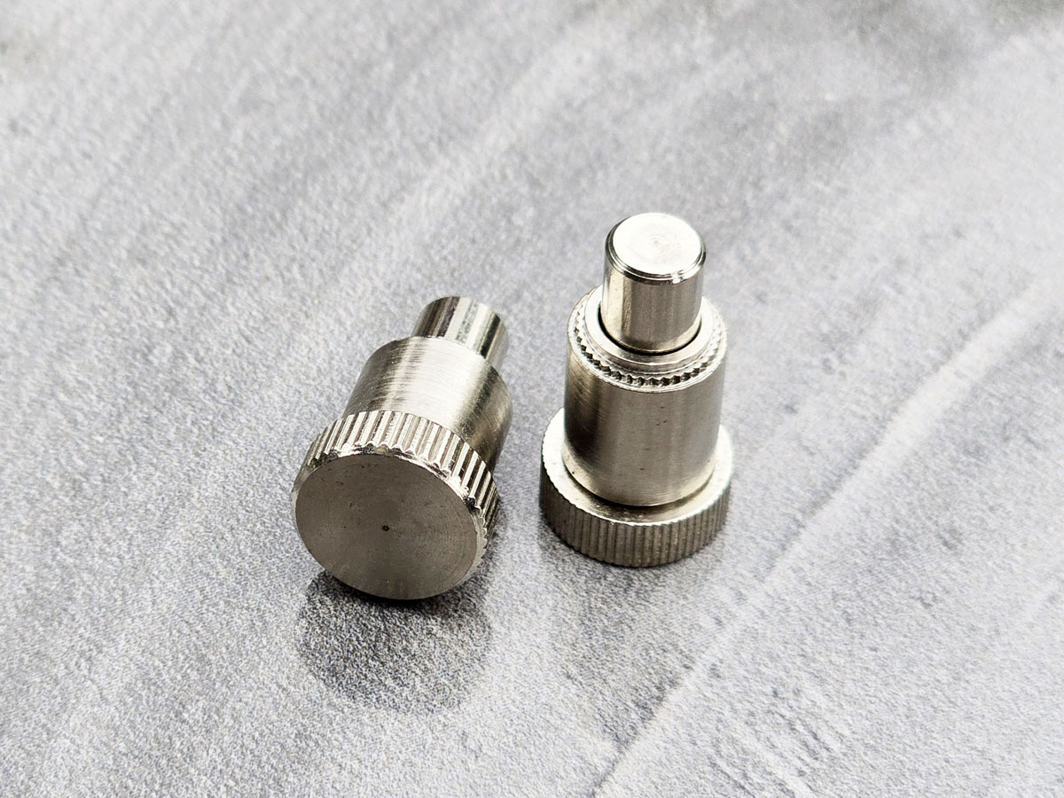
A fixed locating pin has no spring-driven axial movement.
It may be appropriate where the assembly requires:
a permanent locating feature;
direct geometric referencing;
no retraction;
no spring compensation.
A spring-loaded locating pin adds movement.
This can be useful where:
the component must move past the pin during assembly;
temporary pressure is required;
the pin must retract;
the mechanism must automatically return;
the locating sequence requires compliance.
The additional movement means engineers must also evaluate spring travel, clearance and wear.
These components are related but should not automatically be treated as interchangeable.
An indexing plunger typically uses a retractable pin to engage a corresponding hole, slot or indexing position.
The operator or mechanism can retract the pin to permit movement and allow engagement at another position.
Typical functions include:
indexing;
positive positioning;
adjustable machine settings;
fixture position changes.
A spring-loaded locating pin may instead assist positioning without acting as the final positive locking device.
Therefore:
Positioning Assistance ≠ Positive Indexing
The required function should be identified before selecting the component.
A spring plunger contains a spring-loaded nose or pin that applies force against a mating component.
It can be used for:
detent action;
positioning;
holding;
ejecting;
contact pressure.
Some spring-plunger applications overlap with locating-pin applications.
But the terms should not be treated as universally interchangeable.
Selection should be based on:
nose geometry;
required travel;
mating feature;
mounting architecture;
required function.
A ball plunger uses a spring-loaded ball rather than a projecting cylindrical locating pin.
This architecture is often useful for:
detents;
light positioning;
indexing feel;
temporary holding.
The ball can roll or move over a mating feature more easily than some pin geometries.
A cylindrical locating pin can provide a different engagement geometry.
Therefore:
Ball Contact ≠ Pin Engagement
The mating component determines which architecture is appropriate.
This distinction is especially important for search and procurement.
A spring pin, often called a roll pin, is generally a hollow or slotted/coiled pin that elastically compresses during installation into a hole.
It does not contain an internal spring-loaded moving plunger.
A spring-loaded locating pin is a mechanical assembly with a moving pin or plunger and a spring mechanism.
These are fundamentally different products.
An RFQ for “spring pins” can therefore create a completely wrong quotation if the actual requirement is a spring-loaded positioning device.
Different companies may use different names for similar custom components.
An existing drawing may call the component:
spring pin;
locating pin;
spring locator;
positioning pin;
retractable pin;
plunger;
locating plunger.
Instead of relying only on the name, engineers and suppliers should determine:
What moves?
What returns?
What does the pin contact?
Does it locate, hold, index or merely assist assembly?
Does it carry load after engagement?
These questions reveal the actual architecture.
Before selecting geometry, define the required function.
Possible functions include:
The pin helps guide one component toward the correct position.
The pin temporarily holds a component during another assembly operation.
The pin retracts under load and automatically returns after the load is removed.
The pin engages a defined position in a moving mechanism.
The pin pushes or guides a workpiece toward another locating surface.
The pin helps manage variation during component insertion or assembly.
These functions may require different designs.
A stronger spring does not automatically produce better positioning.
Spring force determines how the moving element interacts with the mating component.
Positioning accuracy can also depend on:
pin geometry;
mating-hole geometry;
clearances;
fixed locating features;
mounting accuracy;
tolerance stack-up;
wear.
Therefore:
More Spring Force ≠ More Locating Accuracy
Excessive spring force can even create unwanted assembly resistance or component loading.
The moving pin requires sufficient travel for the intended operating sequence.
Engineers should identify:
initial pin position;
compressed position;
required engagement;
required retraction;
available internal space.
Too little travel may prevent the component from clearing the pin.
Unnecessary travel may increase packaging requirements or alter the mechanism.
There is no universal correct stroke.
It must be matched to the actual assembly.
A drawing should not define only the overall component size.
For a moving spring-loaded assembly, engineers may also need to understand:
free position;
working position;
fully compressed condition;
engagement position.
This is especially important when surrounding equipment has limited clearance.
The pin does not operate alone.
It interacts with another component.
That mating feature may be:
a hole;
slot;
notch;
groove;
edge;
flat surface;
angled feature.
Its geometry affects how the pin:
enters;
retracts;
centers;
releases;
wears.
A locating-pin drawing without mating-component information can therefore be incomplete for engineering review.
The pin end can influence engagement behavior.
Depending on the application, the tip may be:
cylindrical;
rounded;
tapered;
chamfered;
custom-profiled.
There is no universal best tip.
The correct geometry depends on how the pin approaches and engages the mating feature.
A common content mistake is publishing one chamfer or taper angle as the correct solution for all locating pins.
That is not defensible.
Tip geometry should depend on:
alignment requirement;
mating-hole geometry;
insertion direction;
side movement;
release requirement;
wear considerations.
For a custom OEM component, the drawing should control the geometry.
Spring movement can accommodate certain positional changes, but it does not eliminate tolerance-stack problems.
The assembly may include tolerances from:
pin mounting position;
pin diameter;
mating hole;
panel position;
bracket position;
surrounding components.
Engineers should evaluate the complete stack rather than expecting the spring mechanism to correct every dimensional variation.
Spring travel can provide compliance.
But excessive mismatch between the pin and mating feature can still cause:
poor engagement;
side loading;
binding;
inconsistent positioning;
accelerated wear.
Therefore:
Spring Compliance ≠ Unlimited Misalignment Compensation
Side load is one of the most important considerations for moving pins.
A spring-loaded pin is typically designed to move along a defined direction.
If the mating component applies substantial lateral force while the pin is engaged, the pin may experience:
bending;
friction;
binding;
uneven wear.
The acceptable side load depends on the specific design.
JUXIN should not publish a universal side-load capacity without verified product data.
A small spring-loaded locating component should not automatically be expected to absorb the full operating load of a machine mechanism.
If the assembly requires a positive mechanical stop or structural load path, that requirement should be designed separately where necessary.
This is particularly important in:
fixtures;
automation equipment;
adjustable machinery;
moving assemblies.
Some spring-loaded locating components mount through:
sheet metal;
machined blocks;
brackets;
threaded housings;
custom mounting structures.
The mounting method affects:
available thread engagement;
body retention;
alignment;
clearance;
serviceability.
Panel thickness should therefore be considered as part of the mounting system rather than treated as a generic product parameter.
A threaded body can simplify installation into a tapped structure.
Important considerations may include:
mounting thread;
available engagement;
orientation;
installation access;
retention method;
surrounding clearance.
The thread size alone does not define the complete product.
Some applications may require another mounting architecture.
Where appropriate, custom designs can use geometry intended for:
press-in installation;
retained mounting;
bracket integration;
customer-specific assemblies.
The correct approach depends on the host component and required serviceability.
Some locating and indexing applications require the operator to manually retract the pin.
Possible actuation architectures can include:
knob;
ring;
handle;
custom actuator.
The actuation method should reflect the real operating environment.
For manually operated components, engineers should consider:
access;
gloves;
surrounding clearance;
actuation frequency;
required hand movement;
service procedure.
A mechanically functional pin can still be a poor design if operators cannot use it efficiently.
Some mechanisms require the pin to return automatically when released.
The designer should define:
required return action;
available travel;
mating geometry;
possible obstruction;
contamination environment.
Do not assume that spring return alone guarantees successful engagement.
Certain indexing architectures allow the pin to remain retracted.
This can be useful when the mating component must move freely past multiple positions.
An automatic-return design behaves differently.
This creates an important selection question:
Should the pin automatically re-engage, or remain retracted until deliberately released?
Spring-loaded locating hardware may operate repeatedly during:
production;
machine adjustment;
maintenance;
equipment servicing.
Wear can occur at:
pin tip;
mating feature;
sliding surface;
internal guide;
spring mechanism.
Required service life depends on the actual application and should not be replaced by an invented universal cycle-life number.
Surface treatment can affect more than corrosion appearance.
For a moving pin assembly, the finish may influence:
dimensions;
sliding clearance;
friction;
wear;
appearance;
corrosion behavior.
Therefore:
Finish Change ≠ Cosmetic Change Only
This becomes particularly important when an existing component is being reproduced from a drawing or sample.
If a customer requests a black spring-loaded locating pin, “black” is not a complete coating specification.
Possible finish systems may differ significantly in:
appearance;
coating build;
wear behavior;
corrosion performance;
compatibility with moving surfaces.
Where technically applicable, potential options may include:
black zinc;
black nickel;
zinc-nickel with an appropriate dark finishing system;
black oxide.
The appropriate system must be selected for the actual material and application.
For moving components, sample finishing followed by dimensional and movement evaluation can be useful before volume production.
Material and finish selection should reflect the operating environment.
Relevant factors can include:
indoor equipment;
outdoor exposure;
humidity;
condensation;
cleaning chemicals;
temperature;
mating materials.
Do not select stainless steel or a coating simply because it is perceived as universally “better.”
Both may be appropriate depending on the component design.
Selection can depend on:
required mechanical properties;
corrosion environment;
manufacturing process;
surface finish;
mating materials;
cost;
availability.
A universal strength or corrosion comparison should not be applied to every spring-loaded pin design.
Many OEM applications cannot be solved by an off-the-shelf plunger.
A custom component may require a specific combination of:
body geometry;
mounting method;
pin diameter;
pin projection;
travel;
tip shape;
spring behavior;
material;
finish;
actuation feature.
JUXIN FASTENERS supports custom fastener and hardware development based on customer 2D drawings and 3D models.
The drawing remains the primary technical control for custom production.
Some replacement and second-source projects begin with an existing physical component rather than a complete engineering drawing.
A practical sample-based development process is:
Physical Sample
→ Dimensional Review
→ Functional Review
→ Critical Feature Identification
→ Material / Finish Information Review
→ Drawing Confirmation
→ Manufacturing Feasibility
→ Prototype / Sample Development
→ Customer Validation
→ Production
A physical sample can provide important dimensional and functional information.
However, it does not automatically reveal:
exact alloy chemistry;
exact heat treatment;
exact hardness profile;
exact coating chemistry.
Where these are critical, additional customer specifications or appropriate verification may be required.
Second-source projects do not all have the same objective.
The new component must reproduce the controlled dimensions required by the existing design.
Minor differences may be considered if the component still satisfies the required form, fit and function after engineering review and validation.
A controlled dimensional or design change is intentionally evaluated.
The component is redesigned around a new application requirement.
These categories should not be mixed.
A functional equivalent may have certain differences while still being evaluated for the required application.
Engineering review should consider:
form;
fit;
function;
installation;
mating components;
critical dimensions;
material;
finish;
movement;
clearance;
environment;
serviceability.
Customer validation remains important before production substitution.
There is no universal list.
A dimension becomes critical when changing it affects the required assembly function.
Ask:
Does it affect mounting?
Does it affect pin travel?
Does it affect engagement?
Does it affect alignment?
Does it affect mating geometry?
Does it affect clearance?
Does it affect movement?
Does it affect retention?
Does it affect serviceability?
Does it affect interchangeability?
This is more useful than labeling every dimension with the same importance.
Depending on the application, these may include:
mounting interface;
pin diameter;
working projection;
travel;
mating geometry;
body clearance;
actuation geometry.
Whether each feature is actually critical depends on the assembly.
Sample validation should confirm the characteristics that matter to the actual application.
Depending on the design, this may include:
dimensions;
mounting fit;
movement;
spring return;
mating-component compatibility;
engagement;
appearance;
surface finish;
assembly clearance.
Additional customer-specific validation may be required where appropriate.
JUXIN should not represent every possible laboratory test as a standard internal capability.
Spring-loaded locating pins can be relevant to:
assembly fixtures;
adjustable mechanisms;
automation cells;
workpiece positioning;
changeover equipment.
The engineering relationship is straightforward:
Repeated positioning + controlled movement + automatic return → potential spring-loaded locating application
Relevant applications may include:
fixtures;
end-effector mechanisms;
sensor brackets;
adjustable tooling;
auxiliary positioning assemblies.
The component should be selected according to the actual locating or retention function rather than simply because the equipment contains a robot.
Potential applications include:
assembly fixtures;
welding fixtures;
inspection fixtures;
positioning equipment;
production tooling.
The spring-loaded component can support manufacturing equipment without implying that the component itself is automatically qualified as an automotive vehicle fastener.
Applications can include:
machine fixtures;
adjustable mechanisms;
guards;
tooling;
positioning assemblies;
maintenance-access mechanisms.
Repeated setup and serviceability can make retractable positioning hardware useful.

Spring-loaded locating hardware can be integrated into:
brackets;
panels;
equipment frames;
fixtures;
custom mounting structures.
Design review should include panel geometry, mounting method and available clearance.
Precision equipment can contain:
automation mechanisms;
positioning hardware;
equipment panels;
maintenance mechanisms;
custom fixtures.
A spring-loaded locating pin may be appropriate where its positioning function matches the mechanism.
This does not imply cleanroom or vacuum compatibility unless specifically designed and validated.
Possible applications include:
equipment positioning mechanisms;
adjustable assemblies;
serviceable panels;
diagnostic-equipment structures;
laboratory fixtures.
Material, finish and cleanability requirements depend on the equipment.
Use in medical equipment does not imply medical certification.
Spring-loaded locating hardware is not a generic “server fastener.”
Its relevance exists only where the equipment architecture actually requires:
alignment;
positioning;
controlled engagement;
retractable locating;
serviceable moving assemblies.
Potential equipment contexts can include:
power equipment cabinets;
cooling equipment;
liquid-cooling equipment;
cooling distribution units;
control cabinets;
rack-mounted equipment;
serviceable equipment assemblies.
Where a simple permanent threaded attachment is required, another fastener architecture may be more appropriate.
This distinction prevents forcing data-center terminology into unrelated products.
A spring-loaded locating pin may not be the correct choice when the assembly primarily requires:
permanent rigid location;
a structural load-bearing pin;
a simple roll pin;
permanent threaded attachment;
a ball detent;
positive indexing with manual release;
another dedicated locking architecture.
Choosing another component is not a compromise if it better matches the actual function.
Mechanical and design engineers may search:
spring-loaded locating pin;
retractable locating pin;
spring locating pin design;
spring-loaded positioning pin;
locating pin for fixtures;
custom spring locating pin.
Their core question is:
Which locating architecture will provide the movement and positioning behavior required by my assembly?
Procurement and supplier-development teams may search:
spring-loaded locating pin manufacturer;
custom locating pin supplier;
spring-loaded pin OEM;
custom positioning pin manufacturer;
locating pin second source;
custom fastener from drawing;
replacement spring-loaded pin.
Their core question is:
Can a supplier understand the existing component, reproduce the critical features and support sample-to-production sourcing?
Do not source a custom spring-loaded component using only a generic description such as:
“Spring pin, stainless steel, 10,000 pcs.”
That leaves the most important engineering questions unanswered.
The supplier needs to understand the actual function and controlled geometry.
For an engineering review or quotation, provide the information relevant to the project, such as:
2D drawing;
3D model;
physical sample;
product function;
application;
mounting method;
critical dimensions;
pin diameter;
required travel;
initial and compressed positions;
mating-component geometry;
panel or mounting structure;
material requirement;
surface finish;
corrosion requirement;
operating environment;
spring behavior where specified;
actuation method;
sample quantity;
production quantity;
annual usage;
packaging requirements.
Not every project requires every field.
The RFQ should focus on the characteristics that control the actual function.
JUXIN FASTENERS supports OEM and ODM fastener and custom hardware projects based on:
customer 2D drawings;
customer 3D models;
physical samples;
custom dimensions;
custom materials where applicable;
custom surface finishes where applicable.
Depending on product architecture and manufacturing feasibility, production may involve processes such as:
cold forming;
CNC machining;
turning;
stamping;
thread rolling;
secondary machining;
assembly operations.
Manufacturing-process selection depends on:
Geometry + Material + Tolerance + Thread + Component Architecture + Secondary Operations + Finish + Tooling + Quantity + Production Economics
There is no universal production-volume threshold that determines the correct process.
For applicable high-volume fastener production, automatic optical sorting can also be considered as part of production inspection planning.
For procurement teams developing an alternative source, a practical pathway is:
Existing Component
→ Drawing or Physical Sample
→ Functional Review
→ Critical Feature Identification
→ Material & Finish Review
→ Manufacturing Feasibility
→ Prototype / Sample
→ Assembly Validation
→ Production Approval
→ Volume Production
→ Long-Term Supply
This process is particularly valuable when an existing component is:
difficult to source;
discontinued;
tied to one supplier;
non-standard;
drawing-controlled;
required in increasing production volumes.
A successful spring-loaded locating-pin project should move through a clear decision path:
Required Function
→ Locating Architecture
→ Movement
→ Travel
→ Mating Geometry
→ Tolerance Stack-Up
→ Side Loading
→ Mounting Method
→ Material
→ Surface Finish
→ Operating Environment
→ Drawing / Sample
→ Sample Validation
→ Supplier Qualification
→ RFQ
For custom spring-loaded locating pins, positioning hardware, drawing-based fasteners or second-source component development, contact:
The most important sourcing question is not:
“Can you manufacture this pin?”
It is:
“Which features of this pin control the function of the complete assembly?”
Once those features are understood and controlled, engineering, procurement and the fastener supplier can evaluate the component against the same functional requirement.
Product Packaging
Packaging Standard
At Juxin Fasteners, we apply standardized export packaging to ensure product protection, traceability, and compliance with international logistics requirements.
1. Standard Export Packaging
Unless otherwise specified, all products will be packed according to our factory standard export packaging, which includes:
Moisture-resistant inner protection
Poly bag or small box packing as required
Reinforced export cartons
Clear labeling with part number, specification, batch number, and quantity
Palletizing for sea or air shipment when necessary
Our standard packaging is designed to ensure safe transportation, efficient warehousing, and long-distance international shipping.
2. Customized Packaging Options
We also provide customized packaging solutions according to customer requirements, including but not limited to:
Private labeling
Customized barcodes
Specific carton dimensions
Retail packaging
Special pallet configuration
Customer-specific marking and identification
So that you know, customized packaging may involve additional costs and extended lead time depending on the complexity of the requirements.
3. Compliance & Quality Assurance
All packaging processes are controlled under our ISO 9001 quality management system to ensure consistency, traceability, and product integrity throughout the supply chain.
Product Pictures
Contact Us
Tel.:
+86 020 8621 0320
+86 020 3121 6067
E-mail:
Technical Support:
Navigation
SEND INQUIREY