Call Us
+86 136 6007 9809
Call Us
+86 136 6007 9809

JUXIN FASTENERS supplies steel semi-tubular rivets for OEM machinery, mechanical linkages, HVAC equipment and industrial assembly.
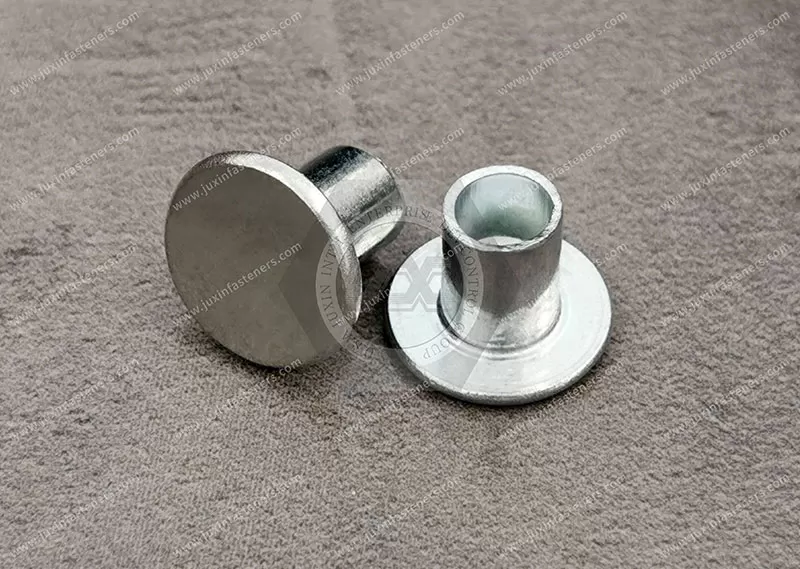
These hollow-end rivets feature a predominantly solid shank and a partially hollow tail that rolls or flares during installation.
The listed inch-size series runs from 1/8" to 1/2", subject to specification verification.
Explore material selection, corrosion protection, joint design, automated riveting, dimensional inspection and custom drawing-based manufacturing requirements.
Product Specification
Steel Semi-Tubular Rivets for OEM Manufacturing and Industrial Assembly
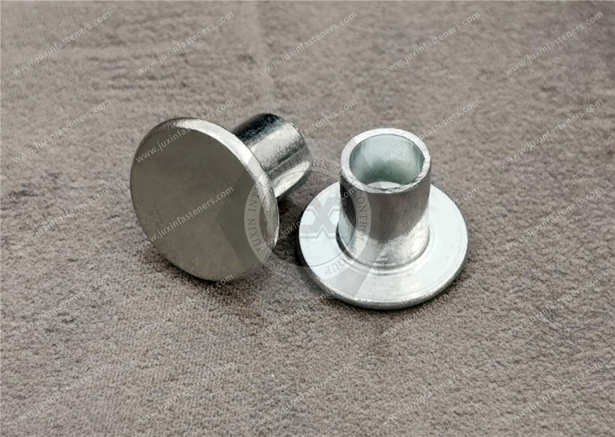
Steel semi-tubular rivets are permanent mechanical fasteners featuring a predominantly solid cylindrical shank and a partially hollow tail.
During installation, the hollow end is rolled or flared outward to form a retaining head, securing the assembled components.
Also referred to as steel hollow-end rivets, these fasteners are widely recognized in the American industrial riveting market.
Their partially hollow tail generally requires less forming force than a comparable solid rivet, making them relevant to repetitive OEM assembly and selected mechanical pivot applications.
JUXIN FASTENERS supplies steel semi-tubular rivets for industrial manufacturing projects requiring suitable joint strength, controlled dimensions, repeatable installation and compatibility with production tooling.
Custom requirements can be evaluated according to customer engineering drawings, material specifications and annual production demand.
Product Specifications and Available Size Designations
Product Name: Steel Semi-Tubular Rivets
Alternative Name: Steel Hollow-End Rivets
Product Category: Hollow Rivets
Primary Material: Steel
Product Construction: Predominantly Solid Shank with Partially Hollow Tail
Installation Principle: Mechanical Tail Rolling or Flaring
Listed Nominal Diameter Series:
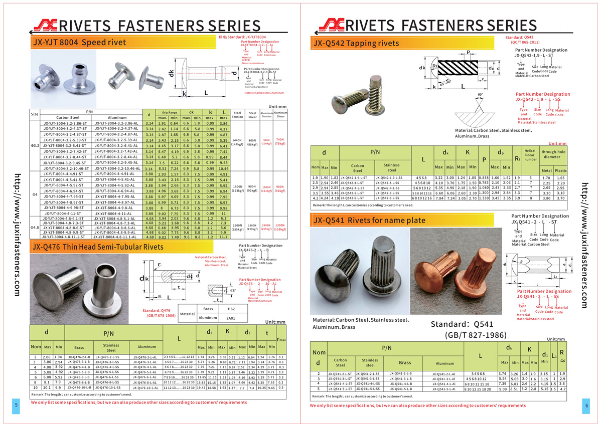
1/8" — 3.175 mm reference
9/64" — 3.5719 mm reference
5/32" — 3.9688 mm reference
3/16" — 4.7625 mm reference
1/4" — 6.35 mm reference
5/16" — 7.9375 mm reference
3/8" — 9.525 mm reference
7/16" — 11.1125 mm reference
1/2" — 12.7 mm reference
The listed inch sizes are taken from the existing product information.
Exact availability, dimensional tolerances, lengths and head-style combinations must be verified against the applicable specification drawings.
Metric conversions are provided for dimensional reference only.
They do not establish separately available metric product sizes or interchangeability.
The original product-family information also identifies oval and truss head styles. Their availability for specific steel rivet sizes requires confirmation.
The steel grade, mechanical properties, surface treatment and finished dimensions should be specified or verified for each OEM project.
What Is a Steel Semi-Tubular Rivet?
A semi-tubular rivet is a mechanical fastener with a manufactured head at one end and a shallow cavity at the opposite end.
The cavity creates a tubular tail section that can be deformed outward during installation.
The main structural features include:
Manufactured head.
Solid shank section.
Partially hollow tail.
Tail cavity diameter.
Tail cavity depth.
Tubular wall thickness.
During installation, the rivet passes through prepared holes in the assembled materials. A suitable setting tool then forms the hollow tail into a retaining head.
The completed joint is held between the manufactured head and the newly formed shop head.
Depending on the assembly design, the connection may provide rigid retention or allow controlled rotational movement.
The fastener's suitability depends on the specified steel material, dimensions, installation process and service loads.
Steel Semi-Tubular Rivets vs. Other Rivet Types
Semi-Tubular Rivets
Semi-tubular rivets have a partially hollow tail that is designed for mechanical end forming.
They are commonly selected for repetitive industrial assembly and certain pivoting joints.
Solid Rivets
Solid rivets have no hollow tail. Installation requires deformation of a solid shank end.
For comparable geometry and material, solid rivets generally require greater forming force.
Fully Tubular Rivets
Fully tubular rivets have a continuous hollow passage through the body.
Their structure and forming characteristics differ from those of semi-tubular rivets.
Blind Rivets
Conventional blind rivets are designed for installation when access is available from only one side.
Semi-tubular rivets generally require access to both sides for proper head support and tail forming.
These rivet types should not be substituted without evaluating the complete joint design.
Steel Material Selection for Semi-Tubular Rivets
Steel offers a range of mechanical properties that can be useful for permanent industrial fastening.
However, steel is not a single material grade.
Material selection should consider:
Steel composition.
Mechanical strength.
Hardness.
Ductility.
Cold-forming behavior.
Surface condition.
Corrosion exposure.
Compatibility with adjoining components.
Carbon Steel Rivets
Carbon steel is commonly used in industrial semi-tubular riveting.
The exact grade and material condition influence the rivet's ability to form a suitable retaining head without cracking or excessive deformation.
The material must also provide the mechanical characteristics required by the completed joint.
The available JUXIN product information confirms steel but does not identify a specific carbon steel grade. The final material specification must therefore be verified.
Steel Hardness and Formability
A steel rivet must be compatible with the intended setting process.
Excessive hardness can increase forming force and the risk of cracking.
Insufficient mechanical strength may make the rivet unsuitable for the required joint loads.
Material hardness, ductility and finished joint performance should be evaluated together.
Surface Finishes and Corrosion Protection
Steel rivets may require surface protection depending on the operating environment.
Common industry options include:
Plain steel.
Zinc-plated steel.
Other customer-specified protective finishes.
These are industry finish options for engineering evaluation, not confirmation that every treatment is currently available for every JUXIN part number.
Plain Steel
Plain steel may be suitable for selected protected environments or assemblies where a subsequent finishing process is planned.
Its corrosion behavior must be considered in the complete product design.
Zinc-Plated Steel
Zinc plating can improve corrosion protection under appropriate service conditions.
However, coating thickness, plating process, passivation and corrosion performance must be specified where relevant.
Surface treatments may also influence dimensional fit, friction and riveting behavior.
Galvanic Corrosion Considerations
Where steel rivets contact aluminum, stainless steel or other dissimilar metals, galvanic corrosion should be evaluated according to the environment and joint design.
The appropriate coating or isolation method should be established from the actual service conditions.
Oval Head and Truss Head Semi-Tubular Rivets
The original product-family information identifies oval and truss head configurations.
Oval Head
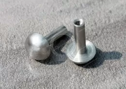
Oval head semi-tubular rivets provide a rounded manufactured head profile.
Selection considerations include head height, bearing area, appearance and assembly clearance.
Truss Head
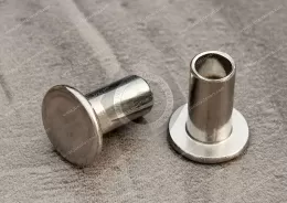
Truss head semi-tubular rivets generally provide a broader, lower-profile head geometry.
They may be considered where bearing area and head projection are important.
Actual head dimensions must be confirmed from the approved drawing.
Other head styles are recognized in the industry, but their availability should not be assumed for this JUXIN product.
Critical Engineering Dimensions for Steel Semi-Tubular Rivets
Selecting a steel semi-tubular rivet requires more than matching the nominal diameter.
1. Shank Diameter
Shank diameter influences hole fit, joint alignment and mechanical performance.
The actual diameter and tolerance must match the installation requirements.
2. Rivet Length
Rivet length must accommodate the assembled material thickness and provide enough tail material for the specified retaining head.
The required length depends on grip thickness and the applicable clinch allowance.
3. Hollow-End Diameter
The cavity diameter influences the thickness of the tubular tail and its response to forming.
It must be compatible with the setting tool.
4. Hollow-End Depth
The depth of the tail cavity affects the volume of material available for deformation and the resulting shop-head geometry.
5. Tail Wall Thickness
Wall thickness affects setting force, deformation behavior and the risk of cracking or splitting.
6. Head Diameter
The manufactured head provides a bearing surface against the assembled material.
The correct head diameter should be selected based on joint geometry and substrate characteristics.
7. Head Height
Head height influences clearance, seating and compatibility with adjacent parts.
8. Installation Hole Diameter
The hole must allow appropriate insertion and alignment without excessive clearance.
Incorrect hole size can contribute to loose joints, workpiece damage or inconsistent forming.
9. Grip Thickness
The total thickness of the assembled components must be considered when selecting rivet length and setting parameters.
10. Dimensional Tolerances
For automated production, critical dimensions may include shank diameter, overall length, head geometry, hollow-end dimensions, concentricity and burr condition.
All dimensions and tolerances should be controlled according to the approved OEM drawing.
Clinch Allowance and Rivet Length Selection
Clinch allowance is the additional rivet length required beyond the assembled material thickness to form the retaining shop head.
For a specific rivet design, the required rivet length is determined by the material stack-up and the approved clinch allowance.
A general engineering relationship is:
Required Rivet Length = Total Workpiece Thickness + Specified Clinch Allowance
The actual allowance depends on the rivet diameter, hollow-end geometry, material and setting process.
Do not use a universal allowance without consulting the relevant drawing or validated tooling specification.
For moving joints, the desired axial clearance and freedom of movement must also be considered.
Industrial Applications and Engineering Solutions
Steel semi-tubular rivets may be evaluated for a range of end-user manufacturing applications.
The following examples describe relevant engineering scenarios. Final suitability depends on the approved rivet design, joint requirements and validation results.
1. Industrial Machinery, Hinges and Mechanical Linkages
Industrial machinery manufacturers may require permanent fastening points that permit controlled rotation or articulation.
Potential applications include:
Mechanical linkages.
Pivoting brackets.
Hinge components.
Moving equipment assemblies.
Small articulated mechanisms.
Engineering Challenge
The joint must retain the components while providing the intended movement.
Excessive clamping may restrict rotation, while insufficient retention may result in looseness, wear or misalignment.
Engineering Solution
A steel semi-tubular rivet can be evaluated for selected pivoting joints because the tail is formed locally while much of the shank remains solid.
Important considerations include:
Shank diameter.
Hole clearance.
Axial joint clearance.
Component stack-up.
Bearing wear.
Cyclic loading.
Lubrication where applicable.
Corrosion exposure.
Formed head geometry.
Where a controlled bearing surface or precise pivot length is required, a shoulder rivet or another specialized component may be more appropriate.
2. HVAC and Home Appliance Manufacturing
HVAC and appliance manufacturers frequently assemble fabricated metal components in repetitive production operations.
Potential applications include:
Equipment brackets.
Mechanical control linkages.
Sheet-metal subassemblies.
Internal support hardware.
Selected moving components.
Engineering Challenge
The fastening process must provide consistent retention without excessive installation force, workpiece distortion or rework.
Engineering Solution
Steel semi-tubular rivets may offer a suitable mechanically formed connection when the rivet geometry, material and installation equipment are compatible.
Production engineers should evaluate:
Material thickness.
Installation hole size.
Head bearing area.
Rivet length.
Tail-forming requirements.
Tooling alignment.
Surface coating.
Inspection criteria.
For HVAC applications exposed to moisture, the specified corrosion-protection system must be appropriate for the service environment.
3. Electrical Equipment and Lighting Fixture Manufacturing
Electrical equipment and lighting manufacturers may use permanent riveted joints in selected mechanical assemblies.
Potential applications include:
Lighting brackets.
Electrical enclosure hardware.
Equipment support components.
Mechanical retaining parts.
Thin-metal mounting assemblies.
Engineering Challenge
Thin components may require controlled forming forces to avoid distortion and maintain dimensional stability.
Engineering Solution
A semi-tubular steel rivet can be considered where a permanent non-threaded joint is required and both sides are accessible.
Engineering requirements may include:
Panel thickness.
Hole positioning.
Tool clearance.
Head geometry.
Installation force.
Corrosion protection.
Electrical clearance.
Assembly inspection.
Steel rivets are electrically conductive and should not be assumed to provide electrical insulation.
Electrical bonding or grounding functions require separate engineering verification.
4. Automotive Component Manufacturing
Automotive OEM and Tier-1/Tier-2 manufacturers may evaluate steel semi-tubular rivets for selected mechanical subassemblies.
Potential applications include:
Non-safety-critical linkages.
Interior mechanical hardware.
Bracket assemblies.
Pivoting components.
Repetitive sheet-metal joints.
Engineering Challenge
Automotive components may experience vibration, repeated movement, temperature variation and corrosion exposure.
Engineering Solution
The rivet and installed joint should be evaluated against the required mechanical and environmental conditions.
Important factors include:
Material grade.
Joint loading.
Fatigue performance.
Hole wear.
Axial clearance.
Installation repeatability.
Surface finish.
Corrosion exposure.
Customer-defined quality requirements.
Use in safety-critical or structural automotive systems requires application-specific validation and customer approval.
General industry applications do not establish qualification for a particular vehicle component.
Steel Semi-Tubular Rivet Installation Methods
Semi-tubular rivets are typically installed by mechanically forming the hollow tail.
Depending on the assembly, suitable equipment may include:
Riveting presses.
Rivet squeezers.
Orbital riveting machines.
Radial riveting machines.
Other compatible mechanical setting systems.
Equipment selection depends on the rivet design, material and production requirements.
Step 1: Verify the Rivet
Confirm the material, shank diameter, length, head geometry and hollow-end dimensions.
Step 2: Prepare the Workpieces
Check the hole dimensions, material thickness, surface condition and component alignment.
Remove unacceptable burrs or defects.
Step 3: Position the Rivet
Insert the rivet through the prepared holes and seat the manufactured head correctly.
Step 4: Support the Assembly
Use suitable fixtures and tooling to prevent unwanted movement or deformation.
Step 5: Form the Hollow Tail
Apply the validated setting process to roll or flare the hollow tail outward.
The forming process must produce the required retaining head without unacceptable cracking, splitting or workpiece distortion.
Step 6: Inspect the Completed Joint
Verify head formation, component seating and any required mechanical function.
For pivot joints, confirm the specified rotational movement and axial clearance.
The correct installation force, stroke, tool geometry and cycle parameters must be established for the actual product.
Semi-Tubular Rivets for Automated OEM Assembly
Steel semi-tubular rivets may be suitable for repetitive manufacturing operations using compatible riveting and feeding equipment.
Potential benefits include:
Lower tail-forming force than comparable solid rivets.
Reduced installation effort.
Repeatable forming operations.
Compatibility with selected automated feeding systems.
Suitability for certain rigid or pivoting joints.
These benefits depend on the material, geometry and validated production process.
Production Engineering Considerations
For production managers, important factors include:
Rivet feeding and orientation.
Installation tooling.
Fixture design.
Hole alignment.
Setting force and stroke.
Cycle time.
Tool wear.
Workpiece deformation.
Finished joint consistency.
Inspection and rework.
The objective is a repeatable assembly process that meets engineering requirements throughout the intended production program.
Common Installation Problems and Prevention
Problem: Cracked or Split Hollow Tail
Possible causes:
Excessive forming deformation.
Inappropriate steel hardness.
Incorrect tool geometry.
Inconsistent tail wall thickness.
Recommended evaluation:
Review material condition, cavity geometry and forming parameters.
Problem: Incomplete Tail Rolling
Possible causes:
Insufficient setting force.
Incorrect tool stroke.
Unsuitable rivet length.
Incompatible tooling.
Recommended evaluation:
Verify the specified rivet geometry and installation process.
Problem: Loose Joint
Possible causes:
Excessive hole clearance.
Incorrect rivet length.
Incomplete head formation.
Variation in assembled material thickness.
Recommended evaluation:
Check hole fit, grip thickness and finished joint geometry.
Problem: Pivot Joint Binding
Possible causes:
Excessive axial compression.
Incorrect component stack-up.
Poor hole alignment.
Inadequate designed clearance.
Recommended evaluation:
Review the pivot geometry and forming process.
Problem: Workpiece Distortion
Possible causes:
Excessive installation force.
Inadequate backing support.
Incorrect tool alignment.
Thin or soft workpiece materials.
Recommended evaluation:
Review fixture support and the required forming force.
Problem: Corrosion at the Joint
Possible causes:
Inadequate surface protection.
Coating damage during installation.
Exposure to moisture or chemicals.
Contact with dissimilar metals.
Recommended evaluation:
Review the finish specification and complete environmental exposure conditions.
Quality Inspection for OEM Steel Semi-Tubular Rivets
Quality requirements should follow the approved engineering drawing and customer-defined acceptance criteria.
Dimensional Inspection
Relevant characteristics may include:
Shank diameter.
Rivet length.
Head diameter.
Head height.
Hollow-end diameter.
Hollow-end depth.
Tail wall thickness.
Concentricity.
Critical tolerances.
Material Verification
Confirm the specified steel grade, hardness and material condition where required.
Surface Finish Inspection
Where a coating is specified, inspect relevant coating characteristics according to the approved requirements.
Visual Inspection
Check for:
Cracks.
Splits.
Burrs.
Surface damage.
Head deformation.
Irregular hollow-end geometry.
Installation Validation
Verify compatibility with the intended tooling and assembled materials.
Functional Testing
Depending on the application, customer-defined testing may include:
Mechanical retention.
Shear resistance.
Tensile or pull-out resistance.
Pivot movement.
Cyclic loading.
Vibration performance.
Corrosion performance.
These are potential validation requirements, not claims that every test is performed on every JUXIN rivet.
Inspection methods, sampling plans and documentation should be established for the specific OEM program.
Custom Steel Semi-Tubular Rivets to Engineering Drawings
Standard catalog sizes may not meet every industrial assembly requirement.
Custom engineering review may consider:
Shank diameter.
Overall rivet length.
Manufactured head style.
Head diameter and height.
Hollow-end diameter and depth.
Tail wall thickness.
Steel grade and hardness.
Surface finish.
Dimensional tolerances.
Installation hole dimensions.
Assembly material and thickness.
Required mechanical performance.
Expected production quantity.
A complete 2D engineering drawing or 3D CAD file provides the preferred basis for technical review.
For moving joints, the drawing should also specify the required pivot clearance, motion and operating loads.
Frequently Asked Engineering Questions
What are steel semi-tubular rivets?
They are permanent mechanical fasteners with a predominantly solid shank and a partially hollow tail that is rolled or flared during installation.
Are semi-tubular rivets the same as hollow-end rivets?
Hollow-end rivets is a commonly used American industry term for semi-tubular rivets.
Are semi-tubular rivets hollow throughout the entire body?
No. The hollow section is located at the tail, unlike a fully tubular rivet with a continuous opening.
Do steel semi-tubular rivets require access to both sides?
Generally, yes. The manufactured head must be supported while the hollow tail is formed.
Why do semi-tubular rivets require less setting force than solid rivets?
Only the partially hollow tail needs to be rolled or flared, reducing the amount of material that must be displaced.
Actual force depends on material, dimensions and installation conditions.
Can steel semi-tubular rivets be used for pivot joints?
Yes, selected designs can provide permanent retention while allowing controlled movement. Joint clearance, loading and wear must be evaluated.
What nominal diameters are listed for this product?
The existing specifications list 1/8", 9/64", 5/32", 3/16", 1/4", 5/16", 3/8", 7/16" and 1/2".
Actual available combinations and tolerances must be verified against the specification sheet.
Are these rivets made from low-carbon steel?
Low-carbon steel is common in the industry, but the exact JUXIN steel grade has not been confirmed in the available product information.
Can steel semi-tubular rivets be zinc plated?
Zinc plating is a common industrial option for steel rivets. Its availability and coating requirements for a specific JUXIN product must be confirmed.
Are steel semi-tubular rivets suitable for automotive components?
They may be suitable for selected components when joint performance, material requirements and customer qualification are satisfied.
Can steel semi-tubular rivets be installed automatically?
Many semi-tubular rivet designs are compatible with automated riveting systems. Actual feeding and tooling compatibility must be verified.
Can custom dimensions be manufactured?
Custom dimensions can be evaluated according to customer drawings, material specifications and manufacturing requirements.
What information is needed for an OEM quotation?
A dimensioned drawing, steel grade, head style, hollow-end geometry, finish, installation requirements and estimated production quantity provide a useful basis for technical evaluation.
Request a Drawing-Based OEM RFQ
JUXIN FASTENERS supports engineering inquiries for steel semi-tubular rivets and custom hollow-end fastening components used in industrial manufacturing.
For a new OEM project or an existing production component, please provide:
2D engineering drawing or 3D CAD file.
Required steel grade and material condition.
Nominal shank diameter.
Rivet length.
Head style and dimensions.
Hollow-end diameter and depth.
Critical dimensional tolerances.
Required surface finish.
Assembly materials and thickness.
Installation equipment and process requirements.
Mechanical performance specifications.
Quality and inspection requirements.
Prototype or initial production quantity.
Estimated annual production demand.
Target project schedule.
Our team can review the supplied technical requirements and discuss the appropriate next steps for engineering clarification and quotation.
JUXIN FASTENERS
Website: https://www.juxinfasteners.com/
Email: info@juxinfasteners.com
Submit Your Engineering Drawings for a Custom Steel Semi-Tubular Rivet RFQ.
Product Packaging
Packaging Standard
At Juxin Fasteners, we apply standardized export packaging to ensure product protection, traceability, and compliance with international logistics requirements.
1. Standard Export Packaging
Unless otherwise specified, all products will be packed according to our factory standard export packaging, which includes:
Moisture-resistant inner protection
Poly bag or small box packing as required
Reinforced export cartons
Clear labeling with part number, specification, batch number, and quantity
Palletizing for sea or air shipment when necessary
Our standard packaging is designed to ensure safe transportation, efficient warehousing, and long-distance international shipping.
2. Customized Packaging Options
We also provide customized packaging solutions according to customer requirements, including but not limited to:
Private labeling
Customized barcodes
Specific carton dimensions
Retail packaging
Special pallet configuration
Customer-specific marking and identification
So that you know, customized packaging may involve additional costs and extended lead time depending on the complexity of the requirements.
3. Compliance & Quality Assurance
All packaging processes are controlled under our ISO 9001 quality management system to ensure consistency, traceability, and product integrity throughout the supply chain.
Product Pictures
Contact Us
Tel.:
+86 020 8621 0320
+86 020 3121 6067
E-mail:
Technical Support:
Navigation
SEND INQUIREY