Call Us
+86 136 6007 9809
Call Us
+86 136 6007 9809

120° Countersunk Stainless Steel Blind Rivets
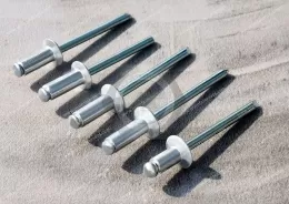
JUXIN FASTENERS supplies open-end blind rivets with stainless steel bodies, steel pull mandrels and 120° countersunk heads.
Designed for one-sided installation, these fasteners provide reduced head projection when seated in correctly prepared countersunk holes.
Suitable for compatible sheet-metal panels, equipment enclosures and OEM assemblies requiring controlled surface clearance.
Material grades, grip range and corrosion requirements must be verified against the selected specification.
Product Specification
120° Countersunk Stainless Steel Open-End Blind Rivets
Product Overview
JUXIN FASTENERS supplies 120° countersunk stainless steel open-end blind rivets for industrial sheet-metal fastening and OEM equipment assembly.
The product features a stainless steel rivet body, steel pull mandrel and 120° countersunk head. Its open-end break-mandrel construction allows permanent mechanical fastening from one accessible side of the joint.
The countersunk head is designed to fit a matching 120° recess, reducing head projection above the panel surface when the mounting-hole geometry and installation conditions are correct.
This configuration is particularly relevant to engineering applications requiring controlled surface clearance, limited rear-side installation access and a specified stainless steel rivet body.
Product Identification and Material Configuration
| Item | Specification |
|---|---|
| Product Name | 120° Countersunk Stainless Steel Blind Rivets |
| Part Number Series | JX-SSK-X-BS |
| Rivet Construction | Open-End Break-Mandrel |
| Head Style | 120° Countersunk Head |
| Rivet Body | Stainless Steel |
| Pull Mandrel | Steel |
| Stainless Steel Description | 18-8, as stated in original product information |
| Exact Stainless Steel Grade | To be confirmed |
| Mandrel Grade and Finish | To be confirmed |
| Installation | One-Sided Blind Riveting |
| Technical Reference | Original PDF/CAD, pages 99–100 |
Important Material Clarification
This product uses a stainless steel body and a steel mandrel.
It is not an all-stainless-steel blind rivet.
The original material description refers to 18-8 stainless steel, but the exact alloy grade and applicable material standard require confirmation.
Corrosion performance must be evaluated for both the rivet body and the mandrel configuration.
Key Product Features
Stainless steel rivet body
Steel pull mandrel
120° countersunk head
Open-end blind rivet construction
One-sided installation
Reduced head projection in a correctly prepared countersink
Permanent mechanical fastening
Suitable for compatible sheet-metal assemblies
OEM dimensional requirements subject to technical review
Dimensions and Technical Specifications
| Parameter | Requirement |
|---|---|
| Rivet Body Diameter (d) | Refer to original PDF/CAD |
| Rivet Body Length (L) | Refer to original PDF/CAD |
| Countersunk Head Diameter (D) | Refer to original PDF/CAD |
| Countersunk Head Height | Refer to original PDF/CAD |
| Countersunk Head Angle | 120° |
| Mandrel Diameter | According to selected product |
| Recommended Hole Diameter | According to product specification |
| Minimum Grip Thickness | According to product specification |
| Maximum Grip Thickness | According to product specification |
| Shear Strength | According to verified technical data |
| Tensile Strength | According to verified technical data |
| Material and Surface Finish | According to approved drawing |
Technical Documentation
Refer to the existing JUXIN PDF/CAD specification, pages 99–100.
The original engineering drawings and dimensional tables govern actual available sizes, tolerances, material requirements and mechanical characteristics.
Engineering Solution 1 — Flush-Mount Fastening and Surface Clearance
The main engineering advantage of a countersunk blind rivet is its ability to reduce fastener head projection.
In a correctly designed assembly, the 120° head seats within a matching countersunk hole instead of protruding like a conventional dome head.
This may be important for:
Equipment covers positioned close to adjacent components
Sliding or overlapping sheet-metal panels
Cabinet assemblies with limited external clearance
Metal enclosures requiring a relatively smooth exposed surface
OEM products with specified head projection limits
However, a countersunk blind rivet is not automatically flush in every application.
The final head position depends on the actual rivet head geometry, countersink dimensions, panel thickness and installation conditions.
Engineering Solution 2 — Countersink Geometry and Dimensional Compatibility
The 120° countersink angle is a defining characteristic of this product.
A mating countersink must be designed to accommodate the rivet's actual head geometry.
Critical parameters include:
Countersink included angle
Countersink major diameter
Countersink depth
Rivet head diameter
Rivet head height
Mounting-hole diameter
Panel thickness
Installed head projection
A countersink designed for a different head angle should not be assumed compatible.
Incorrect countersink geometry can produce uneven head contact, excessive projection or insufficient panel support.
For OEM assemblies, the countersink requirements should be specified in the engineering drawing.
Engineering Solution 3 — Thin Sheet-Metal Design and Remaining Panel Thickness
Countersinking removes or displaces material around the mounting hole.
This is especially important in thin sheet-metal assemblies.
A deep countersink may reduce the material available to support the rivet head.
Before approving a countersunk rivet, engineers should evaluate:
Original sheet thickness
Countersink depth
Remaining material beneath the head
Local bearing stress
Panel stiffness
Joint loading
Rivet spacing and edge distance
For very thin panels, a conventional dome head or large flange blind rivet may be more appropriate.
The correct head style should be selected according to the complete joint design rather than appearance alone.
Engineering Solution 4 — Grip Range and Material Stack-Up
Grip range describes the combined thickness of the materials that a selected blind rivet is designed to fasten.
The total assembly thickness must fall within the specified minimum and maximum grip range.
Rivet body length and grip range are different parameters.
The engineer should verify:
Minimum material stack-up
Maximum material stack-up
Rivet body diameter
Rivet body length
Hole diameter
Countersink geometry
Blind-side clearance
Required joint performance
This product is identified as a standard open-end countersunk blind rivet.
It should not be classified as a multi-grip rivet unless confirmed by the original technical documentation.
Engineering Solution 5 — Stainless Steel Body and Steel Mandrel Selection
The stainless steel body may provide corrosion resistance appropriate to its grade and environment.
The steel mandrel performs the setting function and must be evaluated separately.
The mixed-metal construction is relevant to purchasing and engineering decisions because a stainless steel body does not make the entire fastener assembly stainless steel.
Important considerations include:
Stainless steel body grade
Steel mandrel grade and finish
Mandrel break behavior
Retained mandrel condition
Mechanical performance
Corrosion exposure
Mating material compatibility
For wet, outdoor, coastal or chemically exposed environments, the required corrosion performance should be specified rather than inferred from the term stainless steel.
Engineering Solution 6 — Installation and Production Process Control
A compatible blind riveting tool and nosepiece are required.
Typical installation procedure:
Prepare the mounting hole and 120° countersink according to the approved drawing.
Confirm the material stack-up falls within the selected grip range.
Align the components.
Insert the rivet through the prepared holes.
Seat the countersunk head in the matching recess.
Engage the steel mandrel using the appropriate riveting tool.
Pull the mandrel to form the blind-side retaining portion.
Complete the setting operation at the designed mandrel break point.
Inspect head seating, installed projection and blind-side formation.
Production engineers should control the installation process using the actual rivet configuration, tooling and assembly materials.
Engineering Solution 7 — Vibration, Fatigue and Joint Reliability
Blind riveting provides permanent mechanical fastening, but joint performance under vibration depends on the complete assembly.
The original description should not be interpreted as a guarantee that the rivet cannot loosen or fail under any vibration condition.
Relevant engineering factors include:
Rivet diameter and material
Grip range
Mounting-hole fit
Countersink geometry
Panel stiffness
Joint loading
Vibration and fatigue exposure
Edge distance and spacing
Installation quality
Shear strength and tensile strength are separate mechanical characteristics.
A flush-mounted head does not automatically establish adequate shear, tensile or fatigue performance.
For demanding OEM applications, the installed joint should be validated under representative operating conditions.
Metric and Inch Diameter Reference
Common nominal blind rivet diameter references include:
| Metric Diameter | Approximate Inch Reference |
|---|---|
| 2.4 mm | 3/32 in |
| 3.2 mm | 1/8 in |
| 4.0 mm | 5/32 in |
| 4.8 mm | 3/16 in |
| 6.4 mm | 1/4 in |
These values are general nominal references, not a confirmed list of available sizes for this JUXIN product.
Actual metric and inch-designated rivets must be checked for dimensional compatibility, hole requirements, head geometry and grip range before substitution.
Industrial Applications & Engineering Fastening Solutions
The following industrial applications describe potential engineering uses for 120° countersunk stainless steel body blind rivets with steel mandrels.
Suitability depends on the approved drawing, material specification, operating environment and required joint performance. These examples do not imply industry-specific certification.
1. Container Manufacturing — Flush-Mount Equipment Panels
Container manufacturing may involve auxiliary metal panels, internal fittings, protective covers and equipment compartments.
A countersunk blind rivet may be considered where one-sided installation is required and protruding fastener heads could interfere with adjacent parts.
Engineering checks include countersink depth, panel thickness, vibration and environmental corrosion.
Structural container connections require separate qualification.
2. AI Data Center Cabinet Manufacturing — Server Cabinets and Metal Enclosures
AI data center equipment uses server cabinets, rack enclosures, power distribution housings and cooling equipment panels.
120° countersunk blind rivets may be considered for compatible auxiliary covers and sheet-metal panels where controlled head projection is beneficial.
Designers should verify:
Head clearance
Countersink compatibility
Panel thickness
Installation access
Electrical bonding requirements
Maintenance access
Contamination and loose-particle controls
Open-end blind rivets are not inherently sealed or electrically conductive joints.
3. Electrical Power Equipment Manufacturing — Control and Distribution Cabinets
Electrical power equipment includes switchgear housings, control cabinets and power distribution enclosures.
Countersunk blind rivets may be considered for approved mechanical panels requiring a relatively smooth surface.
The fastening design must not compromise electrical clearance, grounding, bonding or equipment safety requirements.
4. Telecommunications Equipment Manufacturing — Equipment Housings
Telecommunications equipment uses metal enclosures, protective panels and auxiliary brackets.
A 120° countersunk head may help reduce protrusions where components are closely spaced.
Outdoor installations require separate evaluation of the stainless steel body, steel mandrel finish and environmental exposure.
5. Semiconductor Equipment Manufacturing — Precision Equipment Covers
Semiconductor equipment may use precision sheet-metal covers, cabinet panels and auxiliary housings.
Countersunk blind rivets may be evaluated where reduced head projection is useful and permanent fastening is acceptable.
Engineers should consider:
Particle generation
Installation debris
Surface cleanliness
Material compatibility
Maintenance access
Dimensional consistency
Cleanroom or process-chamber suitability must not be assumed without qualification.
6. Medical Equipment Manufacturing — Instrument Enclosures
Medical equipment may include instrument cabinets, equipment housings and non-patient-contact support panels.
Countersunk rivets may be considered where head clearance or a relatively smooth exposed surface is required.
Cleaning, corrosion, material traceability and application-specific regulatory requirements must be reviewed.
No medical-device certification, biocompatibility or sterilization suitability is implied.
7. Food Processing Machinery Manufacturing — Non-Product-Contact Covers
Food-processing equipment uses guards, protective panels and machinery enclosures.
Countersunk blind rivets may be considered for appropriate non-product-contact assemblies.
However, countersunk recesses and open-end construction require careful evaluation for cleanability, moisture retention and crevice formation.
The steel mandrel must also be evaluated for corrosion.
These rivets are not automatically suitable for hygienic or direct food-contact applications.
8. Automotive Manufacturing — Auxiliary Body and Equipment Panels
Automotive OEM and Tier-1 manufacturing may use flush-mounted fasteners for compatible sheet-metal accessories, covers and auxiliary assemblies.
Engineering considerations include:
Surface clearance
Vibration and fatigue
Countersink geometry
Corrosion
Installation consistency
Customer-specific quality requirements
Crash-critical and other safety-critical applications require separate validation.
9. Motorcycle Manufacturing — Covers and Auxiliary Brackets
Motorcycle production may require fastening of compatible metal covers, guards and noncritical accessories.
A countersunk head can be considered where protruding heads would interfere with adjacent parts.
Vibration, fatigue, panel thickness and serviceability must be evaluated.
10. Bicycle Manufacturing — Auxiliary Components
Bicycle manufacturing may involve auxiliary metal covers, equipment brackets and accessories.
Countersunk blind rivets may be considered for approved noncritical assemblies requiring reduced head projection.
They should not be assumed suitable for bicycle frames, forks, brakes or other safety-critical components.
11. Racing Vehicle Manufacturing — Auxiliary Equipment Panels
Racing vehicle manufacturing may require compact sheet-metal assemblies and controlled surface clearance.
Countersunk blind rivets may be evaluated for suitable noncritical covers and auxiliary equipment.
The design must account for vibration, fatigue, material selection, weight and inspection requirements.
No motorsport safety qualification is implied.
12. Rail Transit Equipment Manufacturing — Interior and Auxiliary Enclosures
Rail transit equipment includes interior panels, auxiliary cabinets and equipment covers.
Countersunk blind rivets may be considered where reduced head projection is needed and the approved joint design permits them.
Vibration, fatigue, fire and smoke requirements, material traceability and project-specific approvals must be addressed where applicable.
13. Marine Equipment Manufacturing — Auxiliary Housings
Marine equipment may require corrosion-resistant materials and compact fastening arrangements.
The stainless steel rivet body may be useful in some environments, but the steel mandrel introduces additional corrosion considerations.
The material combination should not be assumed suitable for seawater exposure or severe chloride environments without verification.
14. HVAC Equipment Manufacturing — Equipment Covers and Panels
HVAC equipment uses metal housings, access covers, duct-related assemblies and machinery panels.
Countersunk blind rivets may be considered where head projection must be minimized.
Engineering evaluation should include panel thickness, vibration, condensation, corrosion and installation efficiency.
Open-end blind rivets are not inherently airtight or watertight.
15. Energy Equipment Manufacturing — Battery and Power Conversion Enclosures
Energy equipment includes energy storage cabinets, power conversion housings and renewable-energy control enclosures.
Countersunk blind rivets may be considered for approved noncritical sheet-metal connections requiring reduced surface projection.
Thermal movement, vibration, electrical isolation and environmental exposure should be reviewed.
16. Electronics and Electrical Appliance Manufacturing
Electronics and electrical appliance manufacturing uses sheet-metal housings, internal covers and supporting panels.
A 120° countersunk head may be useful where available component clearance is limited.
The engineer should verify panel thickness, countersink feasibility, hole tolerances and electrical safety requirements.
17. Leisure Equipment Manufacturing
Leisure equipment may include protective covers, metal brackets and auxiliary housings.
Countersunk blind rivets may be considered where a smooth external profile is useful and permanent fastening is acceptable.
Vibration, impact, moisture and maintenance requirements must be evaluated.
18. Outdoor Fencing Manufacturing
Outdoor fencing may use decorative covers, auxiliary panels and metal fittings.
Countersunk blind rivets may be considered where reduced head projection is desired.
However, outdoor corrosion exposure, steel mandrel suitability and joint loading require verification.
Structural and security-related connections require appropriate engineering approval.
19. Aerospace Equipment Manufacturing — Ground-Support and Nonflight-Critical Assemblies
Aerospace-related equipment may include ground-support tooling, inspection fixtures, auxiliary cabinets and nonflight-critical enclosures.
Countersunk blind rivets may be considered only where the applicable engineering drawing permits this material combination and product configuration.
No aircraft structural, flight-critical or aerospace-qualified application is claimed.
Application Selection Matrix
| Engineering Requirement | Selection Guidance |
|---|---|
| Reduced head projection | Evaluate 120° countersunk head |
| One-sided installation | Confirm blind riveting access and tooling |
| Thin sheet metal | Check remaining material after countersinking |
| Humid environment | Evaluate stainless body and steel mandrel separately |
| Vibration exposure | Validate installed joint performance |
| Electrical enclosure | Check bonding, grounding and clearances |
| Food or medical equipment | Assess cleanability, materials and applicable requirements |
| Safety-critical assembly | Require application-specific engineering qualification |
Production Engineering and Quality Control
For manufacturing engineers and production managers, repeatable countersunk blind riveting requires control of both hole preparation and installation.
Important production controls include:
Rivet body diameter and length
Countersink angle and depth
Mounting-hole diameter
Grip range
Material stack-up
Tool and nosepiece compatibility
Mandrel setting
Head seating
Installed head projection
Blind-side formation
Mandrel break condition
For assemblies with strict surface-clearance requirements, installed head projection should be included in the inspection plan.
Common Installation Problems and Engineering Checks
| Potential Problem | Recommended Check |
|---|---|
| Head remains above panel | Verify countersink depth and head dimensions |
| Head seats unevenly | Check countersink angle, burrs and alignment |
| Thin panel deforms | Review remaining material and local bearing support |
| Incomplete blind-side formation | Check grip range and setting process |
| Loose joint | Review hole fit, material stack-up and installation |
| Unexpected corrosion | Review stainless grade, mandrel finish and exposure |
| Inconsistent production results | Check tooling, hole preparation and inspection controls |
International Standards and Technical References
Blind rivet standards distinguish products according to head geometry, rivet construction and material combinations.
The original description mentions ISO 15980, DIN 7337 and IFI 114.
These references should be checked against the actual product configuration before any conformity statement is made.
In particular, a 120° countersunk stainless steel body rivet with a steel mandrel should not automatically be described as complying with a standard covering a different material combination or head geometry.
Where international standards are specified by the customer, the applicable edition, scope and requirements must be verified.
The approved JUXIN engineering drawing and agreed customer specifications remain the controlling technical references until conformity has been established.
OEM Procurement and Supplier Development
For purchasing managers, supplier development engineers and supply chain managers, the following characteristics should be confirmed before approving an alternative source:
Part number JX-SSK-X-BS
Stainless steel body grade
Steel mandrel grade and finish
120° countersunk head dimensions
Rivet body diameter and length
Grip range
Mounting-hole and countersink requirements
Mechanical performance
Corrosion requirements
Drawing revision
Inspection and traceability requirements
Packaging specifications
Annual demand and purchasing quantities
A nominally similar countersunk blind rivet may not be dimensionally or materially equivalent.
Head angle, material combination and grip range must be checked independently.
Frequently Asked Questions
What is a 120° countersunk stainless steel blind rivet?
It is a blind rivet with a stainless steel body, steel pull mandrel and 120° countersunk head, designed for one-sided installation.
Is this product fully stainless steel?
No. The specified product has a stainless steel body and steel mandrel.
Will the head always sit flush with the panel?
No. Flush seating depends on the actual rivet dimensions, countersink geometry, panel thickness and installation conditions.
Can a 120° countersunk rivet replace a 90° or 100° countersunk rivet?
Not without engineering verification. The head and mating countersink geometries must be compatible.
Is this rivet suitable for thin sheet metal?
It may be suitable if enough material remains to support the countersunk head and the installed joint meets the required performance criteria.
Can this product be used in wet environments?
Potentially, depending on the stainless steel grade, steel mandrel finish and environmental exposure. Corrosion suitability must be confirmed.
Does this product meet ISO 15980?
Compliance has not been established from the available product information. The standard's scope and requirements must be checked against the actual rivet.
Can JUXIN supply custom 120° countersunk blind rivets?
Customer-specific drawings and technical requirements can be submitted for engineering review and quotation.
Request an OEM 120° Countersunk Stainless Steel Blind Rivet Quotation
JUXIN FASTENERS supplies industrial blind rivets for OEM manufacturing, equipment assembly and bulk purchasing projects.
For technical evaluation and quotation, please provide:
Part number or equivalent reference
Rivet body diameter and length
120° countersunk head dimensions
Required grip range
Mounting-hole diameter and tolerance
Countersink diameter and depth
Stainless steel body grade
Steel mandrel grade and finish
2D engineering drawings or 3D CAD files
Required shear and tensile performance
Corrosion and environmental requirements
Installation and inspection requirements
Packaging specifications
Expected purchasing quantity and annual demand forecast
Target delivery schedule
Email: info@juxinfasteners.com
Website: https://www.juxinfasteners.com/
JUXIN FASTENERS — Industrial Blind Rivets and Custom Fastening Solutions for Global OEM Applications.
Product Packaging
Packaging Standard
At Juxin Fasteners, we apply standardized export packaging to ensure product protection, traceability, and compliance with international logistics requirements.
1. Standard Export Packaging
Unless otherwise specified, all products will be packed according to our factory standard export packaging, which includes:
Moisture-resistant inner protection
Poly bag or small box packing as required
Reinforced export cartons
Clear labeling with part number, specification, batch number, and quantity
Palletizing for sea or air shipment when necessary
Our standard packaging is designed to ensure safe transportation, efficient warehousing, and long-distance international shipping.
2. Customized Packaging Options
We also provide customized packaging solutions according to customer requirements, including but not limited to:
Private labeling
Customized barcodes
Specific carton dimensions
Retail packaging
Special pallet configuration
Customer-specific marking and identification
So that you know, customized packaging may involve additional costs and extended lead time depending on the complexity of the requirements.
3. Compliance & Quality Assurance
All packaging processes are controlled under our ISO 9001 quality management system to ensure consistency, traceability, and product integrity throughout the supply chain.
Product Pictures


Contact Us
Tel.:
+86 020 8621 0320
+86 020 3121 6067
E-mail:
Technical Support:
Navigation
SEND INQUIREY