Call Us
+86 136 6007 9809
Call Us
+86 136 6007 9809

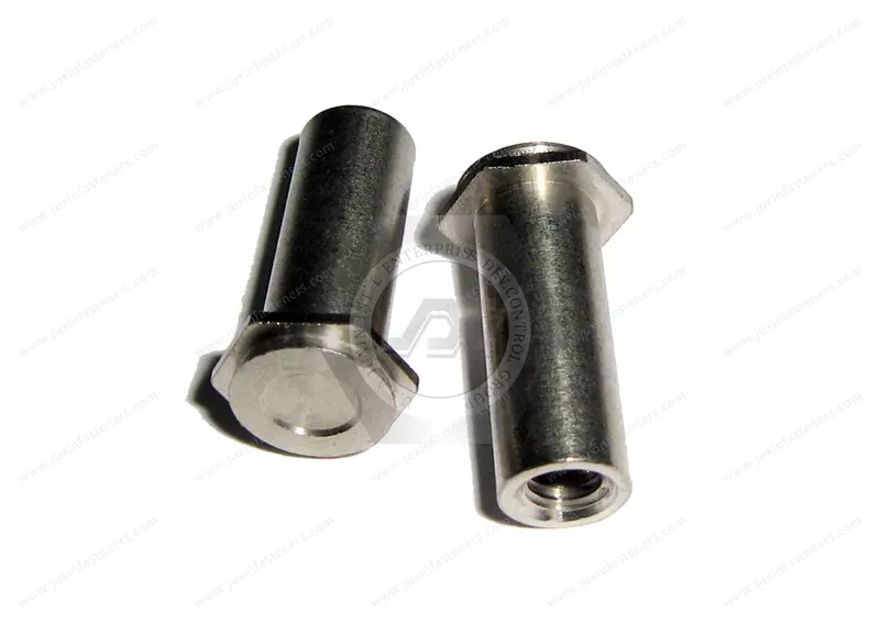
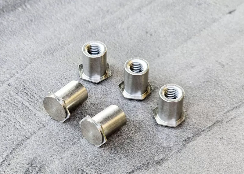
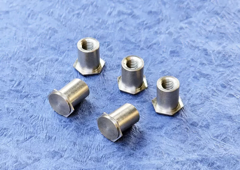
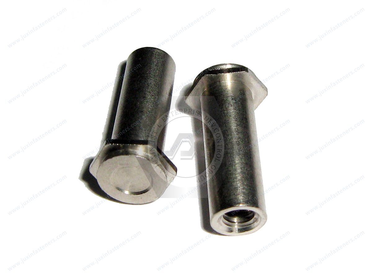
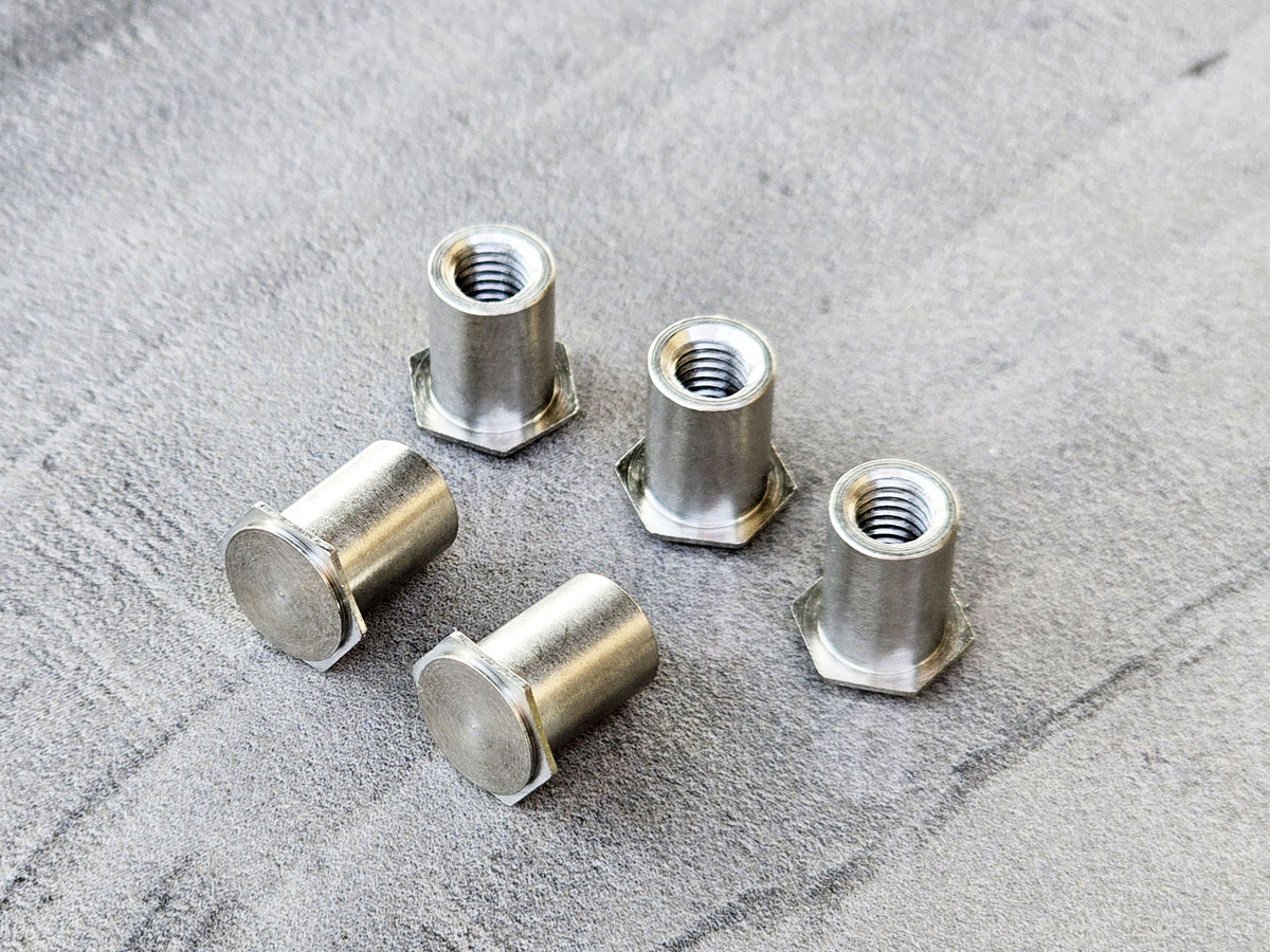
JUXIN FASTENERS supplies concealed-head self-clinching standoffs, Types JX-CSOS and JX-CSS, for permanent threaded mounting in sheet-metal assemblies where the opposite panel surface must remain smooth, intact, and unmarred.
These stainless steel standoffs are designed for installation into precision-milled blind holes in metal sheets as thin as 0.062 in. (approximately 1.57 mm), subject to the approved product dimensions and installation requirements. During press installation, displaced sheet metal flows around the fastener head and into its undercut, creating a secure mechanical interlock without penetrating or marking the opposite side of the panel.
Installation uses a properly prepared blind hole, a hollow support anvil, a solid punch, and a suitable standard press. The concealed-head configuration provides permanent threaded mounting points for electronic enclosures, industrial control cabinets, equipment chassis, precision sheet-metal assemblies, and other OEM applications requiring an uninterrupted exterior surface.
Available thread sizes identified for the product family range from #4 through 1/4 in. and M3 through M6. Stainless steel material options include SUS302, SUS303, SUS316, SUS410, SUS420, and SUS430, subject to model-specific engineering confirmation.
Custom dimensions and application-specific configurations may be evaluated against customer drawings and approved technical specifications.
Product Specification
Concealed-Head Self-Clinching Standoffs for Flush Sheet-Metal Assemblies and OEM Equipment
Product Overview
Concealed-head self-clinching standoffs are specialized threaded mounting components designed for permanent installation into sheet-metal panels without creating a visible fastener head or mounting hole on the opposite surface.
JUXIN FASTENERS supplies the JX-CSOS and JX-CSS series for industrial assemblies requiring concealed attachment points, controlled component spacing, and a smooth external panel appearance.
These standoffs are designed to provide permanent mounting in metal sheets as thin as 0.062 in. (approximately 1.57 mm), provided that the selected fastener, sheet material, blind-hole geometry, and installation conditions meet the applicable engineering specifications.
Unlike conventional through-hole standoffs, concealed-head versions are installed into precision-milled blind holes. The fastener head is mechanically locked within the panel, while the threaded standoff body projects from the installation side to provide a mounting point for another component.
The concealed-head design is particularly valuable where external surfaces must remain uninterrupted for appearance, clearance, handling, or assembly integration.
Typical applications include electronic enclosures, industrial equipment panels, sheet-metal chassis, control systems, and precision OEM assemblies.
What Is a Concealed-Head Self-Clinching Standoff?
A concealed-head self-clinching standoff is a mechanically retained threaded spacer installed into a blind hole in a metal panel.
Its head incorporates retention geometry that allows surrounding sheet material to flow into an undercut during press installation.
Once properly installed, the displaced material mechanically captures the fastener head and creates a secure connection capable of supporting substantial mechanical loads when the application, substrate, and installation conditions are appropriately engineered and validated.
The actual allowable load depends on the fastener configuration, sheet material, installation geometry, and verified retention performance. No universal load rating should be assumed without supporting test data.
The standoff body provides a threaded mounting location for screws, brackets, circuit boards, equipment modules, or other supported components.
The blind-hole installation prevents the fastener head from breaking through the opposite panel surface.
This design allows engineers to create permanent mounting points while preserving the appearance and physical continuity of the external sheet-metal surface.
The component is not a welded stud, adhesive insert, or conventional screw-mounted spacer. Its retention depends on correct hole preparation, compatible sheet material, and controlled mechanical installation.
Product Series and Available Configurations
Product family: Concealed-head self-clinching standoffs
JUXIN series: JX-CSOS and JX-CSS
Fastening principle: Mechanical retention through sheet-metal displacement into the fastener head undercut
Installation method: Press installation into a precision-milled blind hole
Mounting function: Permanent threaded spacing and component attachment
Minimum referenced sheet thickness: 0.062 in. (approximately 1.57 mm)
Metric thread range: M3 to M6
Inch thread range: #4 through 1/4 in., subject to the applicable product drawing
Material family: Stainless steel
Custom dimensions: Subject to drawing review and manufacturing feasibility
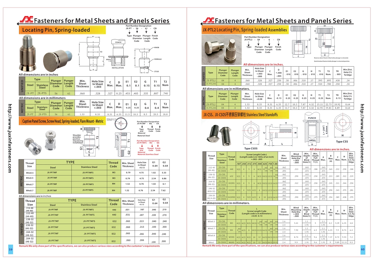
Technical reference: Product specification PDF and CAD documentation, pages 59–60
The listed thread ranges represent the supplied product-family information. Individual thread sizes, standoff lengths, head dimensions, and installation requirements must be verified for the selected JX-CSOS or JX-CSS configuration.
The available information does not establish a complete dimensional distinction between JX-CSOS and JX-CSS. Buyers should identify the required series and obtain the corresponding approved drawing before ordering.
Stainless Steel Material Options
The supplied product information identifies the following stainless steel grades as potential material options:
SUS302
SUS303
SUS316
SUS410
SUS420
SUS430
These grades have different metallurgical characteristics and should not be considered automatically interchangeable.
Austenitic Stainless Steel
Grades such as 302, 303, and 316 belong to the austenitic stainless steel family.
303 is commonly selected for applications where machinability is an important consideration, while 316 is frequently considered for environments requiring improved resistance to certain corrosive conditions.
Material suitability depends on the actual operating environment, mechanical requirements, manufacturing process, and required finished condition.
Martensitic and Ferritic Stainless Steel
410 and 420 are martensitic stainless steel grades, while 430 is ferritic stainless steel.
These grades differ in hardenability, mechanical properties, corrosion behavior, and forming characteristics.
For self-clinching applications, the hardness relationship between the fastener and the sheet material is particularly important.
A suitable material grade alone does not establish installation compatibility.
The selected fastener material, processing condition, surface treatment, and sheet hardness must be evaluated together.
International Material Specifications
Where applicable, OEM material requirements may reference recognized ASTM, SAE, EN, or other internationally accepted specifications.
A nominal SUS designation should not automatically be treated as proof of compliance with a specific ASTM or EN grade.
Equivalent material selection must be based on the required chemical composition, mechanical properties, processing condition, and applicable specification.
The final material designation and any requested material documentation should be confirmed during engineering approval and purchasing.
Concealed-Head Installation Principle and Mechanical Interlock
The defining feature of this fastening system is the mechanical interlock formed between the concealed fastener head and the surrounding sheet material.
The fastener head is positioned inside a precision-milled blind hole, rather than passing through the full thickness of the panel.
During installation, controlled press force causes the surrounding sheet metal to flow into the undercut beneath the fastener head.
This material displacement locks the head securely within the panel and provides resistance to axial displacement and rotation, subject to the validated installation and loading conditions.
Because the blind hole does not penetrate the opposite surface, the reverse side of the panel remains smooth and unmarred when the installation is performed correctly.
This feature is particularly important for precision enclosures, exterior equipment panels, and mechanical assemblies where visible fastener heads or surface protrusions are unacceptable.
The connection is created through mechanical deformation rather than welding, adhesive bonding, or conventional threaded attachment to the panel.
Engineering performance depends on the interaction between the fastener geometry, sheet material properties, hole preparation, and installation process.
Blind-Hole Preparation Using Center-Cutting End Mills
Sheet preparation for concealed-head standoffs requires a precision-milled blind hole to the minimum depth and diameter specified in the approved product drawing.
Center-cutting end mills are suitable for preparing the required blind-hole geometry when the selected cutting tool and machining process meet the dimensional requirements.
JUXIN FASTENERS identifies center-cutting end mills as an available hole-preparation tooling option. Specific tool sizes and supply availability should be confirmed during technical inquiry.
Unlike a punched through-hole, a blind hole must be machined without penetrating the opposite surface of the panel.
The hole must provide sufficient space for the concealed fastener head while retaining adequate material beneath and around the installation area.
Critical machining requirements include:
Accurate blind-hole diameter
Controlled hole depth
Adequate remaining panel thickness
Proper hole-bottom geometry
Burr-free machining
Consistent surface condition
Correct alignment with the intended mounting location
An incorrectly machined blind hole may reduce mechanical retention, prevent full head seating, or cause unwanted deformation of the opposite panel surface.
For high-volume OEM production, hole preparation should be controlled through approved machining parameters and appropriate dimensional inspection.
Press Installation Using a Hollow Anvil and Solid Punch
The supplied product installation method uses a hollow anvil and a solid punch with a suitable standard press.
The hollow anvil supports the assembly while providing clearance for the projecting standoff body.
The solid punch applies controlled installation force to seat the concealed head within the prepared blind hole.
The basic installation sequence is as follows.
Prepare the blind hole according to the approved dimensional specifications.
Remove machining debris and verify the hole geometry.
Position the concealed fastener head inside the blind hole.
Arrange the workpiece and fastener between the properly aligned solid punch and hollow support anvil.
Apply controlled press force using suitable press equipment.
Allow the surrounding sheet material to flow around the fastener head and into the undercut.
Complete installation when the required seating condition is achieved.
Inspect the installed fastener for correct position, mechanical retention, and an unmarred opposite panel surface.
A conventional mechanical or hydraulic press may be suitable when it provides the necessary force control, alignment, tooling support, and repeatability.
Installation force should not be selected arbitrarily.
Excessive force can deform the sheet or damage the fastener, while insufficient force may prevent complete material flow into the undercut.
The correct installation parameters must be established from the product drawing, material combination, and production validation.
Flush and Unmarred Opposite-Surface Design
One of the primary advantages of concealed-head self-clinching standoffs is the ability to preserve a smooth panel surface opposite the installation.
Because the mounting hole is blind rather than through, the concealed fastener head does not emerge on the reverse side of the sheet.
When the hole depth, remaining material thickness, and installation force are correctly controlled, the opposite surface can remain free from visible fastener heads, penetration marks, and unacceptable deformation.
This characteristic is useful where exterior appearance, component clearance, sealing interfaces, or mechanical movement requires an uninterrupted surface.
However, a concealed-head installation should not automatically be treated as a certified pressure-tight, liquid-tight, or hermetic seal.
Any sealing or environmental protection requirement must be evaluated separately within the complete enclosure design.
Sheet Thickness and Panel Compatibility
The referenced product family is described as suitable for permanent mounting in metal sheets as thin as 0.062 in., approximately 1.57 mm.
This minimum thickness is subject to the selected standoff configuration and approved installation requirements.
The allowable sheet thickness depends on the concealed head dimensions, required blind-hole depth, remaining material thickness, and mechanical loading conditions.
The sheet material must be sufficiently ductile to flow into the fastener head undercut during press installation.
Material hardness is therefore a critical design consideration.
A panel that is too hard may resist the required material displacement and fail to develop adequate mechanical retention.
A panel that is too thin may deform or become marked on the opposite surface during installation.
The suitability of stainless steel, aluminum, or other sheet materials should be evaluated using the selected fastener drawing and representative installation testing.
No universal maximum sheet hardness or installation-force value has been verified from the supplied information.
These values must be established for the actual product and substrate combination.
Metric and Inch Thread Options
The supplied product-family information identifies metric thread sizes from M3 to M6 and inch-thread sizes from #4 through 1/4 in.
Metric configurations may be suitable for equipment designed around ISO metric screw threads.
Inch-thread configurations may be suitable for assemblies using Unified thread systems.
The exact thread designation must be confirmed for each ordered part.
For example, an M4 threaded standoff is not directly interchangeable with a #8 Unified threaded standoff.
Likewise, an M6 thread cannot be substituted directly for a 1/4-inch Unified thread.
Thread diameter, pitch, fit class, usable engagement length, and mating screw requirements must be evaluated separately.
Engineers should also confirm whether the selected standoff configuration provides a through-threaded or blind-threaded body.
The approved drawing must establish the applicable thread form, standoff length, usable thread depth, and dimensional tolerances.
Industrial Applications and Engineering Solutions
Electronic Enclosures and Control Cabinets
Concealed-head self-clinching standoffs provide internal threaded mounting points while preserving the exterior appearance of metal enclosure panels.
Potential applications include control cabinets, instrument housings, industrial electronics enclosures, and removable equipment covers.
The standoffs can support brackets, mounting plates, electronic modules, and other internal components where threaded attachment is required.
Engineers should verify component weight, vibration exposure, grounding requirements, and the mechanical strength of the complete mounting arrangement.
PCB Mounting and Electronic Equipment Spacing
Threaded standoffs are commonly used to establish controlled separation between printed circuit boards and supporting chassis structures.
Concealed-head configurations may be appropriate when the outer surface of the chassis must remain smooth.
The required standoff height should be selected according to board clearance, component geometry, assembly tolerance, and service requirements.
The fastening arrangement should also account for electrical clearance and any required insulation.
A stainless steel standoff should not automatically be assumed to provide electrical isolation.
AI Data Center and Server Equipment Enclosures
Precision sheet-metal assemblies used in server racks, power equipment, and electronic infrastructure may require concealed internal mounting points.
Potential applications include mounting brackets, equipment subassemblies, control electronics, and serviceable chassis components.
The concealed-head design can be useful where exterior panels require an uninterrupted surface or where conventional through-hole attachment would interfere with adjacent components.
Mechanical loading, vibration, installation access, and production consistency must be evaluated for the intended equipment.
Power Electronics and Electrical Equipment
Power conversion equipment, industrial controllers, UPS assemblies, and electrical distribution enclosures frequently incorporate internal brackets, circuit boards, and mechanical support components.
Concealed-head standoffs may provide threaded attachment points where the exterior panel must remain free of visible fastener heads.
Selection should account for operating temperature, material compatibility, component clearance, electrical spacing, and maintenance accessibility.
Electrical or thermal performance must be evaluated within the complete equipment design.
Industrial Automation and Machinery
Automation systems often incorporate precision sheet-metal covers, instrument panels, machine housings, and modular mechanical assemblies.
Concealed-head standoffs may support internal brackets and components without introducing protrusions on the opposite panel surface.
This can be useful where external clearance, operator access, or component movement is important.
For production equipment, mounting strength and assembly repeatability should be validated under representative operating conditions.
Medical and Laboratory Equipment Housings
Laboratory instruments and precision equipment may require smooth external surfaces and internal threaded mounting points.
Concealed-head standoffs can be considered for suitable mechanical enclosure applications.
However, compatibility with regulated equipment, specialized cleaning processes, or controlled environments requires separate engineering and regulatory assessment.
The product should not be represented as medically certified without supporting documentation.
EV Electronics and Battery-System Enclosures
Electric vehicle electronics and battery-related equipment can incorporate sheet-metal housings, internal mounting brackets, and electrical control assemblies.
Concealed-head standoffs may be evaluated for appropriate mounting functions where the design requires an uninterrupted panel surface.
Material compatibility, vibration, thermal cycling, environmental exposure, and electrical clearance should be considered.
Structural battery retention, crash-loading, or safety-critical applications require separate design validation and documented performance requirements.
Semiconductor and Precision Industrial Equipment
Semiconductor equipment and precision industrial machinery may use enclosed control systems, sheet-metal housings, and internal support structures.
Concealed-head standoffs can be considered where internal threaded mounting is required without exposing the attachment feature on the opposite surface.
Material cleanliness, corrosion behavior, particle generation, and installation repeatability should be evaluated where relevant.
Specialized cleanroom or vacuum compatibility must not be assumed from the stainless steel material designation alone.
Mechanical Performance and Retention Considerations
The mechanical interlock formed between the fastener head and the displaced sheet metal can provide substantial retention when the installation geometry and material combination are properly engineered.
However, the available information does not establish verified numerical load ratings.
Engineering evaluation should therefore consider the following characteristics.
Axial Pushout Resistance
Pushout resistance describes the force required to displace the installed fastener axially from the panel under a defined test condition.
The result depends on fastener geometry, sheet material properties, blind-hole preparation, and installation quality.
Torque-Out Resistance
Torque-out resistance describes the installed fastener's resistance to rotation when torque is applied through the threaded connection.
This is important during screw tightening and repeated assembly operations.
Panel Deformation and Local Material Failure
The complete joint should be evaluated for possible panel deformation, local material failure, or fastener separation under the intended loading conditions.
The allowable load cannot be established solely from the nominal thread size.
Vibration and Repeated Assembly
Repeated screw installation, equipment vibration, and maintenance cycles can influence joint performance.
Appropriate screw tightening procedures, mating component design, and application-specific testing should be established.
No numerical pushout, torque-out, pull-through, or fatigue values should be assigned without supporting test data.
Concealed-Head Standoffs Compared with Alternative Mounting Methods
Concealed-Head Standoffs vs. Standard Self-Clinching Standoffs
Standard self-clinching standoffs are often preferred where a conventional prepared through-hole is acceptable.
Concealed-head standoffs are more appropriate where the opposite panel surface must remain intact.
The concealed-head design may require additional blind-hole machining and tighter process control.
Concealed-Head Standoffs vs. Welded Standoffs
Welded standoffs provide an alternative method of permanent attachment.
However, welding can introduce localized heat, distortion, discoloration, and additional finishing requirements.
Concealed-head press installation avoids a welding operation, although it requires compatible sheet material and correctly prepared blind holes.
Concealed-Head Standoffs vs. Rivet Nuts
Rivet nuts are generally designed to provide threaded attachment in prepared holes, often with access from one side.
They serve a different installation purpose and do not automatically provide the same concealed reverse-side appearance.
The appropriate solution depends on panel access, available thickness, mounting geometry, and required retention.
Concealed-Head Standoffs vs. Adhesive-Bonded Spacers
Adhesive-bonded spacers may avoid some mechanical installation operations.
However, adhesive performance depends on surface preparation, curing conditions, environmental exposure, and long-term joint requirements.
Mechanically retained concealed-head standoffs use a different attachment principle and should be selected according to the actual application requirements.
Manufacturing Process and Production Efficiency
For production managers and manufacturing engineers, the cost of a concealed-head standoff should be evaluated as part of the complete installation process.
Relevant cost factors include blind-hole machining time, cutting tool selection, inspection requirements, press setup, installation cycle time, and rejection risk.
A concealed-head standoff may reduce the need for visible fastener heads or additional cosmetic finishing in suitable equipment designs.
However, it may require more machining than a conventional through-hole self-clinching standoff.
The preferred solution depends on production volume, panel geometry, required surface finish, and assembly process capability.
For repeat production, engineering teams should establish a controlled installation procedure.
This may include incoming fastener inspection, hole-depth verification, press tooling qualification, installed-height inspection, and functional testing.
Where required by the customer, the installation process may be incorporated into a first-article inspection or production validation plan.
Common Installation Problems and Prevention
Incorrect Blind-Hole Depth
A hole that is too shallow may prevent proper head seating.
A hole that is too deep may leave insufficient material beneath the fastener head.
Both conditions can compromise installation quality.
Oversized Mounting Hole
An oversized hole may reduce the amount of material available to flow into the fastener undercut.
This can affect mechanical retention.
Excessive Installation Force
Uncontrolled press force may damage the fastener, distort the panel, or mark the opposite surface.
Installation parameters must be established for the specific material and product configuration.
Insufficient Material Displacement
If the panel material does not flow adequately into the undercut, the fastener may not achieve the intended retention.
This may result from unsuitable material hardness, incorrect hole geometry, or improper installation tooling.
Tooling Misalignment
Misaligned punch and anvil tooling can introduce uneven loading or component deformation.
Production tooling should maintain the required alignment and support.
Surface Damage on the Opposite Side
One of the principal reasons for selecting a concealed-head standoff is to preserve the opposite surface.
Inspection should therefore include verification that the panel remains smooth and free of unacceptable distortion or marking.
OEM Engineering Selection Checklist
Before specifying JX-CSOS or JX-CSS concealed-head standoffs, the design engineer should confirm the required thread size and thread system, standoff length, panel material, panel hardness, and minimum and maximum sheet thickness.
The engineering review should also establish the blind-hole diameter and depth, remaining panel thickness beneath the hole, installation punch and anvil geometry, required pushout and torque-out performance, expected screw tightening torque, operating temperature, and environmental exposure.
Surface appearance requirements, production volume, installation methods, and inspection documentation should be included in the design approval process.
The final product selection should be supported by the applicable technical drawing and validated installation conditions.
OEM Purchasing and Supplier Qualification
JUXIN FASTENERS supports technical inquiries from OEM manufacturers, Tier-1 and Tier-2 suppliers, purchasing engineers, supplier development teams, and industrial procurement organizations.
For efficient sourcing and technical evaluation, buyers should provide the applicable product designation and approved drawing.
The RFQ should identify the required material grade, thread size, standoff length, installation panel specification, and dimensional tolerances.
Where a customer requires specific quality documentation, dimensional inspection, material traceability, or first-article reporting, these requirements should be communicated during quotation.
Supplier qualification should also consider production consistency, drawing revision control, packaging identification, delivery requirements, and the ability to support repeat orders.
Custom manufacturing feasibility, inspection scope, and commercial terms should be confirmed before production commitment.
Custom Concealed-Head Standoff Manufacturing and RFQ Requirements
Customer-specific concealed-head standoffs may be evaluated where standard dimensions or material configurations do not satisfy the equipment design.
Potential customization requirements include metric or Unified thread specifications, standoff body length, head and undercut geometry, material grade, dimensional tolerances, surface finish, special installation requirements, customer-specific inspection criteria, packaging, and annual production demand.
The feasibility of each requested modification depends on the actual design, manufacturing process, tooling requirements, and application validation.
Customers are encouraged to provide 2D engineering drawings and available 3D CAD files for technical review.
Frequently Asked Questions
What is the main advantage of a concealed-head self-clinching standoff?
The primary advantage is the ability to create a permanent threaded mounting point while keeping the opposite sheet-metal surface smooth and unmarred.
How is a concealed-head standoff installed?
The fastener head is placed into a precision-milled blind hole and installed using controlled press force with a suitable solid punch and hollow support anvil. Sheet material flows into the head undercut to create mechanical retention.
Can concealed-head standoffs be installed in 0.062-inch sheet metal?
The supplied product information identifies applications in metal sheets as thin as 0.062 in., approximately 1.57 mm. Actual compatibility depends on the selected fastener, panel material, blind-hole geometry, and approved installation specifications.
Do concealed-head standoffs require special hole preparation?
Yes. A precision-milled blind hole is required. Center-cutting end mills may be used to produce the specified hole geometry. The diameter, depth, and remaining panel thickness must comply with the approved drawing.
What installation tools are required?
The supplied installation method uses a suitable standard press, a solid punch, and a hollow anvil. The tooling must be compatible with the selected fastener dimensions and panel geometry.
What thread sizes are available?
The supplied product-family information identifies metric threads from M3 to M6 and inch-thread sizes from #4 through 1/4 in. Specific combinations must be verified against the applicable JX-CSOS or JX-CSS drawing.
Are concealed-head standoffs suitable for stainless steel panels?
Suitability depends on the hardness and deformation characteristics of the panel and the selected fastener. Stainless steel panel compatibility must be verified rather than assumed.
Do concealed-head standoffs require welding?
No. The referenced design uses mechanical retention created by press installation into a prepared blind hole.
What is the difference between JX-CSOS and JX-CSS?
Both are identified as concealed-head stainless steel standoff series. Their exact dimensional and material differences must be confirmed from the respective product drawings before selection.
Can JUXIN FASTENERS review custom standoff drawings?
Customer-specific dimensions and requirements may be submitted for engineering review. Manufacturing feasibility, tooling, material selection, and final specifications must be confirmed before quotation.
What information should a purchasing engineer include in an RFQ?
An effective RFQ should include the product model, drawing, thread specification, standoff length, material grade, panel details, order quantity, annual demand, quality requirements, and delivery expectations.
Related Self-Clinching Fasteners and Sheet-Metal Hardware
For additional sheet-metal assembly requirements, consider the following related JUXIN FASTENERS product families:
Standard Self-Clinching Standoffs
Blind-Threaded Self-Clinching Standoffs
Self-Clinching Nuts for Sheet Metal
Self-Clinching Studs
Flush-Head Self-Clinching Studs
Captive Panel Screws and Panel Fasteners
These related products provide alternative or complementary fastening functions for industrial enclosures, electronic assemblies, and precision sheet-metal structures.
The appropriate product should be selected according to installation access, panel thickness, mounting requirements, and mechanical performance.
Contact JUXIN FASTENERS for Concealed-Head Standoff RFQs
JUXIN FASTENERS supplies industrial fastening components for OEM manufacturers, equipment builders, purchasing teams, and international industrial supply chains.
For concealed-head self-clinching standoffs, Types JX-CSOS and JX-CSS, our team can review product drawings, material requirements, installation specifications, and purchasing quantities.
We welcome inquiries involving standard product configurations, custom threaded standoffs, repeat production orders, and project-specific fastening requirements.
To request an engineering review or commercial quotation, please provide your technical drawings, material specifications, estimated order quantity, and delivery requirements.
Email: info@juxinfasteners.com
Website: www.juxinfasteners.com
Contact JUXIN FASTENERS to discuss concealed-head standoff selection, OEM supply requirements, and custom sheet-metal fastening solutions.
Product Packaging
JUXIN FASTENERS provides protective packaging for concealed-head self-clinching standoffs and other precision industrial fastening components.
The supplied packaging arrangement includes inner polyfoam protection, outer corrugated cartons, and palletized packing for transportation.
Reference carton dimensions:
29 × 19 × 19.5 cm
23.5 × 17.5 × 8 cm
Reference pallet dimensions:
215 × 100 × 90 cm
These dimensions are reference packaging configurations and may vary according to product dimensions, order quantity, and shipment requirements.
Customer-specific packaging arrangements may be reviewed for OEM and industrial supply programs, including protective separation, part-number identification, carton labeling, lot identification, and customer-defined packing instructions.
Final packing quantities, carton dimensions, pallet arrangements, and labeling requirements are confirmed according to the approved purchase order and shipment specifications.
Product Pictures
Contact Us
Tel.:
+86 020 8621 0320
+86 020 3121 6067
E-mail:
Technical Support:
Navigation
SEND INQUIREY