Call Us
+86 136 6007 9809
Call Us
+86 136 6007 9809

Structural High-Strength Blind Rivets
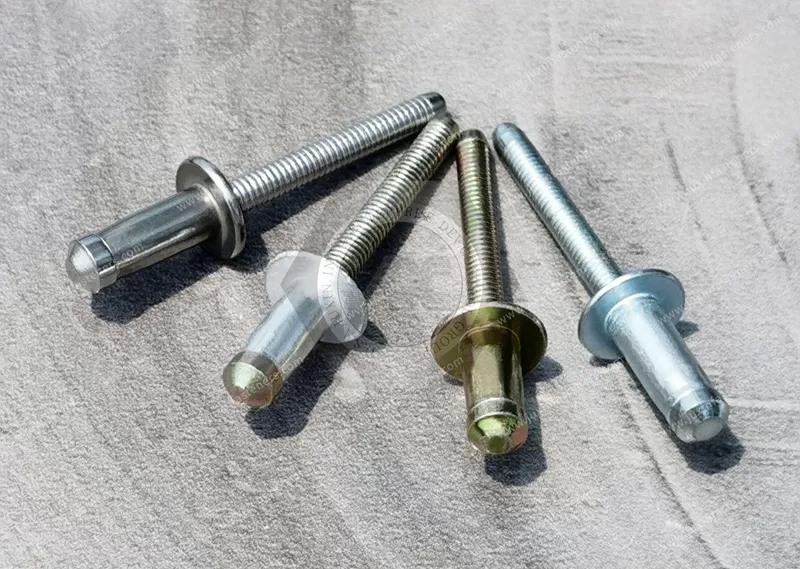
JUXIN FASTENERS supplies structural blind rivets for engineering evaluation in industrial sheet-metal and equipment assemblies,
with three material combinations: steel body/steel mandrel, aluminum body/carbon steel mandrel, and stainless steel body/stainless steel mandrel.
Structural blind rivet designs are intended for demanding one-sided fastening applications.
Depending on the specific design, features may include mechanical mandrel locking, increased shear and tensile capacity, improved clamp-up and controlled blind-side formation.
Actual locking mechanism, grip range, strength, head style, tooling and application suitability must be confirmed against the approved product drawing and test data.
Product Specification
Structural High-Strength Blind Rivets for OEM and Industrial Assemblies
Product Overview
JUXIN FASTENERS supplies structural high-strength blind rivets for OEM manufacturing, industrial sheet-metal fabrication, equipment assemblies and applications requiring one-sided access to the joint.
Structural blind rivets are a category of break-mandrel fasteners designed for demanding mechanical connections.
Compared with general-purpose blind rivets, selected structural designs may provide increased shear and tensile load capacity, enhanced mandrel retention, improved clamp-up and controlled blind-side formation.
The original JUXIN product information identifies three material combinations:
Steel rivet body with steel mandrel
Aluminum rivet body with carbon steel mandrel
Stainless steel rivet body with stainless steel mandrel
The specific performance of each configuration depends on its rivet geometry, material grades, mandrel design, locking mechanism, installation tooling and approved test results.
Not all structural blind rivets use the same locking system, head style, grip range or installation process.
Product Specifications and Material Configurations
| Item | Specification |
|---|---|
| Product Name | Structural High-Strength Blind Rivets |
| Product Category | Structural / High-Strength Blind Rivets |
| Product Type | Structural Break-Mandrel Blind Rivet |
| Configuration A | Steel Body + Steel Mandrel |
| Configuration B | Aluminum Body + Carbon Steel Mandrel |
| Configuration C | Stainless Steel Body + Stainless Steel Mandrel |
| Installation Access | One-Sided |
| Setting Method | Mechanical Blind Riveting |
| Mandrel Locking Mechanism | Subject to product drawing verification |
| Head Style | Subject to selected product |
| Grip Range | Subject to selected product |
| Mechanical Strength | According to verified product data |
| Surface Finish | To be confirmed |
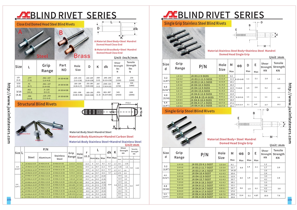
| Technical Reference | Original PDF/CAD, pages 105–106 |
Important Engineering Note
The material combinations listed above are taken from the original JUXIN product description.
Specific alloy grades, stainless steel grades, coatings, mechanical locking features and performance ratings have not been established from the available information.
The approved product drawing and verified test data must be used for final engineering selection.
Key Engineering Features
Depending on the selected structural rivet design, relevant characteristics may include:
One-sided installation
High-strength mechanical fastening
Structural break-mandrel construction
Mechanical mandrel locking
Retained mandrel contribution to joint performance
Controlled blind-side head formation
Increased clamp-up capability
Vibration-resistant joint design
Wide grip-range capability
Hole-filling capability
Compatibility with selected production riveting systems
These features are design-dependent and must not be assumed for every configuration.
Engineering Solution 1 — How Structural Blind Rivets Work
A structural blind rivet typically consists of a rivet body and a pull mandrel.
The rivet is inserted into a prepared mounting hole from the accessible side of the assembly.
A compatible installation tool grips and pulls the mandrel.
As the mandrel moves, the rivet body deforms on the inaccessible side, creating the blind-side retaining portion.
Depending on the rivet design, a locking mechanism may secure the retained mandrel within the rivet body.
The mandrel then breaks at its designed location.
This process produces a permanent mechanical joint without requiring rear-side tool access.
Structural blind rivets are normally installed by mechanical setting, not by heating the rivet shank until red-hot.
Traditional hot riveting is a different fastening process and should not be confused with structural break-mandrel blind riveting.
Engineering Solution 2 — Structural vs. Standard Blind Rivets
| Engineering Factor | Structural Blind Rivets | General-Purpose Blind Rivets |
|---|---|---|
| Primary Selection | Demanding mechanical connections | General sheet-metal fastening |
| Shear Capacity | Design-specific high-strength options | Product-specific |
| Tensile Capacity | Design-specific high-strength options | Product-specific |
| Mandrel Locking | Available in selected structural designs | Depends on design |
| Blind-Side Formation | Engineered for selected load requirements | Depends on design |
| Grip Range | Standard or multi-grip, depending on design | Standard or multi-grip |
| Tooling | May require specialized equipment | Depends on rivet |
| Qualification | Requires application-specific verification | Requires application-specific verification |
A structural designation does not automatically establish suitability for a safety-critical assembly.
The actual product must meet the required load, fatigue, environmental and installation criteria.
Engineering Solution 3 — Mechanical Mandrel Locking
Mechanical mandrel locking is an important characteristic of many structural blind rivet systems.
Depending on the product design, a retained mandrel may contribute to joint strength and help prevent loose mandrel components.
International structural rivet systems use different locking mechanisms, including internal and externally inspectable arrangements.
Important selection questions include:
Is the mandrel mechanically locked?
Where is the locking feature located?
Does the locking mechanism require a special nosepiece?
Can correct locking be verified after installation?
What mandrel retention criteria apply?
Does the retained mandrel contribute to the shear plane?
What happens if the rivet is incorrectly set?
The original JUXIN product information mentions mandrel locking, but the precise mechanism must be verified from the technical drawing.
No proprietary locking design or guaranteed retention percentage is claimed.
Engineering Solution 4 — Shear Strength and Tensile Strength
Structural rivet selection requires separate evaluation of shear and tensile loading.
Shear loading acts primarily across the fastener and joint interface.
Tensile loading acts primarily along the fastener axis and may tend to separate the joined components.
The relevant mechanical characteristics include:
Minimum or typical ultimate shear load
Minimum or typical ultimate tensile load
Joint bearing strength
Head-side pull-through
Blind-side pull-through
Fatigue performance
Joint deformation
Installation consistency
Actual mechanical data must be obtained for the selected diameter, material combination and product design.
Strength values from another manufacturer's proprietary structural rivet must not be assigned to JUXIN products.
Engineering Solution 5 — Blind-Side Head Formation
During installation, the rivet body forms a retaining portion on the inaccessible side of the joint.
The geometry of this formed head affects load transfer and pull-through resistance.
Engineers should evaluate:
Blind-side head diameter
Formed head height
Material stack-up
Panel strength
Hole diameter
Clearance behind the panel
Rivet body deformation
Installation force
A larger blind-side bearing area may help reduce local stress in suitable sheet-metal assemblies.
However, the actual blind-side geometry must be verified for each structural rivet design.
Engineering Solution 6 — Clamp-Up Force and Joint Integrity
Some structural blind rivet systems are designed to generate significant clamp-up force.
Clamp-up can help maintain contact between the joined components.
However, clamp-up is not equivalent to guaranteed long-term preload.
Joint behavior may change due to:
Panel deformation
Surface embedding
Vibration
Thermal expansion
Material relaxation
Installation variation
Repeated loading
For demanding applications, engineers should evaluate the installed joint rather than relying only on the nominal rivet specification.
Engineering Solution 7 — Material Configuration A: Steel Body + Steel Mandrel
Steel/steel structural blind rivets may be considered for compatible steel sheet-metal and industrial equipment assemblies.
Relevant selection factors include:
Steel body grade
Steel mandrel grade
Mechanical strength
Protective coating
Installation force
Joint thickness
Vibration and fatigue
Environmental exposure
The original product information does not identify the steel grades or coating.
Therefore, no specific strength class, zinc coating or corrosion performance is claimed.
Engineering Solution 8 — Material Configuration B: Aluminum Body + Carbon Steel Mandrel
Aluminum-body structural rivets with carbon steel mandrels may be considered where lightweight construction and one-sided fastening are important.
The steel mandrel may influence installation characteristics and the mechanical behavior of the fastener.
However, an aluminum-body rivet should not automatically be assigned the same strength as a steel-body structural rivet.
Important engineering considerations include:
Aluminum alloy and temper
Carbon steel mandrel grade
Retained mandrel geometry
Galvanic corrosion
Installation force
Panel material
Mechanical load requirements
Vibration and fatigue
The complete rivet mass and joint performance should be evaluated rather than relying only on material density.
Engineering Solution 9 — Material Configuration C: Stainless Steel Body + Stainless Steel Mandrel
Stainless steel structural blind rivets may be considered for demanding assemblies requiring an appropriate combination of mechanical performance and corrosion resistance.
Relevant factors include:
Stainless steel body grade
Stainless steel mandrel grade
Environmental exposure
Chloride concentration
Mechanical loading
Tooling requirements
Galling or installation behavior
Inspection and traceability
The original product information does not specify A2, A4, 304 or 316 grades.
These grades must not be assumed without confirmation.
Stainless steel is not immune to all forms of corrosion.
Engineering Solution 10 — Material Selection Comparison
| Selection Factor | Steel / Steel | Aluminum / Carbon Steel | Stainless / Stainless |
|---|---|---|---|
| Rivet Body | Steel | Aluminum | Stainless Steel |
| Mandrel | Steel | Carbon Steel | Stainless Steel |
| Relative Mass | Geometry-dependent | Geometry-dependent | Geometry-dependent |
| Mechanical Capacity | Product-specific | Product-specific | Product-specific |
| Corrosion Performance | Grade and coating dependent | Alloy and environment dependent | Grade and environment dependent |
| Galvanic Compatibility | Must be evaluated | Must be evaluated | Must be evaluated |
| Installation Force | Requires verification | Requires verification | Requires verification |
| Suitable Environment | Application-dependent | Application-dependent | Application-dependent |
No material combination should be selected solely from the general category name.
Engineering Solution 11 — Grip Range and Material Stack-Up
The selected rivet must accommodate the total thickness of the joined components.
A structural blind rivet may have a conventional grip range or a wider multi-grip capability, depending on the design.
Before selection, confirm:
Minimum material stack-up
Maximum material stack-up
Rivet diameter
Rivet body length
Head geometry
Hole diameter
Blind-side clearance
Required mechanical loads
An incorrectly selected grip range can prevent proper installation and reduce joint reliability.
Engineering Solution 12 — Hole Filling and Hole Tolerance
Certain structural blind rivets are designed to expand and improve hole filling during installation.
This may help manage controlled hole variation in specific assemblies.
However, not all structural rivets are suitable for oversized, slotted or misaligned holes.
Engineers should verify:
Minimum hole diameter
Maximum hole diameter
Hole roundness
Hole alignment
Burr condition
Hole-to-edge distance
Rivet spacing
Required hole-filling behavior
Hole tolerances must follow the approved product and assembly drawings.
Engineering Solution 13 — Installation Tooling and Nosepiece Compatibility
Structural blind rivets may require higher setting forces or special installation equipment.
Some mechanical-lock structural rivets require dedicated nosepieces to form or verify the locking feature correctly.
Tooling selection should consider:
Required pulling force
Rivet diameter
Mandrel diameter
Nosepiece geometry
Stroke requirement
Tool access
Mandrel collection
Cycle time
Production volume
Installation monitoring
A standard blind rivet tool should not be assumed compatible with every structural rivet.
Typical Installation Procedure
Confirm the selected structural rivet part number.
Review the approved engineering drawing.
Verify the material stack-up and grip range.
Prepare mounting holes within specified tolerances.
Inspect hole alignment and burr condition.
Select the approved riveting tool and nosepiece.
Insert the rivet from the accessible side.
Seat the rivet head correctly.
Pull the mandrel using the specified setting process.
Allow the blind-side retaining portion to form.
Complete the mandrel locking operation, where applicable.
Complete the mandrel break.
Inspect the installed head and lock condition.
Verify the joint against the approved inspection criteria.
Engineering Solution 14 — Vibration and Fatigue Resistance
Structural blind rivets may be selected for assemblies exposed to repeated mechanical loading.
However, vibration resistance depends on the complete joint design.
Important factors include:
Rivet material and geometry
Mandrel retention
Panel stiffness
Joint loading
Fastener spacing
Hole fit
Clamp-up
Temperature variation
Corrosion
Installation consistency
A structural rivet should not be described as vibration-proof.
Where fatigue is important, representative joint testing is required.
Engineering Solution 15 — Metric and Inch Diameter Reference
Common structural blind rivet diameter references include:
| Metric Diameter | Approximate Inch Reference |
|---|---|
| 4.8 mm | 3/16 in |
| 6.4 mm | 1/4 in |
| 9.5 mm | 3/8 in |
| 12.7 mm | 1/2 in |
These are general industry dimensional references, not confirmed available sizes for this JUXIN product.
Actual metric and inch-designated rivets must be checked for dimensional compatibility, grip range, hole diameter, strength and tooling requirements.
Industrial Applications and Engineering Fastening Solutions
Structural high-strength blind rivets may be evaluated for demanding OEM assemblies where one-sided installation and defined mechanical performance are required.
The following applications are potential engineering use cases. Suitability must be established for the actual joint and product.
1. Commercial Vehicle Manufacturing
Commercial vehicles may use metal equipment housings, brackets, body panels and auxiliary structures.
Structural blind rivets may be evaluated where mechanical loading, vibration and production efficiency are important.
Relevant requirements include:
Shear and tensile loads
Vibration
Fatigue
Corrosion
Panel thickness
Installation tooling
Inspection
Vehicle structural or safety-critical connections require specific engineering approval.
2. Automotive OEM and Tier-1 Assemblies
Automotive manufacturing may involve sheet-metal brackets, reinforcement components and equipment housings.
Structural blind rivets may be considered where the joint requires higher verified mechanical capacity than a general-purpose fastener.
Customer-specific material, fatigue, corrosion, quality and traceability requirements must be satisfied.
No automotive certification or PPAP capability is implied without project-specific confirmation.
3. EV Battery Enclosures and Auxiliary Structures
EV battery assemblies may contain metal housings, brackets and protective structures.
Structural blind rivets may be evaluated for appropriate mechanically loaded connections where one-sided access is required.
Engineers must consider:
Crash and impact requirements
Vibration and fatigue
Electrical isolation
Thermal cycling
Corrosion
Serviceability
Battery pack sealing
No suitability for crash-critical, coolant-containing or battery-pack structural joints is claimed without validation.
4. AI Data Center Equipment
AI data centers contain electrical cabinets, cooling equipment housings, power distribution systems and structural equipment supports.
Structural blind rivets may be considered for suitable metal brackets, covers and equipment frames.
Mechanical loading, electrical bonding, corrosion and maintenance requirements must be evaluated.
They should not be used as unqualified fluid-pressure seals or load-bearing building anchors.
5. Power Distribution Equipment
Power distribution equipment may include steel cabinets, reinforcement brackets and protective housings.
Structural blind rivets may be evaluated where reliable one-sided fastening is required.
Electrical clearance, bonding, vibration and equipment qualification requirements must be addressed.
6. Energy Storage Systems
Energy storage equipment may use metal cabinets, auxiliary reinforcement brackets and equipment housings.
Structural rivets may be considered for approved mechanical connections.
Thermal movement, vibration, corrosion and electrical isolation require evaluation.
7. Industrial Machinery
Industrial machinery may use heavy-duty covers, metal frames, protective guards and auxiliary brackets.
Structural blind rivets may be evaluated where the joint requires verified mechanical capacity and permanent fastening.
The design must account for cyclic loading, vibration and maintenance access.
8. HVAC and Industrial Ventilation Equipment
HVAC systems may include sheet-metal housings, support brackets and equipment frames.
Structural blind rivets may be considered where mechanical loading exceeds the intended capacity of general-purpose rivets.
Vibration, corrosion, airflow and assembly requirements must be evaluated.
9. Telecommunications Infrastructure
Telecommunications equipment may use outdoor metal cabinets, equipment brackets and support structures.
Structural blind rivets may be considered for approved connections requiring one-sided access.
Wind, vibration, corrosion and electrical bonding requirements must be verified.
10. Rail Transit Equipment
Rail equipment may include metal cabinets, auxiliary brackets and equipment housings.
Structural blind rivets may be evaluated for approved connections subject to project-specific requirements.
Vibration, fatigue, fire and smoke, traceability and safety approval must be considered.
11. Container and Trailer Manufacturing
Containers and trailers may use metal panels, brackets and equipment housings.
Structural blind rivets may be evaluated where joint loading and installation access make them appropriate.
Primary structural or regulated connections require separate engineering qualification.
12. Agricultural Machinery
Agricultural machinery may experience vibration, impact, dust and outdoor exposure.
Structural blind rivets may be considered for suitable brackets, covers and equipment panels.
Mechanical performance, corrosion and field serviceability must be reviewed.
13. Construction Equipment
Construction equipment may use metal housings, guards and auxiliary brackets.
Structural rivets may be evaluated where permanent one-sided fastening is required.
Impact, fatigue, corrosion and safety requirements must be assessed.
14. Semiconductor Equipment
Semiconductor equipment may contain metal frames, protective covers and auxiliary cabinets.
Structural blind rivets may be considered for approved non-process-critical connections.
Cleanliness, particle generation, electrical requirements and serviceability must be reviewed.
15. Marine and Offshore Auxiliary Equipment
Marine-related equipment may require corrosion-resistant fasteners for metal housings and auxiliary structures.
Stainless steel structural rivets may be evaluated where the actual alloy and environmental requirements are appropriate.
No seawater or offshore structural qualification is implied.
16. Aerospace Ground-Support Equipment
Ground-support equipment may use metal frames, tooling covers and auxiliary housings.
Structural blind rivets may be considered only where the approved engineering specification permits them.
No aircraft structural, flight-critical or aerospace certification is claimed.
Application Selection Matrix
| Engineering Requirement | Selection Guidance |
|---|---|
| High shear loading | Select using verified shear data |
| High tensile loading | Select using verified tensile data |
| Mechanical mandrel locking | Confirm locking mechanism and inspection |
| Wide grip range | Confirm actual multi-grip capability |
| Variable hole conditions | Verify permitted hole tolerance |
| Vibration | Validate complete joint fatigue performance |
| Lightweight assembly | Evaluate aluminum/steel configuration |
| Steel equipment fabrication | Evaluate steel/steel configuration |
| Corrosion-sensitive environment | Evaluate verified stainless grade or coating |
| High-volume production | Validate tooling, cycle time and inspection |
| Safety-critical assembly | Require separate qualification and approval |
Production Engineering — Quality Control
For production managers and manufacturing engineers, structural riveting requires consistent control of fastener identification, installation tooling and joint inspection.
Recommended production controls include:
Approved rivet part number
Material and coating verification
Rivet diameter and body length
Grip range
Mounting-hole diameter
Panel thickness
Tool and nosepiece identification
Setting force and stroke, where specified
Blind-side formation
Mandrel break condition
Locking feature inspection, where applicable
Joint deformation
Traceability
Sampling and test requirements
Where the joint is critical, the OEM should define a validated process and acceptance criteria.
Common Installation Problems and Engineering Checks
| Potential Problem | Engineering Check |
|---|---|
| Incomplete mandrel locking | Verify rivet design, tool and nosepiece |
| Loose joint | Review grip range and installation |
| Incomplete blind-side formation | Check material stack-up and tool stroke |
| Hole deformation | Review hole diameter and panel strength |
| Unexpected mandrel break | Check tooling and product configuration |
| Insufficient joint strength | Review load case and verified test data |
| Fatigue failure | Evaluate cyclic loading and joint design |
| Corrosion | Verify materials, coatings and exposure |
| Production inconsistency | Review tooling calibration and inspection |
International Standards and Technical Qualification
Structural blind rivets may be specified using manufacturer product standards, customer drawings and application-specific engineering requirements.
There is no single universal strength rating or locking mechanism that applies to every structural blind rivet.
The following must be established for the selected product:
Actual material grades
Rivet dimensions and tolerances
Grip range
Head style
Mechanical locking design
Minimum or typical shear and tensile performance
Installation tooling
Inspection requirements
Corrosion performance
Application-specific testing
Where ISO, DIN, EN, ASTM, SAE or customer-specific requirements apply, the actual product must be checked against the relevant specification.
Proprietary products such as Avdel Monobolt, Huck Magna-Lok and GESIPA G-Bulb have their own defined designs and performance data.
These names should not be used to imply that JUXIN supplies an identical or licensed product without verification.
OEM Procurement and Supplier Development
For purchasing managers, supplier development engineers and supply chain managers, structural rivet sourcing requires more information than nominal diameter and material.
A complete RFQ should identify:
Intended application
Rivet body material
Mandrel material
Material grades
Rivet diameter and length
Head style
Grip range
Mounting-hole dimensions
Required shear and tensile loads
Mandrel locking requirements
Fatigue and vibration requirements
Corrosion and environmental conditions
Tooling and nosepiece requirements
Inspection and traceability
Packaging specifications
Annual demand forecast
A visually similar structural rivet is not automatically interchangeable with another manufacturer's product.
Frequently Asked Questions
What is a structural blind rivet?
A structural blind rivet is a break-mandrel fastener designed for demanding mechanical connections and one-sided installation.
How is a structural blind rivet different from a standard blind rivet?
Selected structural designs offer higher verified mechanical capacity and may include mechanical mandrel locking, enhanced blind-side formation or other specialized features.
Do structural blind rivets require heating before installation?
No. Structural break-mandrel blind rivets are normally installed mechanically using compatible riveting tools.
Are all structural blind rivets mechanically locked?
Not necessarily. The locking mechanism must be confirmed for the specific rivet design.
Does the retained mandrel increase strength?
In certain structural designs, the retained mandrel contributes to mechanical performance. This must be verified for the selected product.
Are structural blind rivets vibration-resistant?
They may be designed for vibration-exposed applications, but the complete joint must meet the specified vibration and fatigue requirements.
Can structural rivets be installed in oversized holes?
Only where the specific rivet design and approved hole tolerances permit it.
Can a standard rivet gun install structural blind rivets?
Not always. Some designs require special tools or nosepieces.
What material combinations are identified for this JUXIN product?
Steel/steel, aluminum/carbon steel and stainless steel/stainless steel.
Are structural blind rivets suitable for EV battery packs?
They may be evaluated for suitable connections, but safety-critical, crash-related and fluid-boundary applications require separate engineering qualification.
Can JUXIN review custom structural blind rivet specifications?
Customer drawings, material requirements, dimensions and performance criteria can be submitted for technical review and quotation.
Request an OEM Structural High-Strength Blind Rivet Quotation
JUXIN FASTENERS supplies industrial fastening solutions for OEM manufacturing and bulk purchasing projects.
For engineering review and quotation, please provide:
2D engineering drawing or 3D CAD model
Rivet body and mandrel material requirements
Material grades and coatings
Rivet diameter and length
Head style and dimensions
Minimum and maximum grip thickness
Mounting-hole diameter and tolerance
Required shear and tensile strength
Mandrel locking requirements
Vibration and fatigue requirements
Environmental and corrosion requirements
Installation tool and nosepiece requirements
Inspection and traceability requirements
Packaging specifications
Estimated order quantity and annual demand
Target delivery schedule
Email: info@juxinfasteners.com
Website: https://www.juxinfasteners.com/
JUXIN FASTENERS — Structural High-Strength Blind Rivets and Custom OEM Fastening Solutions.
Product Packaging
Packaging Standard
At Juxin Fasteners, we apply standardized export packaging to ensure product protection, traceability, and compliance with international logistics requirements.
1. Standard Export Packaging
Unless otherwise specified, all products will be packed according to our factory standard export packaging, which includes:
Moisture-resistant inner protection
Poly bag or small box packing as required
Reinforced export cartons
Clear labeling with part number, specification, batch number, and quantity
Palletizing for sea or air shipment when necessary
Our standard packaging is designed to ensure safe transportation, efficient warehousing, and long-distance international shipping.
2. Customized Packaging Options
We also provide customized packaging solutions according to customer requirements, including but not limited to:
Private labeling
Customized barcodes
Specific carton dimensions
Retail packaging
Special pallet configuration
Customer-specific marking and identification
So that you know, customized packaging may involve additional costs and extended lead time depending on the complexity of the requirements.
3. Compliance & Quality Assurance
All packaging processes are controlled under our ISO 9001 quality management system to ensure consistency, traceability, and product integrity throughout the supply chain.
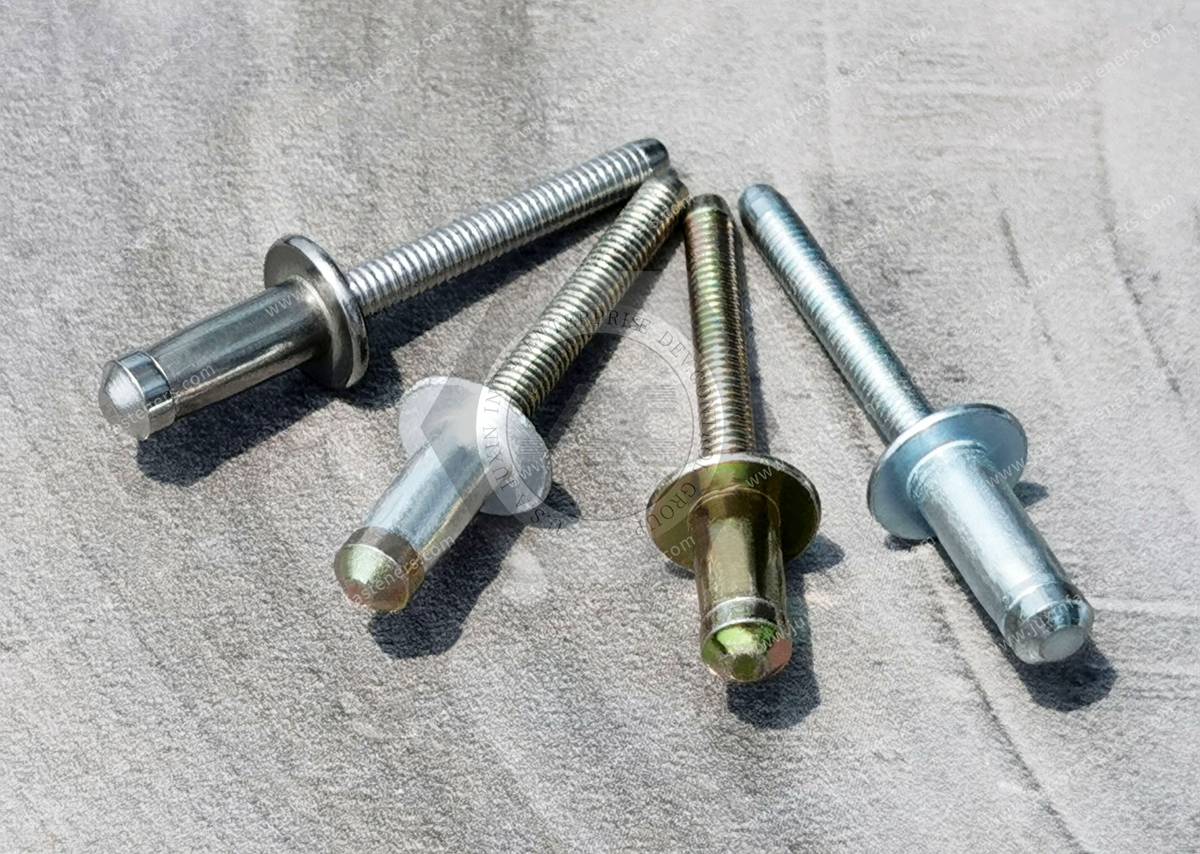
Product Pictures
Contact Us
Tel.:
+86 020 8621 0320
+86 020 3121 6067
E-mail:
Technical Support:
Navigation
SEND INQUIREY