Call Us
+86 136 6007 9809
Call Us
+86 136 6007 9809

Modern automotive manufacturing, electronic enclosure production, industrial machinery and equipment automation frequently
require threaded fastening points in restricted spaces or on thin-walled substrates.
Design engineers may need to attach brackets, covers, trim components,
access panels or internal hardware without adding a welded nut, tapping a thin panel or installing a conventional nut from the rear side.
Product Specification
Modern automotive manufacturing, electronic enclosure production, industrial machinery and equipment automation frequently require threaded fastening points in restricted spaces or on thin-walled substrates.
Design engineers may need to attach brackets, covers, trim components, access panels or internal hardware without adding a welded nut, tapping a thin panel or installing a conventional nut from the rear side.
In compact assemblies, the height of the fastener can be as important as its thread size. A protruding nut or clip may interfere with adjacent components,
wiring, insulation, moving parts or protective covers. A fastening component that is too loose for the panel thickness may also shift during assembly, while an unsuitable clip profile may produce inconsistent positioning.
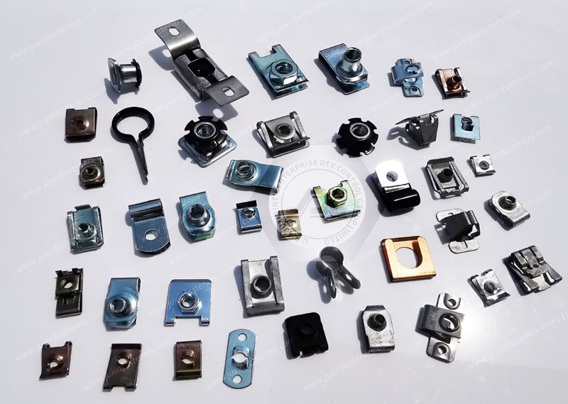
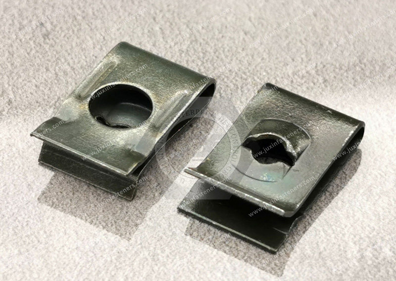
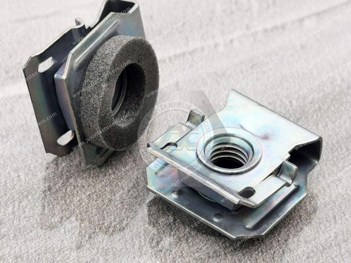
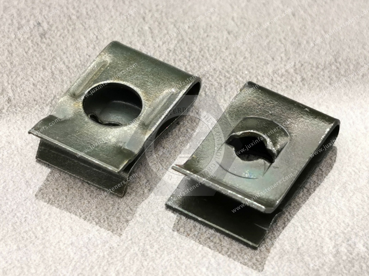
Low-Profile Strong-Grip Clip-On Nuts are designed for applications where a threaded nut is retained on a panel edge, flange, hole or mounting feature through a spring clip or formed carrier. Depending on the configuration, these products may be commercially described as low-profile clip nuts, barrel clip nuts, speed nuts, U-nuts, J-nuts, enclosed clip nuts or sheet-metal nuts.
These terms may describe related fastening architectures, but they do not define identical geometries or performance characteristics.
JUXIN FASTENERS supports OEM and industrial customers evaluating customized fastening components.
Product selection should be based on the required thread, panel thickness, mounting geometry, clearance, material, surface treatment, mating screw and application environment.
This guide examines low-profile clip-on nut configurations, installation mechanics, panel compatibility, anti-slip considerations, industrial applications and procurement requirements for engineering and supply chain teams.
Understanding the differences between clip-on nut designs is essential when the assembly has limited clearance or a specific panel interface.
The product’s nominal thread size is only one part of the selection process. The clip width, nut position, barrel length,
panel engagement and overall envelope can determine whether the component is suitable for the application.
Low-profile clip-on nuts are selected for applications where the available space around the fastening point is limited.
Potential design objectives include:
Reducing interference with adjacent components
Providing a threaded mounting point on thin sheet metal
Supporting assembly in restricted-access locations
Maintaining a compact component envelope
Allowing removal and replacement of the mating screw
Reducing the need for a separate rear-side nut
The phrase “flush-mount” should be used carefully. Some low-profile products reduce protrusion, but they may not be completely flush with the panel surface.
The actual result depends on the clip thickness, panel geometry and nut position.
Engineers should confirm the installed profile using the supplier’s dimensional drawing.
No-slip clip-on barrel nuts generally refer to designs intended to improve positioning or resistance to movement through their clip geometry, contact surfaces or retained nut body.
A barrel configuration may provide a different thread position or engagement length from a flat spring nut.
However, a deeper barrel does not automatically establish a higher pull-out rating, stronger shear resistance or universal vibration performance.
The selection should consider:
Barrel dimensions
Thread engagement
Panel thickness
Clip retention
Nut rotation
Screw access
Clearance behind the panel
Applied loads
The exact product architecture must be confirmed from the drawing.
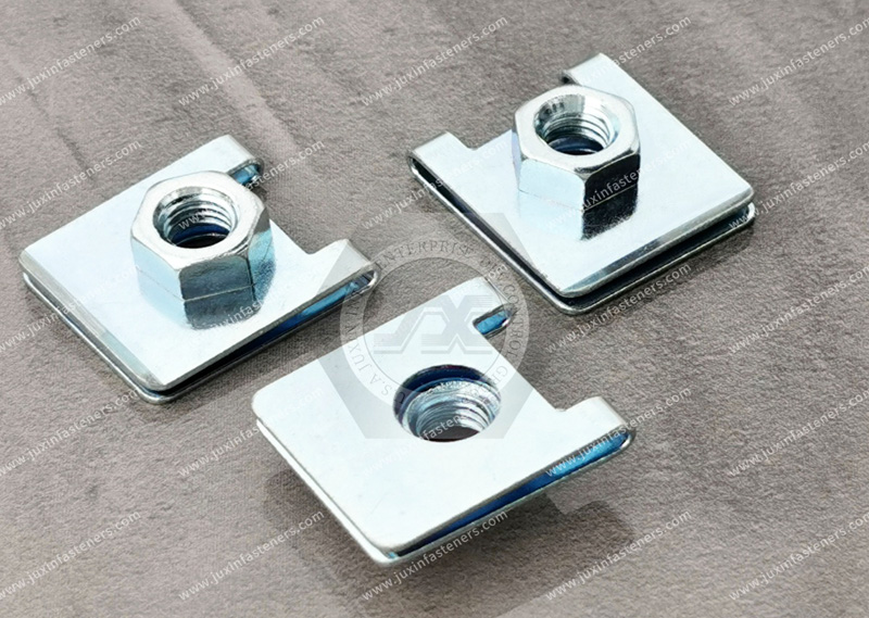
Some clip-on products retain a hexagonal nut inside a formed housing or carrier.
Potential advantages may include:
Controlled nut positioning
Reduced exposure of the nut body
A defined external profile
Improved handling during pre-assembly
Compatibility with selected panel geometries
An enclosed hex design should not automatically be described as stronger than every open clip design. Strength and retention depend on the material, geometry, panel interface and applied load.
Flanged-edge clip nuts are designed for mounting on specific panel edges, folded flanges or formed sheet-metal features.
Before selecting this configuration, the engineer should verify:
Flange thickness
Flange width
Edge accessibility
Clip opening
Nut alignment
Clearance around the flange
Required installation direction
A clip that fits a flat sheet edge may not fit a formed channel or reinforced flange.
Some spring clip products are designed for use with tapping screws or thread-forming screws rather than conventional machine screws.
The screw and nut design must be compatible. A tapping-screw clip nut may use a different internal geometry, material thickness or gripping arrangement from a machine-thread clip nut.
The RFQ should identify:
Screw type
Screw diameter or size
Thread-forming or thread-cutting function
Panel material
Required installation torque
Reuse expectations
Thread engagement requirements
A product intended for a tapping screw should not be substituted with a machine-thread nut without confirming compatibility.
Clip-on nuts are available in multiple product configurations, and no single standard necessarily covers every low-profile clip nut, barrel nut and enclosed clip design.
The applicable requirements may include:
Customer product drawings
Metric or inch thread standards
Material specifications
Spring component requirements
Surface-treatment specifications
Inspection requirements
Application-specific standards
SAE J891 is a relevant reference for spring nuts within its defined scope. It should not be presented as automatically applicable to every clip-on nut configuration.
For metric threads, applicable references may include ISO 261, ISO 262 and ISO 965, depending on the thread type and specified tolerance.
These references do not independently define the complete clip geometry, panel retention or vibration performance.
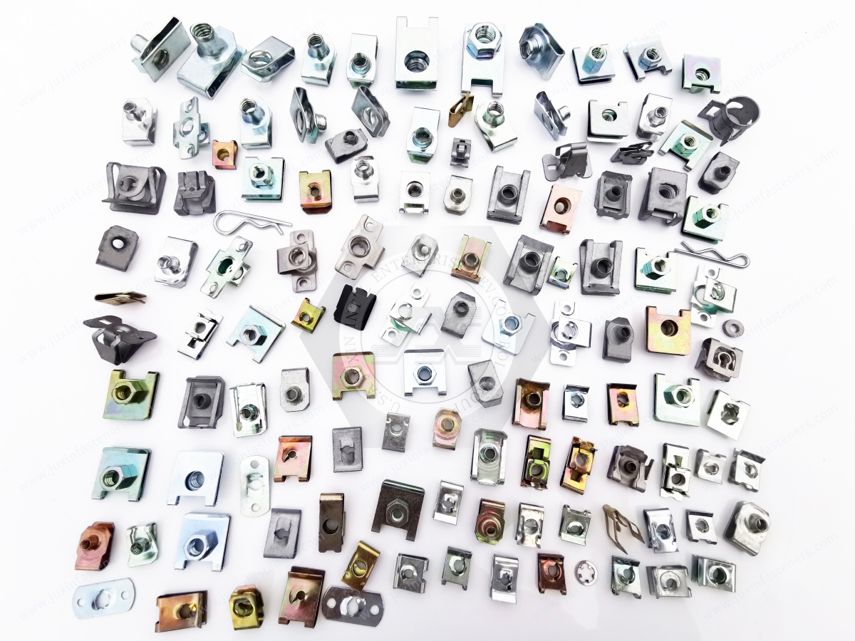
The following categories describe common design directions. The final product classification should be confirmed against the actual customer drawing and supplier configuration.
Operating concept: A compact clip-mounted threaded fastening point.
Potential applications:
Electronic equipment housings
Interior trim panels
Thin sheet-metal covers
Appliance panels
Industrial brackets
Primary selection considerations:
Overall installed height
Panel thickness
Clip retention
Thread compatibility
Clearance around the screw head and nut body
Operating concept: A clip-mounted nut with a barrel or extended threaded body.
Potential applications:
Automotive sheet-metal assemblies
Machinery covers
Brackets
Equipment housings
Selected structural attachment points
Primary selection considerations:
Barrel length
Nut position
Available clearance
Thread engagement
Panel interface
Required joint performance
A barrel design should not automatically be classified as suitable for high-load structural applications without product-specific validation.
Operating concept: A clip or carrier retains a hexagonal nut within a defined housing.
Potential applications:
Automotive interior components
Electrical equipment
Visible panel assemblies
Industrial equipment covers
Compact fastening locations
Primary selection considerations:
Housing dimensions
Nut rotation
Clip retention
Surface appearance
Panel compatibility
Screw alignment
Operating concept: A spring clip engages a defined panel edge or formed flange.
Potential applications:
Stamped sheet-metal assemblies
Equipment channels
Brackets
Automotive panels
Enclosure structures
Primary selection considerations:
Flange dimensions
Edge thickness
Installation access
Clip opening
Nut position
Panel deformation risk
A common engineering error is to select a clip-on nut according to thread size while overlooking the installed envelope.
A low-profile M6 clip nut and a conventional M6 clip nut may have different dimensions around the nut body, clip, screw head and panel interface.
The overall installed height should be evaluated after the nut is mounted on the actual panel.
Important dimensions may include:
Height above the panel
Height below the panel
Nut body width
Clip thickness
Barrel length
Screw head clearance
Adjacent component clearance
The supplier drawing should distinguish between the free component dimensions and the installed dimensions.
“Flush-mount” can have different meanings in commercial product descriptions.
It may refer to:
A low external profile
A nut positioned close to the panel
A clip that sits near the panel surface
A recessed installation
A design that reduces interference
The term should not be used to claim that the complete assembly is perfectly flush unless the installed geometry confirms it.
For an accurate evaluation, the customer should provide the surrounding clearance envelope or assembly drawing.
Low-profile fastening is often required because the nut is located near:
Wiring harnesses
Plastic housings
Insulation
Moving mechanisms
Sealing surfaces
Covers
Brackets
Electronic modules
A dimensional review should consider the complete assembly rather than the nut alone.
Potential interference can result from the nut body, clip edge, screw head, washer, coating thickness or installation tool.
A low-profile nut does not necessarily solve a screw head clearance problem.
The design engineer should verify:
Screw head diameter
Screw head height
Driver access
Driver angle
Tool clearance
Screw insertion path
Adjacent panel spacing
A suitable fastening design must allow the screw to be installed and serviced as required by the assembly process.
Panel thickness is one of the most important specifications for clip-on nut selection.
The clip must engage the panel within the intended design range. If the panel is too thin, the clip may not retain the component securely.
If the panel is too thick, installation may be difficult or the clip may not seat correctly.
The RFQ should identify:
Nominal panel thickness
Minimum thickness
Maximum thickness
Coating or paint thickness
Local forming
Burrs or edge conditions
Panel material
The supplier should confirm the applicable panel thickness range for the specific product configuration.
Generic numerical ranges should not be applied to every product family. The actual range must be confirmed from the product drawing.
The coating may change the effective thickness and contact condition.
Relevant considerations include:
Coating thickness
Coating hardness
Coating adhesion
Contact surface condition
Installation damage
Corrosion protection after installation
A clip that fits an uncoated panel may not behave identically after painting, plating or powder coating.
The panel may be manufactured from steel, stainless steel, aluminum or another material.
The panel material affects:
Edge stiffness
Bearing behavior
Local deformation
Corrosion compatibility
Clip installation
Contact pressure
Service performance
The nut’s retention should not be evaluated independently of the host panel.
The customer should specify whether the clip-on nut is installed on:
A straight panel edge
A folded flange
A punched hole
A formed slot
A channel
A bracket
A reinforced mounting feature
The required clip design may change according to the installation interface.
The term “anti-slip” may refer to different functions and should be defined precisely.
It may describe resistance to:
Nut rotation
Nut movement along a panel edge
Nut displacement during assembly
Clip detachment
Movement during screw installation
These functions are not identical.
Some clip-on nut designs are intended to limit rotation of the nut body during screw installation.
Rotation resistance depends on the relationship between the nut geometry, carrier, panel and applied installation torque.
The product should not be described as universally rotation-proof without a defined design and test requirement.
A spring clip may retain the nut in a particular position, but the amount of movement depends on the clip design and panel interface.
Relevant factors include:
Clip opening
Contact area
Panel thickness
Surface friction
Edge geometry
Applied installation force
External loading
The customer should identify whether the nut must remain fixed during assembly only or throughout the complete service period.
Clip retention and assembled joint strength should be evaluated separately.
The clip may be designed to hold the nut in place before the screw is installed. Once the screw is tightened, the joint behavior depends on the nut, screw, panel and contact surfaces.
A clip-on nut should not be claimed to provide guaranteed resistance to detachment under every tensile, shear or vibration condition.
Vibration resistance is a complete joint-design issue.
The engineering review may include:
Screw preload
Thread friction
Joint stiffness
Panel flexibility
Transverse movement
Temperature changes
Installation torque
Surface condition
Fastener reuse
Service vibration profile
A strong-grip clip-on nut may be considered for vibration-exposed applications, but suitability must be confirmed through application-specific engineering review and, where necessary, testing.
Successful B2B sourcing requires different information for technical decision-makers and purchasing teams.
The design engineer needs to verify geometry and function. The procurement manager needs to verify part identity, commercial feasibility, quality requirements and supply continuity.
The engineer should confirm:
Product envelope
Panel thickness
Clip orientation
Thread position
Nut height
Screw clearance
Tool access
Adjacent component interference
A 2D drawing with critical dimensions is the preferred starting point for technical evaluation.
The installation method should be reviewed against the actual production process.
Questions may include:
Can the clip be installed manually?
Is a special installation tool required?
Can the nut be positioned before the panel is assembled?
Can the screw be inserted from the available direction?
Is the clip vulnerable to deformation during handling?
Does the product need to be removable?
The supplier should confirm the installation requirements for the selected configuration.
The engineer should define the mating screw before approving the nut.
Relevant requirements include:
Thread size
Thread pitch
Thread system
Screw material
Screw surface treatment
Screw length
Thread engagement
Installation torque
Reuse requirements
A clip nut designed for a tapping screw should not be treated as interchangeable with a machine-thread nut.
The nut’s nominal thread size does not define the complete joint capacity.
The evaluation may include:
Thread stripping
Panel bearing
Clip retention
Nut rotation
Pull-out
Shear loading
Joint preload
Local panel deformation
Fatigue exposure
Specific performance values should be established through the approved product specification or application-specific testing.
CAD models may be useful for clearance and assembly verification when they are available and appropriate for the product.
However, CAD format availability should be confirmed for the specific component. STEP, IGES or FEA support should not be promised unless it has been verified for the relevant project.
The purchasing team should ensure that the quotation references the correct:
Product configuration
Thread specification
Material
Surface treatment
Panel thickness range
Drawing revision
Packaging requirement
Similar commercial names may refer to different clip geometries.
The quotation should clearly identify the required material and finish.
Potential requirements include:
Spring steel
Stainless steel
Other specified metal grades
Protective coating
Corrosion resistance
RoHS compliance
REACH requirements
Customer-specific restricted substances
The final material and coating should be confirmed in the approved technical documentation.
Clip-on nuts may be purchased for prototype, low-volume, recurring or high-volume production.
The sourcing discussion may include:
Prototype quantity
Annual usage
Forecast demand
Delivery schedule
Packaging quantity
Lot identification
Label requirements
Protection against deformation
Quality documentation
Packaging should prevent damage to the clip, threaded body and surface treatment during handling and transportation.
A supplier review may consider:
Drawing interpretation
Manufacturing suitability
Material sourcing
Forming consistency
Thread quality
Surface treatment
Inspection requirements
Communication of engineering changes
Production continuity
Response to quality concerns
Certifications or quality-system claims should be verified against the actual supplier documentation and customer requirements.
The inspection plan should be developed around the characteristics that affect the component’s intended function.
Potential inspection items include:
Thread dimensions
Thread gauge acceptance
Overall dimensions
Clip geometry
Nut position
Panel fit
Material identification
Surface treatment
Burrs and sharp edges
Deformation
Installation behavior
Where relevant, the customer and supplier may agree on specific retention, installation or functional tests.
It would be inappropriate to claim automated optical sorting, universal spring-tension testing, a particular process capability index or guaranteed zero-defect performance without confirmed product-specific evidence.
Thread inspection should reflect the specified thread system and tolerance.
For metric threads, the relevant ISO thread requirements should be identified according to the product drawing. For inch threads, the applicable ASME/ANSI or customer-specific requirements should be confirmed.
The supplier should not assume that a generic thread gauge requirement covers all aspects of the finished clip-on nut.
Critical dimensions may include:
Clip opening
Nut position
Overall width
Overall height
Barrel length
Thread centerline
Panel engagement dimensions
The inspection plan should identify which dimensions are critical to assembly performance.
The customer should specify the required surface treatment and corrosion test method when applicable.
ASTM B117 is a salt spray test method and should not be presented as a direct prediction of service life in every operating environment.
Corrosion evaluation should consider the complete application, including the panel material, mating screw, coating, humidity, chemical exposure and galvanic compatibility.
Low-profile clip-on nuts may be considered for automotive interior panels, brackets and trim-related fastening locations.
Potential considerations include:
Restricted clearance
Assembly speed
Panel thickness
Vibration exposure
Surface appearance
Serviceability
Compatibility with adjacent plastic components
The exact application must be reviewed according to the customer’s panel design and performance requirements.
Automotive sheet-metal components may require removable threaded attachment points for brackets, covers and support parts.
The engineering review should include:
Sheet thickness
Coating
Clip retention
Screw access
Joint loading
Corrosion environment
Production assembly sequence
A low-profile clip nut should not automatically be selected for structural or safety-related applications without appropriate validation.
Electronic equipment housings may require compact fastening components for covers, brackets and internal mounting parts.
Potential selection criteria include:
Low installed height
Panel compatibility
Screw accessibility
Corrosion protection
Electrical isolation or continuity requirements
Clearance from electronic components
A clip-on nut does not automatically provide EMI/RFI shielding, grounding qualification or enclosure sealing.
Clip-on nuts may be considered for mounting covers, brackets and internal equipment in electrical cabinets.
The supplier and engineer should separately evaluate:
Mechanical retention
Electrical bonding
Enclosure sealing
Surface treatment
Panel thickness
Ingress protection requirements
An enclosure’s IP rating is a property of the qualified assembly and test configuration, not an automatic property of the clip-on nut.
Industrial machinery may use clip-on nuts for removable covers, service panels, brackets and protective components.
Selection factors may include:
Maintenance access
Removal frequency
Panel stiffness
Vibration
Corrosion exposure
Tool access
Required joint strength
For high-load or safety-related connections, the engineer should determine whether another fastening architecture is more appropriate.
Appliance housings and internal sheet-metal structures may use clip-mounted nuts for removable components.
The sourcing specification may include:
Panel material
Panel thickness
Coating
Installation speed
Noise and vibration conditions
Screw compatibility
Packaging requirements
The final product must be matched to the actual assembly design.
Rail equipment may contain sheet-metal panels, brackets and interior structures that require retained threaded fasteners.
Applications exposed to vibration, thermal variation or safety-related loads require specific engineering review and qualification.
A general clip-on nut should not be presented as automatically approved for safety-critical rail applications.
Aerospace applications may require tightly controlled material specifications, traceability and qualification documentation.
Where an aerospace-specific standard is referenced, the product geometry and standard scope must be reviewed carefully.
A standard applying to a particular spring retainer or barrel-nut configuration should not be presented as a universal requirement for all clip-on nuts.
JUXIN FASTENERS should review the customer’s drawing, application requirements and requested documentation before confirming suitability for an aerospace-related project.
The clip-on nut and screw must be evaluated as a compatible pair.
Important parameters include:
Thread size
Thread pitch
Thread system
Screw length
Head style
Thread engagement
Material compatibility
Surface treatment
Installation torque
Reuse requirements
An excessively long screw may interfere with components behind the panel.
An excessively short screw may not provide the required thread engagement.
The screw length should be reviewed against the complete nut geometry, panel thickness, washer requirements and surrounding clearance.
A machine-thread nut should be matched with the specified machine screw.
A tapping-screw clip nut should be evaluated according to the intended screw type and panel material.
Thread size alone is insufficient to establish compatibility.
The applicable installation torque depends on the complete joint and customer requirements.
The torque should consider:
Screw material
Nut material
Surface treatment
Thread friction
Panel strength
Required preload
Risk of thread damage
Clip deformation
A universal torque value should not be assigned without product-specific engineering data.
Reducing the profile does not eliminate the need for appropriate material and surface-treatment selection.
The application may be exposed to:
Humidity
Condensation
Salt contamination
Cleaning chemicals
Industrial chemicals
Temperature variation
Coating damage
Galvanic contact
The material and finish should be selected according to the actual environment.
Carbon spring steel may provide useful elastic properties for selected clip designs.
However, corrosion protection and storage conditions should be considered where the material is exposed to moisture or corrosive environments.
Stainless steel may be suitable for certain corrosion-sensitive applications, but grade selection must consider:
Corrosion environment
Spring behavior
Formability
Strength
Galling risk
Mating material
Surface condition
The use of stainless steel does not automatically guarantee suitability for marine, chemical or high-temperature environments.
The clip-on nut and mating panel may use different metals.
The engineering review should consider possible galvanic interaction, especially in humid or electrically conductive environments.
The surface treatment should be specified with reference to the base material and application requirements.
A low-profile clip-on nut is not suitable for every fastening application.
Alternative solutions may be considered when the assembly requires:
High structural load capacity
Defined pull-out resistance
Permanent threaded installation
Sealing
Electrical bonding
Safety-related qualification
High-temperature performance
Controlled prevailing torque
Special aerospace requirements
Repeated high-load installation
Possible alternatives include:
Self-clinching nuts
Weld nuts
Blind rivet nuts
Captive nuts
Threaded inserts
Conventional bolted joints
For permanently installed threaded fastening points in sheet metal, review Blind Rivet Nuts: Engineering Principles, Installation Mechanics & Industrial Solutions.
For automotive applications involving other fastening architectures, review Automotive High-Strength Fasteners: Bolts, Nuts, Clamps & Engineering Selection Guide.
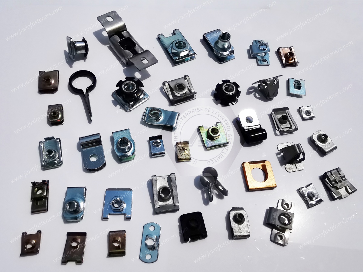
An accurate RFQ should contain the technical information needed to identify the correct clip geometry and commercial configuration.
Product name
Existing supplier part number
2D drawing
3D model, if available
Drawing revision
Application photographs
Assembly location
Metric or inch thread
Nominal thread size
Thread pitch
Thread tolerance
Mating screw type
Screw length
Required thread engagement
Panel thickness
Panel thickness tolerance
Panel material
Edge or hole geometry
Flange dimensions
Clip orientation
Installation direction
Available clearance
Maximum installed height
Maximum installed width
Nut body dimensions
Barrel length
Screw head clearance
Adjacent component clearance
Tool access requirements
Base material
Spring performance requirements
Surface treatment
Corrosion environment
RoHS requirements
REACH requirements
Customer-specific compliance requirements
Static or dynamic loading
Vibration exposure
Temperature variation
Humidity
Chemical exposure
Reuse requirements
Service and maintenance conditions
Prototype quantity
Annual usage
Forecast demand
Target delivery location
Packaging requirements
Inspection requirements
Sample approval requirements
Required documentation
Low-Profile Strong-Grip Clip-On Nuts can provide a compact threaded fastening option for selected sheet-metal, enclosure, automotive and industrial applications.
The correct product selection depends on the relationship between the clip geometry, threaded nut body, panel thickness, available clearance, mating screw and expected service conditions.
JUXIN FASTENERS works with OEM and industrial customers evaluating fastening components for engineering development, prototype sourcing and recurring production requirements.
Our technical review should be based on the customer’s actual drawing, mounting conditions and specification requirements.
The final product configuration, available materials, surface treatment and inspection documentation should be confirmed during the quotation process.
Please send the following information where available:
Product drawing or sample photograph
Thread specification
Panel thickness
Panel material
Maximum clearance requirements
Surface-treatment specification
Application description
Estimated annual demand
Required inspection or compliance documentation
Contact JUXIN FASTENERS
Email: info@juxinfasteners.com
Website: https://www.juxinfasteners.com/
Request a technical quotation for Low-Profile Strong-Grip Clip-On Nuts, sheet-metal clip nuts, barrel clip nuts, enclosed clip nuts or customized OEM fastening components.
Product Packaging
Packaging Standard
At Juxin Fasteners, we apply standardized export packaging to ensure product protection, traceability, and compliance with international logistics requirements.
1. Standard Export Packaging
Unless otherwise specified, all products will be packed according to our factory standard export packaging, which includes:
Moisture-resistant inner protection
Poly bag or small box packing as required
Reinforced export cartons
Clear labeling with part number, specification, batch number, and quantity
Palletizing for sea or air shipment when necessary
Our standard packaging is designed to ensure safe transportation, efficient warehousing, and long-distance international shipping.
2. Customized Packaging Options
We also provide customized packaging solutions according to customer requirements, including but not limited to:
Private labeling
Customized barcodes
Specific carton dimensions
Retail packaging
Special pallet configuration
Customer-specific marking and identification
So that you know, customized packaging may involve additional costs and extended lead time depending on the complexity of the requirements.
3. Compliance & Quality Assurance
All packaging processes are controlled under our ISO 9001 quality management system to ensure consistency, traceability, and product integrity throughout the supply chain.
Product Pictures
Contact Us
Tel.:
+86 020 8621 0320
+86 020 3121 6067
E-mail:
Technical Support:
Navigation
SEND INQUIREY