
Call Us
+86 136 6007 9809
Call Us
+86 136 6007 9809

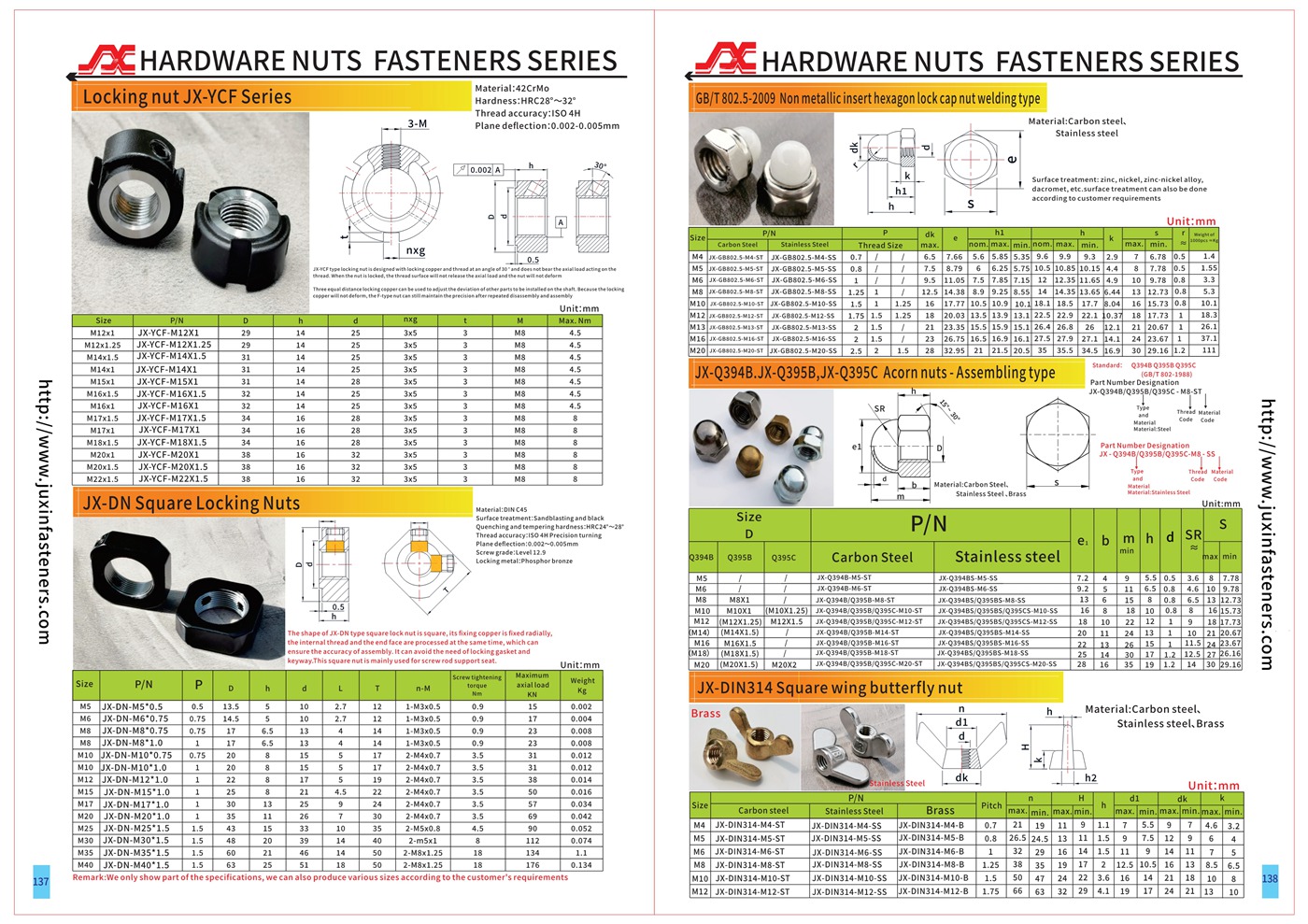
JX-YCF precision bearing lock nuts use a 30° flank-locking mechanism with brass locking elements for accurate shaft retention.
Manufactured from SCM440 (42CrMo4) alloy steel, the series specifies HRC 28–32 hardness and ISO 4H internal threads.
Precision-ground and turned configurations target face runout of 0.002–0.005 mm, subject to size and inspection requirements.
Designed for machine tool spindles, ball screws and precision bearing assemblies. Custom metric and inch-thread drawings are welcome.
Product Specification
JX-YCF Precision Bearing Lock Nuts – 30° Flank-Locking Type
High-Precision SCM440 Shaft Locknuts with Brass Locking Elements for Machine Tool Spindles, Ball Screws and Bearing Retention
JUXIN FASTENERS supplies JX-YCF Series precision bearing lock nuts for high-accuracy mechanical assemblies requiring reliable axial positioning and controlled locking of threaded shafts.
The JX-YCF design belongs to the family of flank-locking precision locknuts. Its locking mechanism uses brass locking elements actuated by screws arranged at approximately 30° to the thread-locking interface.
The mechanism is designed to press the brass elements against the mating shaft threads while minimizing unwanted deformation of the nut's main threaded body.
Unlike ordinary all-metal prevailing-torque nuts, precision flank-locking nuts use a separate mechanical locking arrangement that is tightened after the nut has been positioned on the shaft.
The original JX-YCF specification identifies SCM440 (42CrMo4) alloy steel, HRC 28–32 hardness,
ISO 4H internal thread accuracy and precision face-runout values of 0.002–0.005 mm, depending on the manufacturing and inspection requirements.
Typical applications include machine tool spindles, precision bearing assemblies, ball screw support bearings, rotary axes and industrial motion-control equipment.
Product Technical Specifications
| Parameter | JX-YCF Series Specification |
|---|---|
| Product Name | JX-YCF Precision Bearing Lock Nuts |
| Product Type | Flank-Locking Precision Shaft Locknut |
| Locking Method | Approximately 30° Flank Locking |
| Locking Elements | Brass Thread-Contact Inserts |
| Locking Arrangement | Three-Point Design Described in Original Product Data |
| Nut Body Material | SCM440 Alloy Steel |
| European Material Reference | 42CrMo4, Subject to Material Specification |
| Hardness | HRC 28–32 |
| Internal Thread Accuracy | ISO 4H |
| Precision Ground Configuration | 0.002 mm Face-Runout Reference |
| Precision Turned Configuration | 0.005 mm Face-Runout Reference |
| Surface Finish | Blackened Finish After Surface Preparation |
| Primary Thread System | Metric, Generally Fine Pitch |
| American Thread Options | UNF / UNEF or Drawing-Specific, Subject to Review |
| Custom Manufacturing | According to Approved 2D/3D Drawings |
| Primary Applications | Bearings, Spindles, Ball Screws and Precision Shafts |
Important Specification Qualification
The listed accuracy values describe the supplied technical specification and comparable manufacturing grades.
Final tolerances, inspection methods and acceptance limits must be confirmed for the actual JX-YCF part number.
What Is a Flank-Locking Precision Bearing Nut?
A flank-locking precision bearing nut is a threaded shaft-retention component that uses a dedicated locking mechanism to secure the nut after its axial position has been established.
The nut is first threaded onto the mating shaft.
After the required axial position or bearing adjustment is reached, the locking screws are tightened.
These screws apply force through brass locking elements to the shaft's external thread flanks.
This arrangement provides a controlled locking action without relying on the permanent deformation of the nut's main internal threads.
Engineering Advantages
Controlled shaft-thread locking.
Precision axial positioning.
Potential reduction of damage to mating shaft threads.
Suitable for selected repeated adjustment applications.
Compatibility with precision bearing-retention designs.
High-accuracy machined bearing-contact surfaces.
Customizable thread and dimensional configurations.
Important Engineering Limitation
The locking mechanism does not eliminate the need to verify bearing preload, axial load, screw tightening torque or shaft-thread strength.
30° Flank-Locking Mechanism
The JX-YCF locking concept uses brass contact elements positioned to engage the mating shaft thread flanks.
The original technical description identifies a locking angle of approximately 30° and three distributed locking locations.
Operating Principle
Thread the precision nut onto the mating shaft.
Position the nut against the specified bearing or mechanical component.
Establish the required axial location or bearing preload.
Tighten the locking screws according to the approved procedure.
Allow the brass locking elements to contact the shaft thread flanks.
Verify the final assembly position and locking condition.
Why Brass Locking Elements?
Brass is softer than many hardened steel shaft materials.
A correctly designed brass contact element can conform to the thread flank and distribute locking pressure.
This may help reduce localized thread damage compared with direct steel set-screw contact.
However, thread protection depends on the actual brass element geometry, shaft material, surface hardness and applied locking force.
Why Use a 30° Locking Arrangement?
The angled locking arrangement is intended to direct locking force toward the mating thread flank while limiting undesirable disturbance of the precision nut's axial position.
The effectiveness of this mechanism depends on the actual thread profile, contact geometry and screw arrangement.
Important Distinction
The 30° value refers to the locking geometry, not operating temperature.
Three-Point Locking Design
Three distributed locking locations may provide a more balanced locking arrangement than a single contact point.
For precision shaft applications, the distribution of locking force can influence the final alignment and retention of the assembly.
Critical Design Parameters
Angular spacing of locking positions.
Brass insert geometry.
Locking screw diameter.
Locking screw thread.
Screw tightening torque.
Nut body stiffness.
Shaft-thread accuracy.
Nut-to-shaft thread clearance.
Bearing contact-face geometry.
Engineering Warning
Three-point locking does not automatically guarantee zero movement, zero runout or unlimited vibration resistance.
The complete shaft assembly must be validated.
SCM440 (42CrMo4) Alloy Steel
The JX-YCF nut body is specified as SCM440 alloy steel.
SCM440 is a chromium-molybdenum alloy steel used in mechanical components requiring a combination of strength, toughness and machinability after appropriate heat treatment.
42CrMo4 is a commonly referenced European chromium-molybdenum alloy steel grade.
Important Material Qualification
SCM440 and 42CrMo4 are closely related engineering material designations, but exact chemical composition,
heat-treatment requirements and certification must be checked before claiming complete equivalence.
Specified Hardness: HRC 28–32
The original product data specifies a Rockwell C hardness range of HRC 28–32.
This range should be verified by the approved manufacturing and inspection process.
Engineering Significance
Controlled material hardness can support the mechanical performance and dimensional stability of the precision nut.
However, hardness alone does not establish bearing preload capacity, fatigue resistance or locking torque.
ISO 4H Internal Thread Accuracy
The original specification identifies ISO 4H internal threads.
ISO metric thread tolerance classes define permissible deviations in thread dimensions.
A 4H internal thread tolerance class represents a precision internal-thread requirement.
Important Selection Requirements
Nominal thread diameter.
Thread pitch.
Thread tolerance class.
Mating shaft thread tolerance.
Thread form.
Thread direction.
Functional engagement.
Inspection method.
Engineering Insight
A precision internal thread must be matched with an appropriately specified shaft thread.
A 4H nut thread does not independently guarantee complete assembly accuracy if the mating shaft has excessive pitch error, form error or runout.
Precision Face Runout: 0.002–0.005 mm
Face runout is a critical parameter in precision bearing-retention applications.
It describes the variation of the specified reference face relative to the relevant rotational or thread datum during measurement.
Precision Ground Configuration
The original technical data identifies a face-runout reference of 0.002 mm.
Precision Turned Configuration
The original technical data identifies a face-runout reference of 0.005 mm.
Why Face Runout Matters
Excessive face runout may affect:
Bearing-ring seating.
Axial load distribution.
Bearing preload consistency.
Rotational accuracy.
Spindle vibration.
Assembly repeatability.
Bearing service life.
Important Inspection Requirement
The drawing must identify the datum, measurement method, inspection fixture and acceptance criterion.
Do not assume that a stated 0.002 mm face-runout value applies to every nut diameter or manufacturing configuration.
Precision Grinding vs. Precision Turning
Precision locknuts may be produced using different machining processes.
Precision Grinding
May be selected when tighter control of critical bearing-contact surfaces and runout is required.
Precision Turning
May be suitable where the required tolerances can be achieved through controlled precision machining.
Selection Factors
Required face runout.
Thread accuracy.
Surface finish.
Nut diameter.
Production volume.
Inspection requirements.
Manufacturing cost.
The manufacturing process should be selected according to the actual engineering requirements rather than by assuming that every application requires the tightest available tolerance.
Metric Precision Locknut Thread References
Precision bearing locknuts commonly use metric fine-pitch threads.
The following designations are found in the international precision locknut market and are useful for engineering comparison.
| Metric Thread | Nominal Diameter | Pitch |
|---|---|---|
| M10 × 1.0 | 10 mm | 1.0 mm |
| M12 × 1.0 | 12 mm | 1.0 mm |
| M15 × 1.0 | 15 mm | 1.0 mm |
| M17 × 1.0 | 17 mm | 1.0 mm |
| M20 × 1.0 | 20 mm | 1.0 mm |
| M20 × 1.5 | 20 mm | 1.5 mm |
| M25 × 1.5 | 25 mm | 1.5 mm |
| M30 × 1.5 | 30 mm | 1.5 mm |
| M35 × 1.5 | 35 mm | 1.5 mm |
| M40 × 1.5 | 40 mm | 1.5 mm |
| M45 × 1.5 | 45 mm | 1.5 mm |
| M50 × 1.5 | 50 mm | 1.5 mm |
| M55 × 2.0 | 55 mm | 2.0 mm |
| M60 × 2.0 | 60 mm | 2.0 mm |
| M70 × 2.0 | 70 mm | 2.0 mm |
| M80 × 2.0 | 80 mm | 2.0 mm |
| M100 × 2.0 | 100 mm | 2.0 mm |
Availability Notice
These are market reference thread sizes, not a confirmed JX-YCF production range.
The original JX-YCF data does not provide a complete model-by-model dimensional table.
Actual thread sizes, outside diameters, nut heights, locking screw arrangements and manufacturing availability must be confirmed against the JUXIN FASTENERS drawing or catalog.
American Inch-Series Precision Locknut Requirements
American industrial customers may specify precision shaft locknuts using inch-based Unified threads.
Unlike general-purpose hex nuts, precision bearing locknuts often use fine or extra-fine threads because axial adjustment resolution and shaft geometry are important.
Potential thread systems include:
UNF – Unified National Fine.
UNEF – Unified National Extra Fine.
UNS – Unified Special Thread Series, Where Applicable.
Common Inch Thread References
| Thread Designation | Nominal Diameter | Threads per Inch |
|---|---|---|
| 1/4"-28 UNF | 0.250 in | 28 |
| 5/16"-24 UNF | 0.3125 in | 24 |
| 3/8"-24 UNF | 0.375 in | 24 |
| 7/16"-20 UNF | 0.4375 in | 20 |
| 1/2"-20 UNF | 0.500 in | 20 |
| 1/2"-28 UNEF | 0.500 in | 28 |
| 5/8"-18 UNF | 0.625 in | 18 |
| 5/8"-24 UNEF | 0.625 in | 24 |
| 3/4"-16 UNF | 0.750 in | 16 |
| 3/4"-20 UNEF | 0.750 in | 20 |
| 7/8"-14 UNF | 0.875 in | 14 |
| 7/8"-20 UNEF | 0.875 in | 20 |
| 1"-12 UNF | 1.000 in | 12 |
| 1"-20 UNEF | 1.000 in | 20 |
Important American Market Qualification
These are thread-system references for customer-specific engineering review.
They are not confirmation that the JX-YCF Series is currently manufactured in every listed inch size.
A custom inch-thread precision locknut requires confirmation of the shaft thread, bearing contact geometry, locking mechanism and inspection tolerances.
Metric and Inch Threads Are Not Interchangeable
Metric fine-pitch threads cannot be substituted with UNF or UNEF threads based only on nominal diameter similarity.
For example:
M20 × 1.0 is not interchangeable with 3/4"-20 UNEF.
M25 × 1.5 is not interchangeable with 1"-12 UNF.
M12 × 1.0 is not interchangeable with 1/2"-20 UNF.
The complete thread specification must match the mating shaft.
JX-YCF vs. Conventional Bearing Locknuts
Conventional bearing locknuts may use a tab washer, keyway or other locking arrangement.
The JX-YCF Series uses a separate screw-actuated brass-contact locking mechanism.
| Feature | JX-YCF Precision Locknut | Conventional Tab-Washer Locknut |
|---|---|---|
| Locking Principle | Brass Elements Acting on Thread Flanks | Mechanical Tab Engagement |
| Locking Adjustment | Screw-Actuated | Washer and Nut Arrangement |
| Shaft Keyway | Not Inherently Required by Flank-Locking Concept | Required for Some Washer Systems |
| Precision Face Control | According to Precision Drawing | Depends on Product Standard |
| Repeated Adjustment | Possible Within Approved Limits | Depends on Washer and Nut Condition |
| Application | Precision Shaft and Bearing Assemblies | General and Bearing Retention Applications |
Important Engineering Qualification
The JX-YCF design should not automatically be considered interchangeable with DIN 981-style bearing locknuts or other locking systems.
Dimensions, bearing-contact surfaces, thread specifications and axial load requirements must be verified.
JX-YCF vs. Ordinary All-Metal Self-Locking Nuts
Ordinary all-metal prevailing-torque nuts often use deliberate thread deformation or other interference features.
JX-YCF precision locknuts instead use separate brass locking elements actuated by screws.
Key Differences
JX-YCF is designed for precision shaft positioning.
Locking occurs after the nut is positioned.
The brass elements act against the mating shaft thread flanks.
The locking system requires a defined screw-tightening procedure.
Precision face runout and bearing contact geometry are critical.
These differences make the JX-YCF Series a specialized precision component rather than a general-purpose replacement for distorted-thread hex locknuts.
Bearing Preload and Axial Positioning
Precision bearing assemblies may require controlled axial positioning or preload.
A precision locknut can be part of the mechanism used to establish and retain the required position.
Engineering Considerations
Bearing type.
Bearing arrangement.
Shaft stiffness.
Required preload.
Thermal expansion.
Nut contact-face runout.
Mating shaft accuracy.
Locking screw torque.
Operating speed.
Service temperature.
Critical Warning
The locking screws should not be used as a substitute for the approved bearing preload adjustment procedure.
Excessive preload can increase bearing temperature, friction and premature wear.
Insufficient preload may contribute to unwanted axial movement or reduced rotational accuracy.
Industrial Applications and Engineering Solutions
1. CNC Machine Tool Spindles
CNC spindles require accurate bearing positioning and stable rotational performance.
Engineering Challenge
Face runout, preload variation and shaft-thread accuracy may influence spindle vibration and machining quality.
Potential Solution
JX-YCF precision locknuts may be specified for compatible spindle bearing arrangements.
2. Ball Screw Support Bearings
Ball screw systems use precision bearings to support axial and rotational loads.
Engineering Challenge
Incorrect axial positioning may affect backlash, positioning repeatability and bearing performance.
Potential Solution
A precision flank-locking nut may retain the approved bearing position on a threaded support shaft.
3. High-Speed Machining Centers
High-speed machinery places demanding requirements on bearing accuracy and thermal stability.
Potential Solution
Precision-ground locknuts may be evaluated where the required face-runout tolerance is supported by inspection.
4. Industrial Robotics
Robotic joints and motion-control mechanisms require repeatable positioning.
Potential Solution
Precision shaft locknuts may be used in suitable rotary-axis bearing assemblies.
5. Semiconductor Manufacturing Equipment
Semiconductor equipment often contains high-precision motion stages and rotary mechanisms.
Engineering Challenge
Dimensional stability, cleanliness and repeatable mechanical positioning may be critical.
Potential Solution
JX-YCF locknuts may be evaluated for approved precision motion assemblies, subject to cleanliness and material requirements.
6. Precision Grinding Machines
Grinding machine spindles require controlled bearing positioning and low rotational error.
Potential Solution
Precision bearing locknuts may support the required axial retention and assembly adjustment.
7. Industrial Automation
Automated machinery uses rotary shafts, bearings and motion-control systems.
Potential Solution
Flank-locking precision nuts may be specified for compatible bearing-support assemblies.
8. Printing and Packaging Machinery
High-speed rollers and rotating assemblies may require accurate shaft retention.
Potential Solution
Precision locknuts can be considered where axial positioning and repeated maintenance adjustments are important.
9. Precision Inspection Equipment
Metrology and inspection machines may contain accurately positioned rotating components.
Potential Solution
High-accuracy locknuts may be used where the mechanical design requires controlled face runout and axial location.
10. Electric Motor Test Equipment
Motor test benches and dynamometer systems include rotating shafts and bearing supports.
Potential Solution
Precision shaft locknuts may be selected for appropriate test equipment bearing arrangements.
11. Industrial Gearboxes
Gearbox assemblies may require axial retention of bearings and rotating components.
Potential Solution
Precision locknuts may be evaluated where shaft geometry and locking requirements permit their use.
12. Rotary Tables and Indexing Systems
Rotary positioning equipment depends on accurate bearing location.
Potential Solution
Precision flank-locking nuts may support the designed axial retention system.
13. Precision Linear Motion Systems
Some linear motion systems use ball screw assemblies and support bearings.
Potential Solution
JX-YCF locknuts may be considered for compatible ball screw bearing-support arrangements.
14. Medical Equipment Manufacturing Machinery
Manufacturing equipment used to produce medical devices may require high-accuracy motion components.
Potential Solution
Precision bearing locknuts may be evaluated for appropriate production machinery, subject to equipment specifications.
15. Aerospace Manufacturing Equipment
Aerospace manufacturing fixtures and machine tools may require high-precision rotating systems.
Potential Solution
Precision shaft locknuts may be specified for suitable manufacturing equipment, not as automatically approved flight hardware.
16. EV Motor Manufacturing Equipment
Electric motor production lines use precision rotating and positioning machinery.
Potential Solution
JX-YCF locknuts may support approved bearing-retention applications within manufacturing equipment.
17. Optical Manufacturing Machinery
Optical production equipment often requires controlled motion and low mechanical runout.
Potential Solution
Precision locknuts may be considered for compatible rotary components.
18. OEM Precision Mechanical Assemblies
Equipment manufacturers may require customized locknut geometry, thread specifications and inspection requirements.
Potential Solution
JUXIN FASTENERS can review custom precision locknut drawings for manufacturing feasibility.
Installation and Assembly Procedure
The exact installation procedure must follow the approved equipment and nut specifications.
Step 1 – Inspect the Components
Check the nut, locking screws, brass locking elements and mating shaft threads.
Step 2 – Clean the Contact Surfaces
Remove contamination that could affect seating, thread fit or inspection.
Step 3 – Verify Thread Compatibility
Confirm nominal diameter, pitch, thread direction and tolerance class.
Step 4 – Position the Nut
Thread the nut onto the shaft and bring it into contact with the intended bearing or mechanical component.
Step 5 – Establish Axial Position or Preload
Follow the bearing manufacturer's approved procedure.
Step 6 – Tighten the Locking Screws
Apply the specified locking screw torque and tightening sequence.
Step 7 – Verify the Assembly
Check axial position, runout, preload and locking condition as required.
Step 8 – Document Inspection Results
Record the relevant measurements for production or maintenance traceability.
Important Installation Warning
Do not invent a universal tightening torque for the JX-YCF Series.
Locking screw torque depends on nut size, screw diameter, thread geometry and the approved design.
Reuse and Maintenance
The brass-contact locking mechanism may permit repeated adjustment or removal when handled correctly.
However, repeated use should not be interpreted as unlimited reuse.
Inspection Before Reassembly
Brass locking element wear.
Locking screw damage.
Internal thread condition.
Mating shaft thread damage.
Nut face condition.
Corrosion.
Surface contamination.
Dimensional or runout changes.
Replace components that no longer meet the approved requirements.
Blackened Surface Finish
The original JX-YCF data describes a blackened finish following sandblasting or surface preparation.
Important Technical Distinction
Sandblasting is a surface preparation process, while blackening is a separate finishing treatment.
The exact blackening method, coating thickness and corrosion resistance must be specified if required.
Engineering Considerations
Surface appearance.
Corrosion protection.
Surface cleanliness.
Dimensional influence.
Bearing-contact surface condition.
Storage and handling requirements.
A blackened finish should not be assumed to provide substantial corrosion protection in wet or chemically aggressive environments without a verified coating specification.
Precision Manufacturing and Inspection
Material Inspection
SCM440 material grade.
Chemical composition.
Heat-treatment records.
Material traceability.
Hardness Inspection
HRC 28–32 requirement.
Approved measurement location.
Test method.
Production-lot acceptance.
Thread Inspection
Nominal diameter.
Thread pitch.
ISO 4H tolerance.
Thread form.
Thread direction.
Functional fit.
Geometric Inspection
Outside diameter.
Nut height.
Bearing-contact face.
Face runout.
Concentricity, where specified.
Parallelism, where specified.
Locking hole position.
Locking Mechanism Inspection
Brass insert geometry.
Locking screw dimensions.
Locking screw engagement.
Locking torque.
Locking element movement.
Repeated assembly performance, where required.
Surface Inspection
Blackened finish.
Surface damage.
Burrs.
Corrosion.
Cleanliness.
Engineering Note
Runout, concentricity and parallelism are separate geometric characteristics. They must not be treated as interchangeable inspection terms.
Common Engineering Problems and Solutions
Problem 1: Excessive Bearing Face Runout
Possible Causes
Incorrect nut face geometry.
Damaged contact surface.
Mating shaft error.
Contamination during assembly.
Recommended Action
Verify the nut, shaft and assembled bearing-contact geometry using the approved measurement method.
Problem 2: Bearing Preload Changes After Locking
Possible Causes
Uneven locking screw tightening.
Incorrect assembly sequence.
Inadequate shaft-thread accuracy.
Uncontrolled bearing adjustment.
Recommended Action
Review the locking sequence and measure the final bearing condition.
Problem 3: Damage to Shaft Threads
Possible Causes
Excessive locking screw torque.
Damaged brass locking elements.
Incorrect thread fit.
Contaminated components.
Recommended Action
Inspect the locking mechanism and follow the approved tightening procedure.
Problem 4: Nut Loosens During Operation
Possible Causes
Insufficient locking force.
Incorrect screw torque.
Worn locking elements.
Unverified vibration conditions.
Recommended Action
Validate locking torque, component condition and the complete operating environment.
Problem 5: Incorrect Thread Pitch
Possible Causes
Similar-looking metric fine threads.
Incorrect shaft drawing.
Wrong part number.
Inch-to-metric substitution.
Recommended Action
Confirm the exact nominal thread and pitch before installation.
Problem 6: Excessive Spindle Vibration
Possible Causes
Bearing preload error.
Shaft runout.
Nut face runout.
Bearing damage.
Rotor imbalance.
Recommended Action
Evaluate the complete spindle system rather than assuming the nut is the only cause.
Problem 7: Locking Screw Damage
Possible Causes
Incorrect tool.
Excessive torque.
Thread contamination.
Repeated misuse.
Recommended Action
Inspect the screws and replace damaged components.
Problem 8: Incorrect Precision Grade
Possible Causes
Assuming all products achieve 0.002 mm runout.
Using a turning-grade product where a grinding-grade tolerance is required.
Recommended Action
Specify the required runout and inspection acceptance criteria on the drawing.
Problem 9: Incorrect Surface Finish
Possible Causes
Unspecified blackening process.
Corrosion environment not considered.
Recommended Action
Confirm the surface treatment and environmental requirements.
Problem 10: Dimensional Interference
Possible Causes
Incorrect outside diameter.
Incorrect nut height.
Insufficient tool clearance.
Incompatible locking screw access.
Recommended Action
Review the complete 2D/3D assembly before procurement.
OEM Engineering Selection Checklist
Before selecting a JX-YCF precision locknut, confirm:
Shaft nominal diameter.
Thread pitch.
Thread direction.
Internal thread tolerance.
Shaft thread tolerance.
Nut outside diameter.
Nut height.
Bearing-contact face dimensions.
Required face runout.
Required parallelism.
Required concentricity.
Shaft material and hardness.
Nut material and hardness.
Brass locking element design.
Locking screw size.
Locking screw torque.
Bearing type.
Bearing preload.
Axial load.
Rotational speed.
Operating temperature.
Vibration environment.
Surface finish.
Inspection documentation.
Estimated annual purchasing volume.
Custom JX-YCF Precision Locknuts for OEM Manufacturing
JUXIN FASTENERS supports customer-specific precision locknut inquiries.
Potential custom requirements include:
SCM440 / 42CrMo4 alloy steel.
Custom metric fine threads.
Customer-specific inch threads.
ISO 4H internal threads.
Precision-ground bearing-contact faces.
Precision-turned configurations.
Custom outside diameters.
Custom nut heights.
Three-point brass flank locking.
Custom locking screw dimensions.
Specified hardness.
Blackened surface finishes.
Drawing-defined runout tolerances.
Dimensional inspection reports.
Material certification.
Bulk OEM production.
All custom specifications require technical review and manufacturing feasibility confirmation.
Frequently Asked Engineering and Procurement Questions
What is a JX-YCF precision locknut?
It is a precision shaft locknut using a screw-actuated brass flank-locking mechanism.
What is the American name for this product?
Precision Bearing Lock Nut, Flank-Locking Precision Locknut and Precision Shaft Locknut are relevant American industrial terms.
What does F-type mean?
In precision locknut terminology, F-type is commonly associated with flank-locking arrangements.
Exact designations vary by manufacturer.
What does 30° locking mean?
It refers to the locking mechanism geometry used to direct force toward the shaft thread flanks.
Why are brass locking elements used?
They provide a relatively soft contact interface between the locking screws and mating shaft threads.
What material is specified?
SCM440 chromium-molybdenum alloy steel, with 42CrMo4 as a relevant European material reference.
What hardness is specified?
HRC 28–32.
What is ISO 4H?
A precision tolerance class for metric internal threads.
What is the face-runout specification?
The original technical data identifies 0.002 mm and 0.005 mm references for different precision manufacturing configurations.
Are all JX-YCF sizes guaranteed to achieve 0.002 mm?
No. The tolerance must be confirmed for the actual part number, manufacturing process and inspection requirement.
Can these locknuts be used on ball screws?
They may be suitable for compatible ball screw support-bearing assemblies.
Can they be used on machine tool spindles?
Yes, where the approved spindle design requires this type of precision locking arrangement.
Do they require a tab washer?
The flank-locking mechanism is designed to provide locking through its brass elements and screws.
The final assembly requirements depend on the engineering design.
Can the nut be reused?
Potentially, after inspection and within the approved reuse requirements.
Are inch-thread versions available?
Customer-specific UNF, UNEF or other inch-thread requirements may be reviewed against engineering drawings.
Can metric and inch threads be interchanged?
No.
Can JUXIN FASTENERS manufacture custom sizes?
Customer drawings can be reviewed for manufacturing feasibility.
Can OEM customers request production quantities?
Yes. JUXIN FASTENERS welcomes bulk OEM and long-term supply inquiries.
Related Industrial Fastening and Precision Components
JUXIN FASTENERS offers related components for industrial equipment manufacturing:
All-Metal Self-Locking Nuts.
Precision Locking Nuts.
Industrial Hex Nuts.
Specialty Lock Nuts.
Custom CNC Machining Parts.
Thread Repair Inserts.
Weld Fasteners.
Self-Clinching Fasteners.
Custom Threaded Components.
Internal links should point only to verified live pages.
Request a JX-YCF Precision Locknut OEM RFQ
JUXIN FASTENERS supports international OEM manufacturers, machine tool builders, precision equipment manufacturers, mechanical design engineers, production managers, purchasing engineers and global supply chain teams.
For an accurate quotation, please provide:
JX-YCF model or reference number.
2D engineering drawing.
3D CAD model, if available.
Application and equipment type.
Shaft nominal diameter.
Metric or inch thread designation.
Thread pitch and direction.
Thread tolerance.
Nut outside diameter.
Nut height.
Bearing-contact face dimensions.
Required face runout.
Required parallelism and concentricity.
Material grade.
Hardness requirement.
Locking mechanism details.
Locking screw dimensions.
Required locking torque.
Surface finish.
Inspection and certification requirements.
Initial order quantity.
Estimated annual purchasing volume.
Packaging requirements.
Delivery schedule.
Our technical sales team can review your requirements for dimensional accuracy, material selection, manufacturing feasibility, quality inspection and OEM quotation.
JUXIN FASTENERS
Website: https://www.juxinfasteners.com/
Email: info@juxinfasteners.com
Submit Your Precision Locknut Drawings and Bulk Purchasing Requirements for an OEM RFQ.
Product Packaging
Packaging Standard
At Juxin Fasteners, we apply standardized export packaging to ensure product protection, traceability, and compliance with international logistics requirements.
1. Standard Export Packaging
Unless otherwise specified, all products will be packed according to our factory standard export packaging, which includes:
Moisture-resistant inner protection
Poly bag or small box packing as required
Reinforced export cartons
Clear labeling with part number, specification, batch number, and quantity
Palletizing for sea or air shipment when necessary
Our standard packaging is designed to ensure safe transportation, efficient warehousing, and long-distance international shipping.
2. Customized Packaging Options
We also provide customized packaging solutions according to customer requirements, including but not limited to:
Private labeling
Customized barcodes
Specific carton dimensions
Retail packaging
Special pallet configuration
Customer-specific marking and identification
So that you know, customized packaging may involve additional costs and extended lead time depending on the complexity of the requirements.
3. Compliance & Quality Assurance
All packaging processes are controlled under our ISO 9001 quality management system to ensure consistency, traceability, and product integrity throughout the supply chain.
Product Pictures

Contact Us
Tel.:
+86 020 8621 0320
+86 020 3121 6067
E-mail:
Technical Support:
Navigation
SEND INQUIREY


