Call Us
+86 136 6007 9809
Call Us
+86 136 6007 9809

Keyhole standoffs and keyhole fasteners offer another mounting architecture.
Product Specification
In modular equipment, the challenge is often not simply how to fasten two components together.
The harder question is:
How can a technician position, temporarily support, align, secure and later remove a panel or module without managing several loose fasteners at the same time?
Traditional threaded mounting can work well, but each attachment point may require alignment between a screw, clearance hole and female thread.
During assembly or maintenance, the operator may also need to support the component while starting the first fasteners.
Keyhole standoffs and keyhole fasteners offer another mounting architecture.
A shaped standoff head passes through the enlarged entry portion of a mating keyhole slot.
The component then moves into a narrower retention section, where the geometry beneath the head engages the mating panel.
Depending on the complete design, the mounted component can then be secured against reverse movement using a screw, captive fastener, latch, stop, spring feature or another locking method.
This architecture can support faster positioning, reduced loose-hardware handling and easier service access in AI server equipment,
electrical cabinets, network infrastructure, industrial automation, semiconductor equipment, power electronics and other modular sheet-metal systems.
But keyhole mounting should not be reduced to the phrase “tool-less fastener.”
The engineering performance comes from the relationship between:
Standoff Geometry + Keyhole Slot Geometry + Mating Panel Thickness + Direction of Assembly + Load Path + Final Retention Method
That complete relationship determines whether the assembly slides smoothly, retains correctly and remains secure in service.
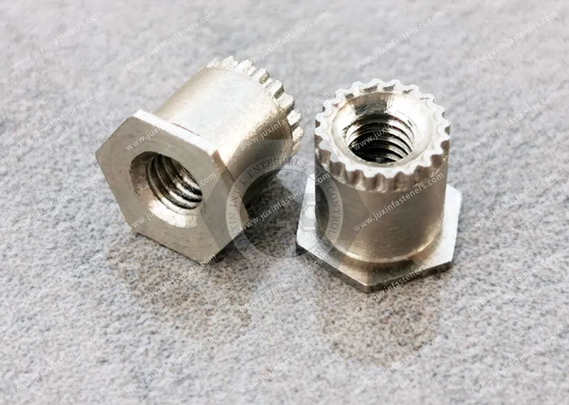
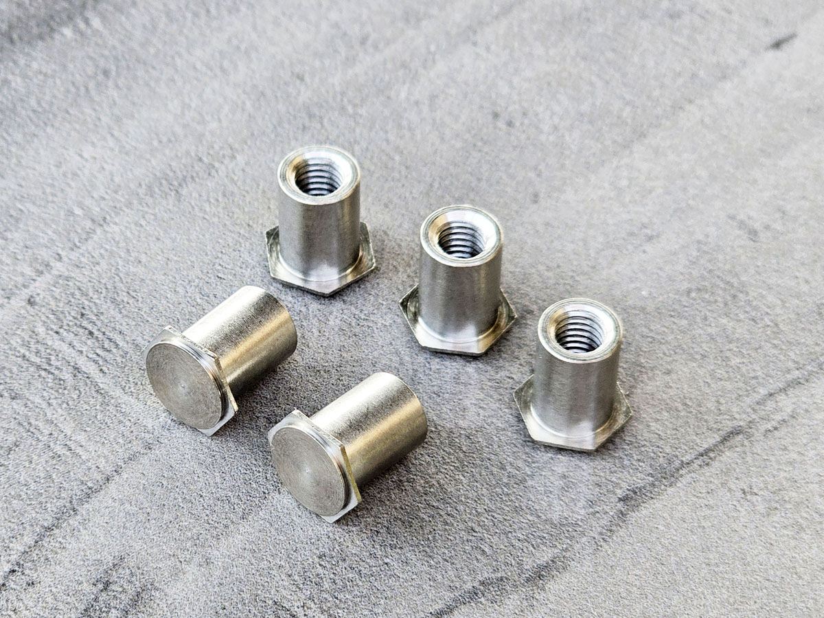
A keyhole standoff is a mounting fastener with a head and neck geometry designed to engage a corresponding keyhole-shaped opening in another component.
Depending on the specific design, the standoff may be permanently attached to a host panel by a self-clinching, press-in or other engineered attachment method.
The mating component contains a keyhole slot with two functional regions:
a larger entry opening that allows the standoff head to pass through; and
a narrower retention slot that captures the neck beneath the head after relative movement.
The basic assembly sequence is:
Align Entry Opening → Insert Standoff Head → Translate Component → Engage Retention Slot → Apply Final Retention if Required
This makes the keyhole standoff fundamentally different from a conventional threaded standoff.
A threaded standoff normally relies on screw engagement for attachment.
A keyhole standoff relies first on geometric capture and relative movement.
This is one of the most important engineering principles for keyhole hardware.
The standoff cannot be evaluated independently from the mating keyhole slot.
A perfectly manufactured standoff can still produce:
difficult insertion;
binding;
excessive looseness;
rattling;
incomplete engagement;
accidental disengagement;
poor alignment;
or inconsistent assembly
if the mating slot geometry is wrong.
Therefore, keyhole hardware should be treated as a two-component interface:
Keyhole Standoff Geometry ↔ Mating Keyhole Slot Geometry
For OEM sourcing, the mating slot drawing can be just as important as the fastener drawing.
The mounting process normally includes several distinct stages.
The larger portion of the keyhole slot must allow the intended standoff head to enter.
This requires sufficient clearance for:
head diameter or head envelope;
manufacturing variation;
panel positioning;
coating where relevant;
and the intended assembly angle.
After entry, the mating component moves relative to the standoff.
This movement transfers the neck into the narrower slot.
The required travel depends on the slot design.
Once the neck reaches the retention region, the larger head overlaps the mating panel around the slot.
The geometry can then resist separation in the direction normal to the mating panel within the limits of the actual design.
The component reaches its intended mounted position.
Stops, locating features or other geometry may establish this position.
Where reverse sliding could cause disengagement, the assembly requires an appropriate method of preventing unintended movement back toward the entry opening.
This may involve:
a screw;
captive screw;
latch;
spring feature;
stop;
secondary fastener;
geometric constraint;
or another engineered retention method.
The keyhole feature should not automatically be assumed to provide every direction of final restraint.
Both architectures can support or space components, but they solve different assembly problems.
A conventional threaded standoff may be preferable when:
positive threaded attachment is required at each mounting point;
relative sliding during assembly is undesirable;
screw torque is part of the defined joint;
repeated screw installation is acceptable;
and the component can be supported during fastening.
A keyhole standoff may be preferable when:
a module should first be positioned or supported before final securing;
several mounting points need to engage simultaneously;
loose fastener handling should be reduced;
rapid module installation or removal is valuable;
access to individual screws is difficult;
or a slide-fit mounting sequence suits the equipment architecture.
The keyhole standoff is therefore not simply a “faster threaded standoff.”
It changes the assembly sequence.
These products can both improve serviceability, but they work differently.
A captive panel screw keeps a threaded screw retained with the removable panel so the screw does not separate from the assembly during service.
A keyhole standoff creates a geometric hang-and-slide or insert-and-translate interface.
In some equipment, the two architectures can work together:
Keyhole Standoffs → Position and Temporarily Support the Module
Captive Screw → Provide Final Retention
This can reduce loose hardware while still providing a positive final fastening step.
The appropriate combination depends on the actual equipment design.
The keyhole slot normally includes several important dimensions:
entry-opening size;
retention-slot width;
slot length;
transition geometry;
end geometry;
mating-panel thickness;
and positional relationship to other mounting features.
The standoff includes corresponding dimensions such as:
head diameter or head envelope;
neck diameter;
under-head gap;
body diameter;
standoff height;
mounting geometry;
and overall installed envelope.
These dimensions must be evaluated together.
The enlarged entry opening must allow the standoff head to pass through during assembly.
Conceptually:
Entry Opening > Required Standoff Head Envelope
But this should not be converted into a universal clearance number.
The required allowance depends on:
manufacturing tolerances;
coating;
alignment;
assembly angle;
module size;
number of simultaneous keyhole engagement points;
and required ease of installation.
A large module engaging several keyhole standoffs simultaneously may require different tolerance treatment from a small cover using only a few mounting points.
The narrow section of the keyhole slot must accept the standoff neck while remaining sufficiently narrow for the head to overlap the mating material.
Conceptually:
Retention Slot Width > Neck Envelope
while
Retention Slot Width < Retaining Head Envelope
However, the actual dimensions and tolerances must come from the specific design.
Too little clearance can cause:
binding;
difficult installation;
sensitivity to coating;
sensitivity to hole-position variation;
and inconsistent field service.
Too much clearance can contribute to:
lateral movement;
rattle;
inconsistent module position;
and impact loading during vibration or transport.
The correct objective is not the smallest possible clearance.
It is controlled clearance appropriate to assembly and service requirements.
The axial space beneath the retaining head must accommodate the mating component.
That relationship can include:
Mating Panel Thickness + Surface Finish + Required Sliding Clearance + Manufacturing Variation
If the available gap is too small, the component may bind.
If it is unnecessarily large, the mounted component may have excessive movement normal to the panel.
This is why procurement teams should not cross-reference keyhole standoffs using only head diameter and overall height.
The neck gap / under-head gap may be a critical functional dimension.
The component must move far enough after insertion for the standoff head to reach the intended retained position.
Required travel influences:
service access;
cable slack;
neighboring component clearance;
module insertion path;
technician movement;
end-stop design;
and final locking location.
This becomes particularly important in dense server, network, semiconductor and electrical equipment.
A keyhole system that works geometrically on a CAD screen may still be difficult to service if the real equipment does not provide sufficient travel space.
Keyhole mounting is often illustrated vertically, with gravity helping a panel settle into the retained position.
Real equipment may be mounted:
vertically;
horizontally;
overhead;
on a moving machine;
inside a vehicle;
inside a rail system;
or in equipment exposed to shock and vibration.
The direction of gravity and service loads therefore matters.
If gravity naturally drives the module toward the retained end of the slot, the assembly behaves differently from one where gravity encourages reverse movement toward the entry opening.
This leads to an important design question:
What prevents the module from moving back toward the release position during actual service conditions?
The keyhole geometry may temporarily retain or support the component during assembly.
That does not automatically mean the joint is fully secured for operation.
Depending on the application, final retention may be provided by:
captive screw;
conventional screw;
latch;
locking pin;
spring feature;
stop;
bracket;
cover geometry;
or another mechanism.
The number and type of final locking features should come from the assembly's actual load and safety requirements.
There is no universal rule that “one locking screw” is sufficient.
Keyhole engagement itself may not require a tool.
The complete assembly may still require tools for:
final locking;
safety retention;
electrical bonding;
access control;
torque-controlled joints;
or removal of adjacent components.
For that reason, quick-mount, slide-fit, hang-and-slide or reduced loose-hardware mounting may be more technically accurate descriptions than universally calling the system tool-less.
Another important distinction is between:
supporting a component during assembly
and
carrying the full operating load of the equipment.
A keyhole standoff may help hold a module while the technician installs the final retaining hardware.
That does not automatically establish that the standoffs alone should carry:
full static load;
shock load;
vibration load;
transportation load;
crash load;
or safety-critical structural load.
The complete load path must be evaluated.
Potential load paths can include:
Module → Keyhole Slot Edge → Standoff Neck / Head → Standoff Body → Host Panel
and, after final fastening:
Module → Final Fastener / Clamped Interface → Supporting Structure
The proportion carried by each path depends on the design.
Engineers should therefore evaluate:
module mass;
center of gravity;
number of mounting points;
load direction;
slot-edge stress;
panel thickness;
local panel deformation;
standoff geometry;
host-panel retention;
final locking mechanism;
vibration;
shock;
and service loads.
There is no universal keyhole-standoff load rating that can be transferred from one geometry to another.
One keyhole feature may be easy to engage.
Four, six or more keyhole standoffs engaging simultaneously create a different engineering challenge.
The assembly now depends on the relative position of:
every installed standoff;
every keyhole slot;
host-panel dimensions;
mating-panel dimensions;
bends;
hole patterns;
coatings;
and assembly datums.
If every engagement point is designed with almost zero clearance, tolerance accumulation may cause binding.
If every point has excessive clearance, the assembly may move or rattle.
A better approach is to determine:
which features locate the module;
which features provide clearance;
which features support load;
and which feature locks the final position.
This separation of functions can make the assembly more tolerant and predictable.
The body height of a keyhole standoff can contribute to spacing between components.
But the final assembly spacing can also depend on:
host-panel thickness;
mating-panel position;
head geometry;
formed features;
washers or other interfaces;
coating;
panel flatness;
and tolerance stack-up.
Therefore, specifying a standoff body height alone does not guarantee a final board-to-board or panel-to-panel distance.
The complete assembly stack should be evaluated.
Keyhole hardware is especially relevant where equipment contains removable modules, internal sub-panels or service assemblies that benefit from positioning before final fastening.
AI computing systems, GPU servers, network switches, storage equipment and rack-mounted power infrastructure use increasingly dense modular mechanical architectures.
Potential keyhole-standoff applications may include suitable:
internal sub-chassis;
removable power assemblies;
fan or cooling-control trays;
cable-management structures;
service panels;
rack-mounted electronics;
network equipment modules;
PDU internal assemblies;
UPS control structures;
and equipment brackets.
The primary benefit is not simply “faster server screws.”
Keyhole hardware can change the installation sequence by allowing a module to engage fixed mounting points before final retention.
In dense rack equipment, this may reduce the need to simultaneously hold a component and align several separate screws.
Actual load capacity, service direction and final retention must still be validated for the equipment.
Cooling Distribution Units, liquid-cooling control cabinets and related thermal-management equipment contain pumps, controls, sensors, electrical components, manifolds and serviceable modules.
Keyhole standoffs may be considered for suitable:
control sub-panels;
electrical modules;
service covers;
cable-management structures;
sensor assemblies;
and removable internal brackets.
The benefit can be easier positioning and service access.
Keyhole mounting should not be assumed suitable for fluid-pressure boundaries or as the sole retention method for pressurized cooling components.
Electrical cabinets frequently contain removable:
mounting plates;
controller assemblies;
inverter modules;
power-electronics subassemblies;
internal shields;
interface panels;
and service covers.
A keyhole interface can allow the component to be placed on fixed standoffs before final locking.
This can be useful when rear access for loose nuts is limited.
However, keyhole hardware does not automatically establish electrical grounding or bonding.
Where electrical continuity is required, the complete contact interface, material, finish and assembly must be evaluated.
Communication equipment often uses modular internal structures to simplify installation and field service.
Potential applications include:
network equipment chassis;
communication cabinets;
base-station-associated equipment;
antenna electronics;
fiber equipment;
power modules;
internal mounting plates;
and outdoor equipment enclosures.
Keyhole standoffs may allow a technician to position a sub-panel before connecting wiring or applying final retention.
Outdoor equipment still requires separate evaluation of corrosion, environmental sealing and vibration.
Industrial equipment often combines large frames with modular controls, guards, electronics and serviceable subassemblies.
Potential applications include:
robot control cabinets;
machine-control panels;
automation modules;
vision-system enclosures;
inspection equipment;
packaging machinery;
conveyor controls;
and removable machine panels.
Keyhole hardware can simplify positioning during assembly and maintenance.
For moving machinery, however, dynamic loading and unintended reverse sliding must be considered carefully.
Automation systems frequently require modular I/O assemblies, control panels and electrical subassemblies that may be installed late in the equipment build.
A slide-fit architecture can allow a mounting plate to engage preinstalled standoffs before electrical connections and final retention are completed.
This can improve assembly sequencing where access becomes restricted after neighboring equipment is installed.
The benefit depends on the actual cabinet and module design.
Semiconductor manufacturing equipment combines precision mechanical structures, automation, electronics, controls and service modules.
Potential keyhole applications may include suitable:
electronics enclosures;
control modules;
service panels;
cable-management structures;
internal mounting plates;
and equipment subassemblies.
Quick positioning may simplify maintenance in densely packaged equipment.
A generic keyhole fastener should not be described as vacuum-compatible, cleanroom-qualified or semiconductor-process compatible unless specifically validated.
Automotive equipment uses modular electronics and serviceable assemblies throughout the vehicle and manufacturing environment.
Potential keyhole applications may include suitable:
electronics mounting structures;
control modules;
charging equipment;
service brackets;
interior equipment;
vehicle production equipment;
and diagnostic or assembly fixtures.
The architecture may reduce loose hardware during module positioning.
For vehicle-mounted applications, shock, vibration, crash loads and final retention requirements must be separately evaluated.
Keyhole engagement alone should not be described as automotive vibration-proof.
Battery and energy-storage equipment contains control systems, BMS electronics, power distribution, thermal-management controls and service modules.
Keyhole standoffs may be useful for appropriate:
electronics sub-panels;
internal control assemblies;
serviceable brackets;
secondary covers;
and cabinet modules.
They should not automatically be positioned as structural battery-module restraints or enclosure-sealing fasteners.
Those functions require separate joint design and validation.
Rail equipment contains electrical, communication and control modules that require service access over long equipment life.
Potential keyhole applications may include:
equipment cabinets;
electronics panels;
communication assemblies;
interior control equipment;
and maintenance-access structures.
The architecture can assist positioning and service.
Rail vibration, shock, fire and program qualification requirements remain separate from the fastener's basic geometry.
HVAC equipment contains electrical controls, power electronics, sensors and serviceable internal modules.
Potential applications include:
control sub-panels;
electronics assemblies;
internal brackets;
equipment covers;
and service modules.
Keyhole hardware can support a hang-and-position assembly sequence.
It does not automatically provide airtight or waterproof attachment.
Suitable applications may include:
diagnostic equipment;
laboratory instruments;
medical carts;
electronics enclosures;
internal power modules;
display assemblies;
and serviceable equipment panels.
Keyhole mounting can help simplify service where components need to be positioned before final retention.
The hardware itself does not establish medical-device certification, biocompatibility, sterilization compatibility or cleanroom qualification.
Instrumentation equipment may contain displays, PCBs, sensors, power supplies and communication modules in compact housings.
Keyhole fasteners can support modular assembly where:
internal access is restricted;
components need repeatable positioning;
loose hardware should be minimized;
or field replacement is required.
The mating-slot geometry and final retention remain critical.
Commercial food-service equipment contains serviceable electrical, heating, cooling and control modules.
Potential applications include:
internal control panels;
service covers;
electronic modules;
display assemblies;
and equipment brackets.
Keyhole hardware can simplify access and positioning.
Where cleaning, washdown or food-contact requirements apply, those conditions must be separately defined.
Electronic appliances often require efficient assembly of internal panels, power modules, control boards and serviceable covers.
Keyhole mounting may reduce the number of loose fasteners required during positioning and may simplify assembly sequencing.
Cost, cycle time, tolerance, retention and service requirements should be evaluated together.
Vending machines, kiosks, ATMs and similar equipment contain serviceable:
control modules;
payment electronics;
displays;
power supplies;
internal mounting panels;
and communication hardware.
Keyhole standoffs may help technicians position modules before final locking and cable connection.
Security-sensitive equipment may require additional controlled-access fasteners or locking features.
Construction and off-highway equipment contain control modules, displays, electrical boxes and service panels.
Keyhole hardware may simplify module positioning, but vibration, shock, contamination and final retention require application-specific validation.
Keyhole-style mounting may be relevant to suitable aerospace-related tooling, ground-support equipment, electronics enclosures and non-flight-critical assemblies where program requirements permit.
A generic industrial keyhole standoff should not be represented as flight-qualified or aerospace-certified.
Keyhole hardware must be coordinated with the sheet-metal production process.
A possible production sequence may involve:
Cutting / Punching → Forming → Hardware Installation → Subassembly → Surface Finishing → Final Equipment Assembly
The actual sequence depends on the design.
Fabricators should consider:
mounting-hole condition;
host-panel flatness;
forming sequence;
installation-tool access;
proximity to bends;
proximity to edges;
coating buildup;
mating-slot manufacturing method;
and final assembly direction.
The keyhole slot itself is a functional feature.
Its dimensional control can be as important as the standoff dimensions.
Where the keyhole standoff uses a self-clinching attachment, selection should consider:
host-sheet material;
sheet thickness;
material condition or hardness;
mounting-hole geometry;
edge distance;
bend proximity;
local flatness;
installation access;
and tooling.
Installation parameters should be established for the actual fastener and panel combination.
There is no universal installation-force value suitable for every keyhole standoff.
Installation must secure the standoff to the host panel without damaging the geometry required by the mating keyhole slot.
Relevant features may include:
retaining head;
neck diameter;
under-head gap;
standoff body;
mounting interface;
and installed perpendicularity.
For a slide-fit system, installation quality should therefore be evaluated not only by whether the fastener remains attached to the sheet, but also by whether the mating component still engages and slides as intended.
Material selection should consider:
host-panel material;
standoff material;
installation behavior;
wear at the keyhole interface;
corrosion environment;
galvanic compatibility;
magnetic requirements where relevant;
equipment life;
surface finish;
cost;
and availability.
Depending on the design, carbon steel, stainless steel or other materials may be considered.
Material should not be selected from the industry name alone.
For example, “data center” does not automatically require stainless steel, and “automotive” does not automatically require a particular strength or finish.
The actual environment and assembly requirements control the decision.
Potential finish options, where appropriate to material and geometry, may include:
trivalent clear zinc;
trivalent yellow zinc;
black zinc;
zinc-nickel;
nickel;
black nickel where validated;
and stainless-steel passivation.
Hexavalent chromium should not be specified.
For sliding interfaces, finish selection deserves additional attention because coating can influence:
dimensional clearance;
surface friction;
wear;
appearance;
and corrosion behavior.
A coating selected only for color may create an unexpected fit issue if the mating clearance is already tight.
Therefore:
Finish is part of the dimensional interface in slide-fit hardware.
A keyhole interface can be used in equipment exposed to vibration, but the geometry alone does not make the assembly vibration-proof.
Engineers should consider:
direction of vibration;
module mass;
center of gravity;
slot orientation;
available clearance;
impact between slot and standoff;
reverse-slide possibility;
final locking mechanism;
panel stiffness;
and complete joint behavior.
Where formal vibration or shock requirements apply, the assembly should be validated to the applicable program requirements.
The two components form one functional interface.
Both drawings should be reviewed together.
Minimum clearance may look precise in CAD but can create production binding after tolerance accumulation and finishing.
Excessive clearance can allow movement, rattle or inconsistent module position.
Orientation can change during installation, transport or equipment operation.
The mounting system needs a defined final load path.
The required retention architecture depends on load, geometry and service conditions.
Final retention may still require tools.
Surface finish can influence functional clearance.
Head diameter, neck diameter, gap, mounting interface and mating slot may all be critical.
A module that can be installed easily must also have enough clearance to reverse the assembly sequence during service.
A keyhole standoff should not be cross-referenced using only a product name or overall size.
A replacement may require verification of:
form;
fit;
function;
mounting method;
host-panel interface;
mating-slot interface;
material;
finish;
installed geometry;
load path;
and assembly sequence.
Second-source projects should distinguish among four different objectives.
Critical geometry matches the approved drawing or existing requirement.
Some dimensions may differ while the required mounting, retention, assembly and service functions remain acceptable after validation.
The customer intentionally changes a dimension, material, finish, mounting feature or interface.
The standoff and mating keyhole interface are redesigned around the actual equipment architecture.
Functional equivalent does not mean identical.
Depending on the design, critical dimensions may include:
retaining-head diameter;
retaining-head thickness;
neck diameter;
neck length;
under-head gap;
body diameter;
standoff height;
mounting-shank geometry;
mounting-hole requirement;
installed height;
perpendicularity where functionally important;
mating-slot entry size;
mating-slot width;
slot length;
mating-panel thickness;
and final engagement position.
The critical dimension is the one that affects function—not necessarily the dimension that is easiest to measure.
Where the original drawing is unavailable, a physical sample can support development.
A practical workflow is:
Physical Sample → Dimensional Review → Functional Review → Critical Feature Identification
→ Material / Finish Information Review → Drawing Confirmation → Manufacturing Feasibility → Prototype / Sample Development → Customer Validation → Production
For keyhole hardware, physical-sample review should include the mating interface whenever possible.
A standoff sample without the mating-slot information may not reveal:
intended running clearance;
mating-panel thickness;
assembly direction;
required travel;
final locking architecture;
or actual load path.
Therefore, a sample of the standoff plus the mating panel or mating drawing provides substantially more useful engineering information.
A physical sample alone may not determine exact alloy chemistry, heat treatment, hardness or coating chemistry.
A useful RFQ should define both sides of the slide-fit interface.
Provide where available:
2D drawing;
3D model;
physical sample;
head diameter;
neck diameter;
under-head gap;
body height;
mounting geometry;
installed envelope;
and material.
Specify:
material;
thickness;
material condition or hardness where relevant;
mounting-hole geometry;
nearby bends;
edge constraints;
surface finish;
and installation access.
Provide:
mating-panel material;
mating-panel thickness;
entry-opening geometry;
retention-slot width;
slot length;
slot orientation;
end position;
surface finish;
and tolerance information where available.
Define:
insertion direction;
sliding direction;
required travel;
equipment orientation;
number of keyhole points;
locating features;
final locking method;
available service clearance;
and removal sequence.
Where relevant, provide:
component mass;
load direction;
vibration or shock requirement;
operating environment;
corrosion requirement;
temperature;
and service frequency.
Specify:
fastener material;
surface finish;
appearance requirement;
corrosion requirement;
restricted-substance requirements;
and mating materials.
Include:
prototype/sample quantity;
pilot quantity;
production quantity;
estimated annual usage;
packaging requirements;
traceability requirements where specified;
target schedule;
and long-term supply expectations.
OEM procurement and supplier-development teams should evaluate more than unit price.
Relevant capabilities may include:
engineering drawing review;
understanding of the mating keyhole interface;
manufacturing feasibility;
material control;
dimensional inspection;
surface-finish control;
sample-development support;
production capacity;
high-volume scalability;
inspection planning;
packaging;
change communication;
and long-term supply capability.
If push-out, pull-out, shear, retention or other mechanical performance requirements are critical, the customer should define the required criteria and validation method.
JUXIN FASTENERS should not substitute unverified generic performance values from another design.
For suitable high-volume programs, automatic optical sorting may be applicable to externally measurable characteristics depending on part geometry and inspection requirements.
It should not be treated as a substitute for functional slide-fit validation.
JUXIN FASTENERS supports engineered metal panel fasteners for OEM manufacturers, equipment builders, sheet-metal fabricators and industrial supply chains.
Keyhole standoff and custom slide-fit fastener projects can be developed from:
customer 2D drawings;
3D models;
physical samples;
mating-panel drawings;
keyhole-slot geometry;
custom dimensions;
specified materials;
specified surface finishes;
and application-specific functional requirements.
The appropriate manufacturing route depends on:
fastener geometry;
mounting architecture;
material;
tolerances;
surface finish;
production quantity;
tooling requirements;
and required secondary operations.
There is no universal manufacturing process or volume threshold suitable for every keyhole fastener.
Prototype or sample evaluation can be used before volume production so the customer can verify:
installation;
entry clearance;
slide engagement;
retention;
final position;
service removal;
and compatibility with the actual equipment.
A keyhole-standoff project can be reduced to a practical engineering path:
Why is conventional multi-screw mounting creating difficulty?
→ Does the component need temporary support before final fastening?
→ What is the installation and removal direction?
→ Which panel carries the standoff?
→ Which component contains the keyhole slot?
→ What entry opening is required for the retaining head?
→ What slot width is required for the neck?
→ What mating-panel thickness must fit beneath the head?
→ How much sliding travel is available?
→ Which feature establishes final position?
→ What prevents reverse movement?
→ Which features carry the operating load?
→ What final locking method is required?
→ What host-sheet material and thickness support the mounting method?
→ What material and finish suit the service environment?
→ Which dimensions are critical for second-source qualification?
→ How will the sample be validated in the actual assembly?
→ What production and supply requirements apply?
This approach changes the sourcing question from:
“Do you have a keyhole standoff?”
to:
“Can this standoff, mating slot and final retention architecture perform the required assembly and service function?”
That is the more useful question for mechanical engineers, design engineers, procurement teams and supplier-development managers.
For new designs, custom keyhole standoffs, slide-fit fasteners, replacement hardware, functional equivalents or second-source projects,
send your available 2D drawing, 3D model, physical sample, mating-slot information, panel specifications and application requirements to:
JUXIN FASTENERS can review the available information and evaluate an appropriate sample-development and manufacturing path for your engineered metal panel fastener project.
Product Packaging
Packaging Standard
At Juxin Fasteners, we apply standardized export packaging to ensure product protection, traceability, and compliance with international logistics requirements.
1. Standard Export Packaging
Unless otherwise specified, all products will be packed according to our factory standard export packaging, which includes:
Moisture-resistant inner protection
Poly bag or small box packing as required
Reinforced export cartons
Clear labeling with part number, specification, batch number, and quantity
Palletizing for sea or air shipment when necessary
Our standard packaging is designed to ensure safe transportation, efficient warehousing, and long-distance international shipping.
2. Customized Packaging Options
We also provide customized packaging solutions according to customer requirements, including but not limited to:
Private labeling
Customized barcodes
Specific carton dimensions
Retail packaging
Special pallet configuration
Customer-specific marking and identification
So that you know, customized packaging may involve additional costs and extended lead time depending on the complexity of the requirements.
3. Compliance & Quality Assurance
All packaging processes are controlled under our ISO 9001 quality management system to ensure consistency, traceability, and product integrity throughout the supply chain.
Product Pictures
Contact Us
Tel.:
+86 020 8621 0320
+86 020 3121 6067
E-mail:
Technical Support:
Navigation
SEND INQUIREY