Call Us
+86 136 6007 9809
Call Us
+86 136 6007 9809

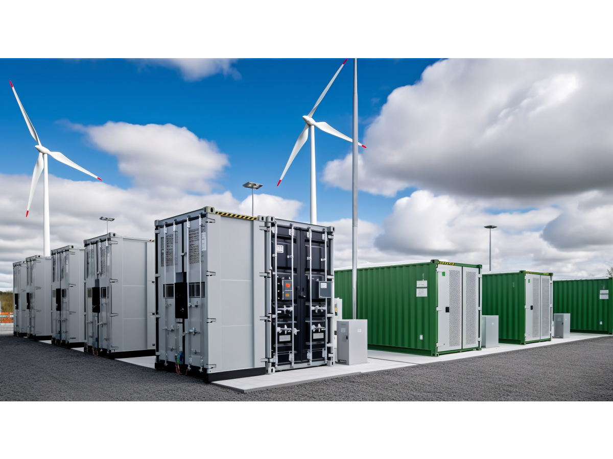
Wind turbines, photovoltaic systems, solar trackers, battery energy storage systems (BESS), inverters, power-conversion equipment,
and outdoor electrical enclosures operate under environmental conditions that are fundamentally different from indoor industrial machinery.
Product Specification
Wind turbines, photovoltaic systems, solar trackers, battery energy storage systems (BESS), inverters, power-conversion equipment,
and outdoor electrical enclosures operate under environmental conditions that are fundamentally different from indoor industrial machinery.
A plastic fastener or cable-management component used outdoors may experience years of combined exposure to ultraviolet radiation, thermal cycling,
humidity, condensation, wind-induced vibration, salt-laden air, dust, electrical equipment heat, and sustained mechanical loading.
For this reason, selecting renewable energy plastic fasteners should not begin with a simple question such as:
“Is this part made from nylon?”
The more useful engineering question is:
Where is the component installed, what load does it carry, how much sunlight and heat does it receive, is the cable static or moving, and what environmental exposure must the material survive?
Juxin Fasteners supplies standard and drawing-specific plastic fasteners, nylon cable clamps, P-clips, cable tie mounts, snap bushings,
insulating washers, spacers, standoffs, panel fasteners, and custom molded plastic components for renewable-energy equipment OEMs and industrial supply chains.
A practical selection path is:
Application Zone → Outdoor Exposure → Mechanical Load → Static or Dynamic Cable Duty → Temperature → UV / Moisture / Chemical Exposure → Material → Mounting Interface → Validation
This approach helps engineers avoid one of the most common renewable-energy hardware mistakes: specifying a general-purpose indoor plastic component for a long-term outdoor application.
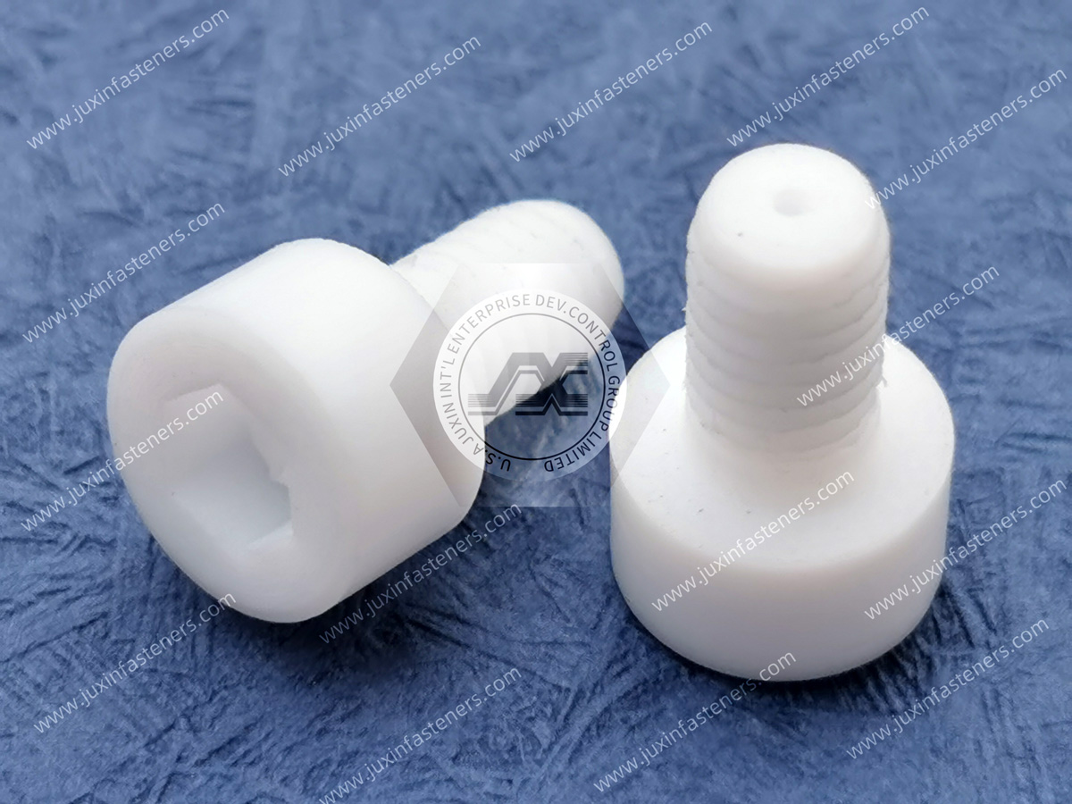
Plastic fastening and cable-management components may perform several different functions:
Retention + Routing + Spacing + Electrical Isolation + Edge Protection + Surface Protection + Assembly Simplification
Typical equipment includes:
wind turbines;
solar trackers;
photovoltaic electrical equipment;
inverter systems;
combiner boxes;
battery energy storage systems;
power conversion systems;
electrical cabinets;
monitoring equipment;
renewable-energy control systems.
The correct product family depends strongly on whether the component is installed inside a protected enclosure, inside a turbine nacelle, beneath a solar module, on an exposed tracker structure, or near power electronics.
A wind turbine nacelle contains:
power cables;
sensor wiring;
control harnesses;
communication lines;
cooling systems;
converters;
auxiliary electrical equipment.
Potential plastic cable-management hardware includes:
Heavy-Duty Nylon Cable Clamps & P-Clips;
adjustable cable clamps;
cable tie mounts;
wire clips;
snap bushings;
custom molded cable retainers.
These components may be used to maintain cable separation, prevent contact with structural edges, organize wiring, and reduce uncontrolled harness movement.
However, cable clamp selection must consider:
bundle diameter;
cable mass;
mounting orientation;
vibration;
local temperature;
mounting-hole geometry;
required service access.
A clamp that works for a light horizontal sensor cable may not be suitable for a heavy vertical power or control harness.
Converters, controllers, monitoring electronics, and auxiliary power equipment may require:
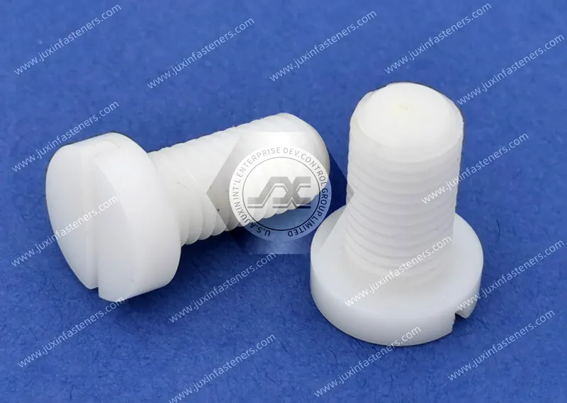
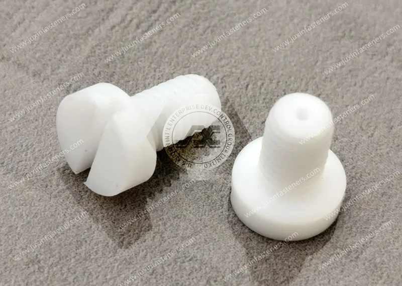
nylon machine screws;
insulating shoulder washers;
PCB supports;
plastic spacers;
standoffs;
snap bushings;
cable mounts.
Plastic components can provide local electrical isolation and prevent direct metal-to-metal contact.
They must not, however, be treated as replacements for the equipment's required:
protective grounding;
bonding;
creepage;
clearance;
insulation coordination;
electrical safety architecture.
Those requirements must be evaluated at system level according to the applicable equipment design and project standards.
Wind-turbine hardware may experience multiple sources of movement:
rotor-induced vibration;
gearbox or drivetrain vibration;
generator vibration;
tower movement;
start-stop events;
emergency stops;
transportation and installation shock.
For a plastic clamp or fastener, the engineering question is therefore not simply:
“Is the material vibration resistant?”
The actual questions include:
What mass is being retained?
What direction does the load act?
Is the load continuous or intermittent?
Does the component carry preload?
Can the cable move inside the clamp?
Is the polymer operating at elevated temperature?
Can creep reduce retention over time?
This load-path analysis provides more useful information than a generic “vibration-resistant” material description.
Large photovoltaic installations contain extensive DC wiring, monitoring cables, communication wiring, and auxiliary electrical systems.
Potential plastic components include:
cable clips;
cable tie mounts;
P-clips;
snap bushings;
panel fasteners;
custom cable retainers.
For exposed solar installations, material selection must consider:
UV radiation;
heat;
humidity;
rain;
freeze-thaw conditions;
wind;
dust;
mounting orientation.
Black color alone should not automatically be interpreted as proof of long-term UV stability.
The resin formulation and relevant weathering performance should be confirmed for the application.
Single-axis and dual-axis trackers introduce a different engineering problem.
The structure moves.
As the tracker rotates, cables may experience:
repeated bending;
torsion;
changing unsupported length;
sliding;
strain at fixed attachment points.
This creates an important distinction:
Static Cable Retention ≠ Dynamic Cable Guidance
A standard nylon P-clip or cable mount may be appropriate at a fixed attachment or transition point.
It should not automatically be used as the primary guiding device for a cable undergoing continuous tracker movement.
Dynamic tracker wiring may require a dedicated system that controls:
bend radius;
torsion;
cable slack;
movement envelope;
strain relief.
The plastic retention component must therefore be evaluated as one part of the complete cable-motion architecture.
Renewable-energy electrical enclosures may contain:
power electronics;
terminals;
control boards;
communication modules;
cooling systems;
high-density wiring.
Potential plastic hardware includes:
nylon machine screws;
insulating shoulder washers;
plastic spacers;
PCB supports;
cable tie mounts;
snap bushings;
strain-relief components.
Where cables pass through sheet-metal openings, sharp panel edges can damage insulation through:
installation abrasion;
vibration;
thermal movement;
service handling.
Nylon Snap Bushings can provide an insulated edge interface where appropriate.
Where external pulling forces may reach the cable termination, a dedicated strain-relief design should also be evaluated.
Utility-scale and commercial BESS equipment combines:
battery modules;
busbars;
battery management electronics;
cooling systems;
high-voltage wiring;
low-voltage signal wiring;
power conversion equipment;
enclosure systems.
Plastic hardware may support:
wire harness routing;
electronics spacing;
electrical isolation;
panel fastening;
PCB mounting;
cable entry protection.
Potential product families include:
nylon screws;
insulating washers;
spacers;
standoffs;
cable clamps;
snap bushings;
PCB supports;
custom molded plastic fasteners.
Material and component selection must be based on the actual BESS application.
A plastic fastener suitable for a low-voltage electronics compartment should not automatically be specified near high-current connections or high-temperature zones.
Not every renewable-energy component requires the same material.
A useful first distinction is:
Examples:
enclosed control cabinet;
protected nacelle compartment;
internal BESS electronics.
Primary concerns may include:
temperature;
electrical isolation;
flame behavior;
mechanical load;
creep;
vibration.
Examples:
ventilated enclosure;
protected underside of equipment;
sheltered cable-routing area.
Additional concerns may include:
humidity;
condensation;
indirect UV;
dust;
temperature cycling.
Examples:
solar tracker structure;
outdoor cable routing;
exterior sensor installation.
The design may need to consider:
direct UV;
rain;
wind;
freeze-thaw cycling;
thermal extremes;
pollutants;
salt exposure where applicable.
This zoning approach prevents unnecessary over-specification of protected components while avoiding under-specification of exposed hardware.
PA66 is widely used in industrial plastic fasteners and cable-management hardware because it can provide a useful combination of:
strength;
toughness;
fatigue resistance;
electrical insulation;
molding performance.
Potential applications include:
cable clamps;
P-clips;
snap bushings;
panel fasteners;
machine screws;
washers;
PCB supports.
For outdoor use, however, generic PA66 should not automatically be treated as weather-resistant.
Projects may require a specific:
UV-stabilized grade;
heat-stabilized grade;
impact-modified grade;
flame-retardant grade;
customer-specified resin.
POM may be considered where dimensional stability, low moisture absorption, low friction, or repeated mechanical movement is important.
Material suitability must still be reviewed against the actual outdoor and UV exposure.
PVDF may be considered for selected applications requiring enhanced chemical resistance or exposure to aggressive industrial environments.
PEEK may be considered for selected high-temperature, chemically demanding, or high-performance electrical equipment applications.
It should not be specified simply because it offers higher material performance.
The application must justify its mechanical, thermal, chemical, and commercial requirements.
A frequent procurement shortcut is to specify:
“Black nylon for outdoor use.”
This is incomplete.
Color and outdoor durability are not identical engineering properties.
A more useful specification identifies:
base polymer;
stabilizer package;
pigment system;
expected UV exposure;
temperature;
mechanical load;
required weathering validation.
For critical outdoor applications, engineers may request relevant accelerated weathering data using appropriate ASTM or ISO test methods.
The test method, exposure duration, specimen geometry, and acceptance criteria should be agreed for the project rather than assuming that any black polymer automatically meets a required outdoor lifetime.
UV degradation can cause:
surface embrittlement;
reduced elongation;
reduced impact resistance;
cracking;
color change.
For a decorative plastic cover, minor surface degradation may be acceptable.
For a loaded cable clip, the same degradation may reduce retention capability.
Therefore, renewable-energy hardware should be evaluated according to:
Weathering Exposure + Mechanical Function
not weathering exposure alone.
A lightly loaded spacer and a flexing snap clip made from the same polymer may have very different service risks.
Outdoor equipment can become substantially hotter than ambient air.
A plastic component mounted near:
dark metal structures;
inverter heat sources;
power electronics;
enclosed cabinets;
solar-heated surfaces
may operate above the published local air temperature.
Temperature influences:
stiffness;
creep;
stress relaxation;
impact behavior;
dimensional stability.
Engineers should therefore estimate or measure the local component temperature rather than selecting material solely from ambient climate data.
Renewable-energy equipment combines materials with very different thermal expansion behavior, including:
steel;
aluminum;
copper;
composites;
polymers.
During repeated heating and cooling, these materials expand and contract at different rates.
A polymer fastener rigidly constrained between metallic components may experience:
changing preload;
joint movement;
bearing stress;
creep;
fatigue.
The effect is particularly important in outdoor equipment experiencing repeated day-night thermal cycles.
PA66 is hygroscopic and absorbs moisture from its environment.
Moisture conditioning can affect:
stiffness;
toughness;
dimensions;
snap action;
insertion force;
creep behavior.
This means the performance of a PA66 clip immediately after molding may differ from its performance after environmental conditioning.
For precision snap-fit and retention applications, engineers should consider the material condition used during validation.
Outdoor renewable-energy equipment is expected to operate for extended periods with limited service access.
Plastic hardware under sustained stress can experience creep and stress relaxation.
Applications requiring particular attention include:
threaded plastic fasteners;
cable clamps;
loaded spacers;
snap features;
compressed insulating washers.
A component that survives an initial installation test may still lose retention after prolonged:
Load + Temperature + Time
Therefore, initial pull-out force alone is not sufficient for every long-life application.
Offshore wind equipment introduces additional exposure to:
salt spray;
high humidity;
condensation;
marine pollutants.
Polymer hardware can help eliminate galvanic contact at selected interfaces and does not rust like carbon steel.
However, “corrosion resistant” should not be interpreted as universal environmental immunity.
Engineers must still evaluate:
resin compatibility;
UV exposure;
temperature;
mechanical load;
chemical exposure;
water absorption.
Plastic components also do not replace metallic protective grounding or bonding paths required by the electrical system.
Plastic screws, spacers, shoulder washers, and standoffs can provide useful local electrical isolation.
Potential applications include:
control electronics;
PCB mounting;
sensor assemblies;
enclosure interfaces;
selected low-load insulated joints.
However:
A non-conductive fastener does not by itself establish compliance with creepage, clearance, insulation coordination, dielectric withstand, or high-voltage safety requirements.
Those properties depend on the complete geometry and electrical system.
Where IEC requirements apply, the equipment designer should define the relevant standard, pollution degree, voltage conditions, insulation system, and required test criteria.
A renewable-energy cable clamp should be selected using more than cable diameter.
Important inputs include:
cable OD;
bundle OD;
cable weight;
orientation;
static or moving duty;
wind exposure;
vibration;
temperature;
mounting-hole diameter;
mounting material;
expected service access.
Potential problems:
cable movement;
abrasion;
vibration noise;
impact against surrounding structure.
Potential problems:
jacket compression;
insulation damage;
excessive installation force;
clamp deformation.
The correct clamp should control movement without damaging the cable.
For snap-in hardware, performance depends on both the plastic component and the host structure.
Important dimensions include:
Hole Diameter + Panel Thickness + Edge Condition + Component Geometry
This applies to:
snap bushings;
push fasteners;
PCB supports;
cable tie mounts;
panel clips.
A visually similar replacement component may not provide equivalent retention if its locking geometry was designed for a different panel thickness.
| Application | Primary Requirement | Potential Product Family |
|---|---|---|
| Wind Nacelle Wiring | Vibration / Cable Retention | Nylon P-Clips / Cable Clamps |
| Solar Fixed Wiring | Outdoor Cable Management | Cable Clips / Cable Tie Mounts |
| Solar Tracker Wiring | Controlled Cable Transition | Application-Specific Cable Retainers |
| Inverter Enclosure | Isolation / Wire Organization | Nylon Screws / Mounts / Bushings |
| Combiner Box Entry | Edge Protection | Nylon Snap Bushings |
| BESS Electronics | Isolation / Spacing | Spacers / Standoffs / PCB Supports |
| Outdoor Access Panel | Corrosion-Free Fastening | Plastic Screws / Panel Fasteners |
| Custom Renewable Equipment | Geometry-Specific Function | Custom Molded Plastic Fasteners |
This matrix provides an initial selection path only.
Final approval should consider the actual environment, load, material, geometry, electrical requirements, and validation criteria.
Potential causes:
inadequate UV stabilization;
thermal aging;
unsuitable polymer grade.
Potential causes:
oversized loop diameter;
insufficient clamp force;
vibration;
incorrect mounting orientation.
Potential causes:
incorrect panel thickness;
oversized mounting hole;
creep;
thermal cycling.
Potential causes:
excessive initial preload;
elevated temperature;
stress relaxation;
sustained load.
Potential causes:
static clip used as dynamic guide;
insufficient bend radius;
excessive cable tension;
uncontrolled torsion.
Potential causes:
missing edge protection;
incorrect bushing size;
cable movement;
inadequate strain relief.
Failure-mode analysis helps engineering teams evaluate the complete assembly rather than focusing only on the component's catalog dimensions.
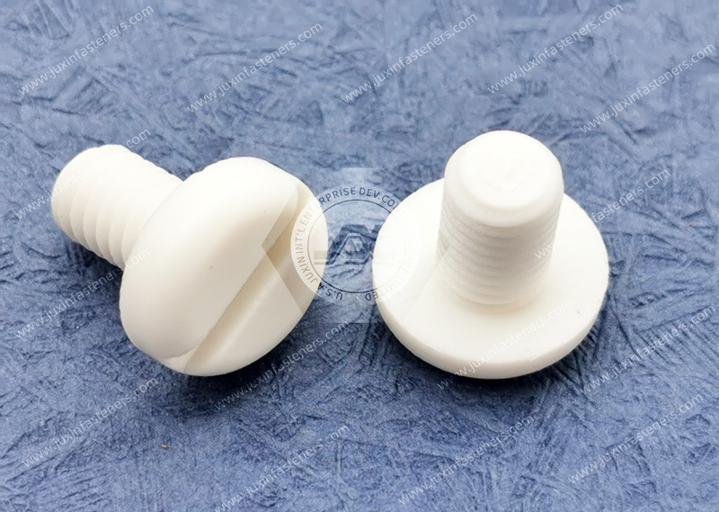
Renewable-energy OEMs frequently require alternative sources for existing components due to:
supply-chain risk;
localization;
cost control;
obsolete parts;
capacity requirements;
supplier consolidation.
A replacement part should be qualified using functional information rather than appearance alone.
Recommended inputs include:
existing OEM part number;
2D drawing;
3D CAD model;
physical sample;
material specification;
mounting-hole dimensions;
panel thickness;
cable diameter;
mechanical load;
static or dynamic duty;
operating temperature;
UV exposure;
humidity;
salt exposure where applicable;
electrical requirements;
required compliance documentation;
estimated annual usage.
For outdoor components, material equivalence is particularly important.
A dimensionally identical part molded from a different resin formulation may have very different long-term weathering performance.
Provide:
OEM part number;
drawing;
CAD model;
physical sample;
existing specification.
Define whether the part is installed:
inside a nacelle;
inside an inverter;
inside a BESS enclosure;
under a solar module;
on an exposed tracker;
in an offshore environment.
Provide:
thread size;
mounting-hole diameter;
panel thickness;
cable diameter;
bundle diameter;
spacer height;
critical tolerances.
Specify:
minimum temperature;
maximum local component temperature;
direct or indirect UV;
humidity;
condensation;
salt exposure;
chemicals;
dust.
For cable-management hardware, identify whether the cable is:
stationary;
occasionally moved;
continuously moving.
Potential requirements may include:
PA66;
UV-stabilized PA66;
heat-stabilized PA66;
POM;
PVDF;
PEEK;
customer-specified resin.
Where applicable, identify required:
ISO methods;
IEC equipment requirements;
ASTM weathering methods;
material documentation;
RoHS;
REACH;
customer-specific tests.
The specific standard and acceptance criteria should be defined by the project rather than assumed from the product family.
Evaluate:
dimensional fit;
installation force;
retention;
cable clamping;
panel engagement;
serviceability.
Where required, evaluate:
UV aging;
thermal cycling;
vibration;
humidity;
salt exposure;
creep;
repeated movement.
After technical approval, procurement can define:
sample quantity;
prototype volume;
production volume;
estimated annual usage;
packaging;
traceability;
delivery schedule;
inspection requirements.
A renewable-energy plastic component may have a low unit price but still create significant lifecycle cost if incorrectly specified.
A more useful sourcing equation is:
Component Cost + Installation Labor + Failure Risk + Maintenance Cost + Replacement Access + Supply Risk
For example, a low-cost cable clip installed deep inside a turbine nacelle may become expensive if premature failure requires field service.
Procurement decisions should therefore consider both:
Piece Price and Application Criticality
This is particularly important for equipment expected to remain in service for many years.
OEMs can often reduce procurement complexity by standardizing selected plastic hardware across product families.
Potential standardization opportunities include:
P-clip diameters;
cable tie mount footprints;
snap bushing sizes;
nylon screw families;
washer sizes;
spacer heights;
PCB support families.
Benefits may include:
fewer BOM items;
lower inventory complexity;
easier supplier qualification;
simpler service inventory;
consolidated annual purchasing volume;
improved second-source coverage.
For strategic sourcing teams, platform standardization can create greater long-term value than repeatedly sourcing many nearly identical low-volume components.
Standard catalog components cannot solve every wind, solar, inverter, or BESS application.
Custom molded or drawing-specific components may be required for:
proprietary cable-routing geometry;
special mounting holes;
unusual panel thicknesses;
combined clip-and-spacer functions;
custom standoff heights;
legacy equipment replacement;
equipment-specific enclosure interfaces.
Juxin Fasteners can support drawing-based sourcing for:
plastic screws;
nuts;
washers;
spacers;
standoffs;
cable clamps;
wire clips;
bushings;
panel fasteners;
custom molded plastic components.
Support can include:
2D drawing review;
3D CAD review;
physical sample comparison;
dimensional review;
material discussion;
DFM review;
sample evaluation;
production sourcing.
Availability of specific resins, weathering data, flame classifications, testing, certifications, and customer-specific documentation should be confirmed for each project.
For faster engineering and sourcing review, provide:
Application
wind, solar, BESS, inverter, or other equipment;
exact installation location;
static or dynamic duty.
Existing Part Information
OEM part number;
2D drawing;
3D CAD;
physical sample.
Dimensions
thread size;
part length;
mounting-hole diameter;
panel thickness;
cable or bundle diameter;
standoff height;
critical tolerances.
Environment
temperature range;
local component temperature;
direct UV exposure;
humidity;
condensation;
salt exposure;
chemical exposure.
Mechanical Requirements
load;
insertion force;
extraction force;
vibration;
shock;
expected movement.
Material
PA66;
UV-stabilized PA66;
heat-stabilized PA66;
POM;
PVDF;
PEEK;
customer-specified resin.
Electrical Requirements
electrical isolation;
voltage environment;
creepage or clearance constraints where applicable.
Compliance and Documentation
applicable ISO / IEC / ASTM requirements;
material documentation;
lot traceability;
RoHS / REACH where applicable;
customer-specific test requirements.
Procurement Information
sample quantity;
prototype quantity;
production quantity;
estimated annual usage;
delivery schedule.
Related Juxin Fasteners engineering and product pages include:
Heavy-Duty Nylon Cable Clamps & P-Clips for fixed cable retention;
Cable Tie Mounts for organized wire-harness routing;
Nylon Snap Bushings for sheet-metal cable-entry protection;
Nylon Machine Screws for electrically isolated equipment assembly;
Insulating Shoulder Washers for screw and chassis isolation;
Plastic Spacers and Standoffs for electronics and enclosure spacing;
Managing Polymer Creep & Stress Relaxation for long-term polymer joint design;
Custom Molded Plastic Fasteners for proprietary renewable-energy assemblies.
These pages should be internally linked from this renewable-energy solution page to create a structured conversion path:
Renewable Energy Application → Engineering Problem → Material / Product Decision → Product Family → Drawing / Sample → RFQ
Juxin Fasteners supports wind-energy equipment manufacturers, solar equipment OEMs, tracker manufacturers, inverter manufacturers,
BESS suppliers, electrical enclosure manufacturers, power-conversion equipment companies, contract manufacturers,
procurement teams, and supplier-development engineers requiring standard or drawing-specific plastic fastening and cable-management components.
The recommended sourcing workflow is:
Existing Part / Drawing / Sample → Application Zone → Outdoor Exposure → Static or Dynamic Duty → Mechanical Interface
→ Material Selection → Sample Evaluation → Environmental Validation → Documentation Review → Second-Source Qualification → Production RFQ
This process can support:
new renewable-energy equipment development;
second-source qualification;
supplier consolidation;
cable-routing optimization;
electrical-isolation requirements;
obsolete-part replacement;
outdoor material upgrades;
platform standardization;
custom plastic component development.
Send us your existing part number, 2D drawing, 3D CAD model, physical sample, mounting-hole dimensions, panel thickness,
cable diameter, operating temperature, UV exposure, vibration conditions, static or dynamic duty, material requirement,
applicable standards, documentation requirements, prototype quantity, production quantity, and estimated annual usage for engineering review and RFQ evaluation.
Email: info@juxinfasteners.com
Website: www.juxinfasteners.com
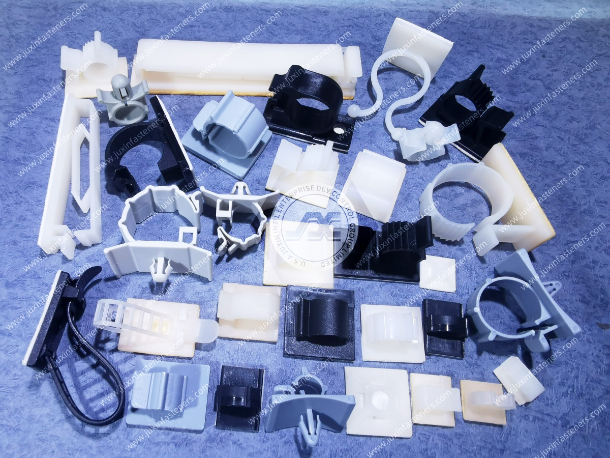
Product Packaging
Packaging Standard
At Juxin Fasteners, we apply standardized export packaging to ensure product protection, traceability, and compliance with international logistics requirements.
1. Standard Export Packaging
Unless otherwise specified, all products will be packed according to our factory standard export packaging, which includes:
Moisture-resistant inner protection
Poly bag or small box packing as required
Reinforced export cartons
Clear labeling with part number, specification, batch number, and quantity
Palletizing for sea or air shipment when necessary
Our standard packaging is designed to ensure safe transportation, efficient warehousing, and long-distance international shipping.
2. Customized Packaging Options
We also provide customized packaging solutions according to customer requirements, including but not limited to:
Private labeling
Customized barcodes
Specific carton dimensions
Retail packaging
Special pallet configuration
Customer-specific marking and identification
So that you know, customized packaging may involve additional costs and extended lead time depending on the complexity of the requirements.
3. Compliance & Quality Assurance
All packaging processes are controlled under our ISO 9001 quality management system to ensure consistency, traceability, and product integrity throughout the supply chain.
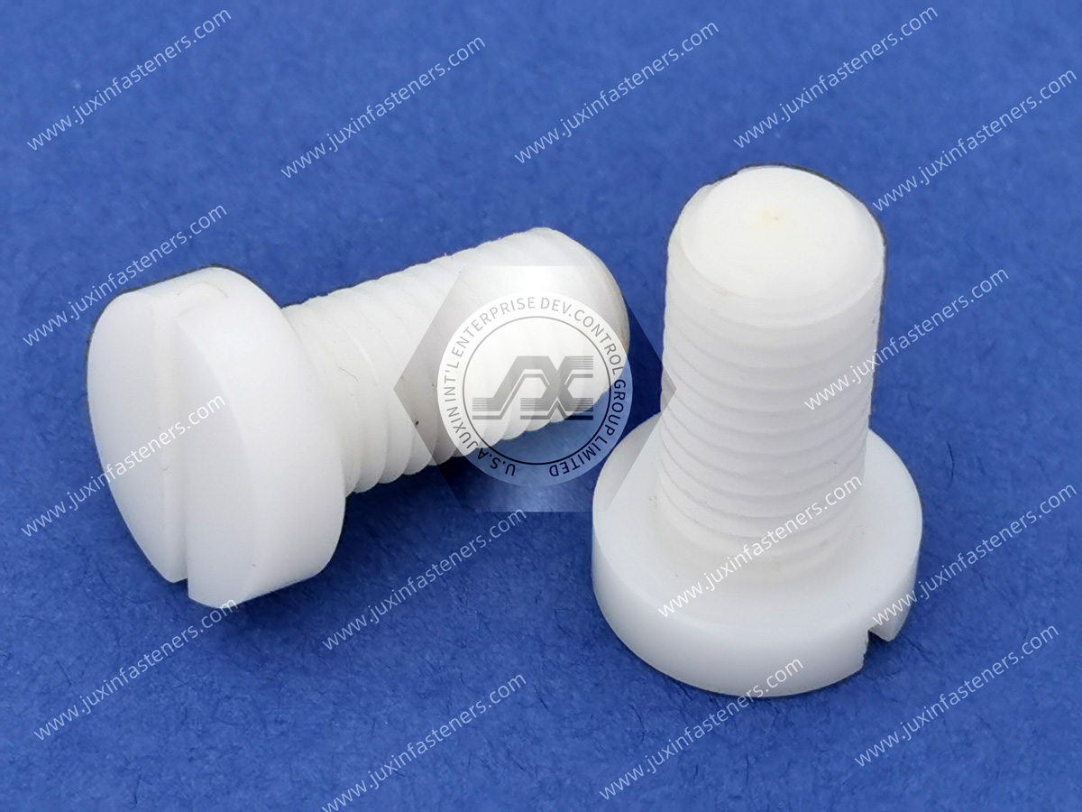
Product Pictures
Contact Us
Tel.:
+86 020 8621 0320
+86 020 3121 6067
E-mail:
Technical Support:
Navigation
SEND INQUIREY