Call Us
+86 136 6007 9809
Call Us
+86 136 6007 9809

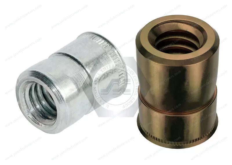
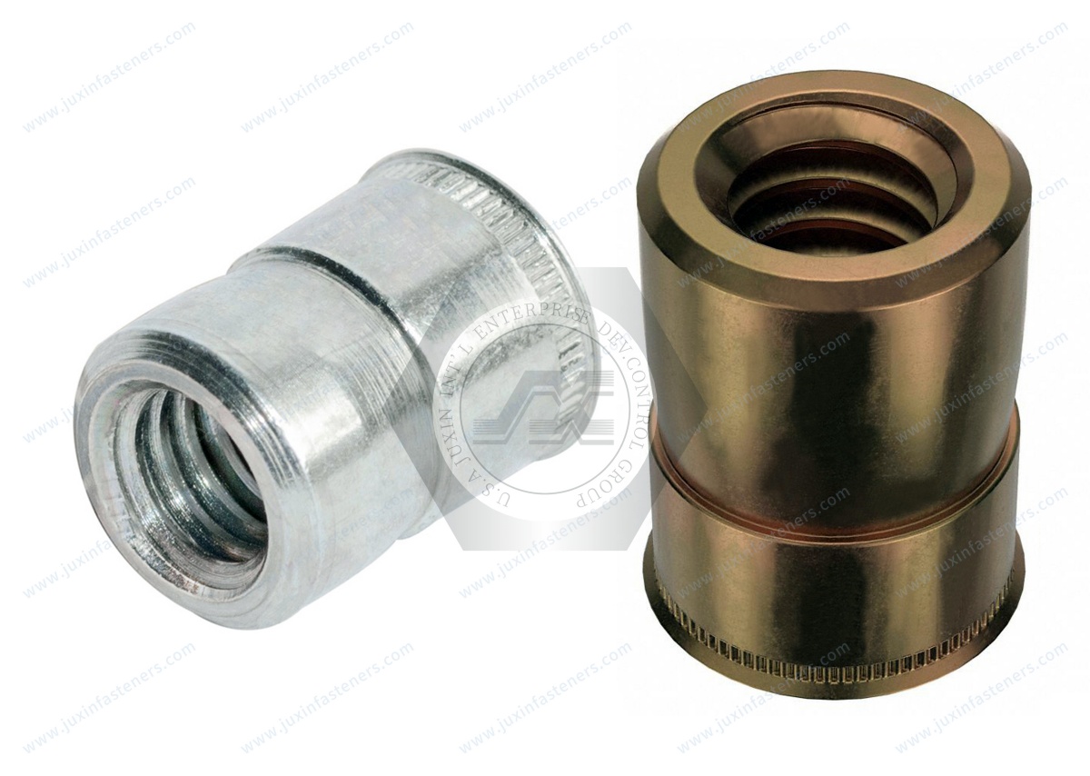
JUXIN FASTENERS supplies steel thin head blind rivet nuts, also searched as tight-space rivet nuts, for creating internal threads in sheet metal and enclosures with limited installation access. The reduced-profile flange helps minimize head projection, while the collapsible body forms a retaining feature behind the panel during one-sided installation. Available in metric and Unified inch thread sizes with a blue-white zinc finish, these inserts can be evaluated for commercial foodservice equipment, telecommunications housings, electrical cabinets, automotive assemblies and railway equipment.
Product Type: Thin Head Blind Rivet Nut / Internal Threaded Insert
Material: Steel (grade subject to confirmation)
Surface Finish: Blue-White Zinc (RoHS compliance subject to verification)
Metric Threads: M3, M4, M5, M6, M8, M10, M12
Unified Threads: #4-40, #6-32, #8-32, #10-24, #10-32, 1/4-20
Grip Range: 0.5–5.5 mm (product family; verify by part number)
Head Type: Thin Head / Low-Profile Flange
Installation: One-Sided Mechanical Blind Riveting
Product Specification
Product Specifications — Steel Thin Head Tight-Space Blind Rivet Nuts
JUXIN FASTENERS supplies steel thin head blind rivet nuts for OEM applications requiring internal threaded fastening points in sheet metal, thin panels and fabricated enclosures.
These fasteners are also searched for as tight-space rivet nuts, low-profile rivet nuts, thin flange threaded inserts and blind threaded insert nuts.
Their main function is to create a retained female thread where the rear side of the parent material cannot be accessed during installation.
The thin head helps reduce projection above the accessible panel surface. During installation, the deformable rivet body collapses behind the panel to create mechanical retention.
This combination can be useful for equipment housings, service panels, mounting brackets and compact assemblies.
However, a thin head does not automatically mean that the rivet nut has a shorter body, requires less blind-side clearance or provides flush mounting. Those characteristics must be confirmed from the actual product drawing.
Technical Product Specifications
Product Name: Steel Thin Head Blind Rivet Nut
Alternative Search Names: Tight-Space Rivet Nut, Thin Flange Rivet Nut, Low-Profile Blind Threaded Insert
Material: Steel
Steel Grade: Subject to approved specification
Surface Finish: Blue-White Zinc
RoHS Compliance: Subject to verification of the supplied coating system
Head Configuration: Thin Head / Reduced-Profile Flange
Thread Configuration: Internal Female Thread
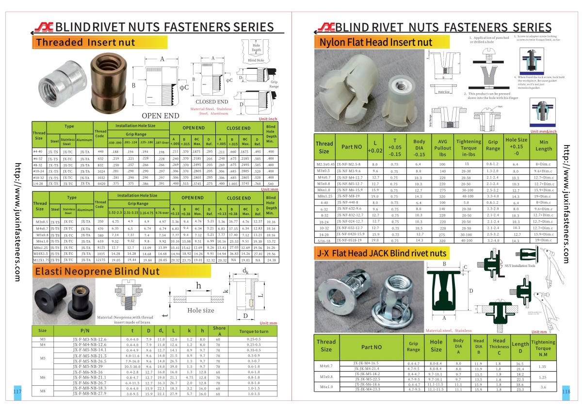
Metric Thread Sizes: M3, M4, M5, M6, M8, M10, M12
Unified Inch Thread Sizes: #4-40, #6-32, #8-32, #10-24, #10-32, 1/4-20
Grip Range: 0.5–5.5 mm across the product family
Body Geometry: According to approved drawing
Mounting-Hole Dimensions: According to approved drawing
Installed Blind-Side Projection: Subject to dimensional verification
Installation Method: One-Sided Mechanical Blind Riveting
Mechanical Performance: Subject to application-specific qualification
Packaging: According to confirmed purchasing requirements
The stated grip range is product-family information. Availability, grip range and dimensional characteristics must be verified for each individual thread size and part number.
What Are Tight-Space Rivet Nuts?
Tight-space rivet nuts are blind threaded inserts selected for assemblies with restricted access, limited packaging space or other geometric constraints.
They create a permanent internal threaded mounting point without requiring access to the rear of the panel during installation.
The rivet nut is inserted into a prepared mounting hole.
A compatible installation tool engages the internal thread and applies the required setting action.
The deformable body collapses behind the panel, creating a mechanical retaining feature.
After the tool is removed, a bolt or screw can be installed into the retained female thread.
The term tight-space describes an application requirement rather than a universal dimensional standard.
Different manufacturers may use the term for products with different head thicknesses, body lengths and installation characteristics.
For engineering selection, the actual dimensions and installed clearance must take priority over the marketing name.
Thin Head Design and Near-Flush Mounting
A thin head rivet nut has a reduced-profile flange compared with a corresponding conventional flange configuration.
The main potential benefit is reduced projection above the accessible panel surface.
This can help when:
A cover must fit close to the parent panel
A bracket requires limited stand-off
Internal equipment clearance is restricted
Adjacent components are closely positioned
A compact enclosure has limited assembly space
However, thin head does not necessarily mean flush.
A true flush installation depends on the installed head geometry and the surrounding panel design.
The engineer should confirm head thickness, head diameter, mating-component clearance and any required recess geometry.
A thin head also should not automatically be treated as mechanically equivalent to a larger flange.
Engineering Information Gain — Three Different Types of Space Constraint
A common selection mistake is treating all tight-space fastening problems as the same.
In practice, engineers should distinguish three separate clearance conditions.
Accessible-Side Clearance
This is the available space above the panel surface.
A thin head may help reduce interference with mating components.
Blind-Side Clearance
This is the available space behind the panel.
The rivet body must have enough room to deform during installation and remain clear of internal components.
Tool Access Clearance
This is the space needed for the installation tool, mandrel, nosepiece and operator or automation equipment.
A rivet nut may fit the panel but still be impossible to install because the setting tool cannot reach the hole.
These three dimensions should be checked separately.
A thin flange primarily addresses accessible-side head projection. It does not independently establish reduced blind-side clearance or tool-access requirements.
Blind-Side Clearance Before and After Installation
Blind-side clearance is especially important in compact equipment housings.
The engineer should consider both the fastener's uninstalled body length and its geometry after setting.
Relevant dimensions include:
Overall uninstalled body length
Grip thickness
Deformable body section
Installed blind-side projection
Clearance to internal components
Space required during installation
Tool stroke and installation method
The required clearance cannot be determined from thread size alone.
For example, two M5 rivet nuts may have different body lengths and installed projections.
Where clearance is critical, the supplier should provide the relevant drawing and the installation should be validated in a representative assembly.
Thin Head vs. Flat Head vs. Countersunk Rivet Nuts
Thin Head Rivet Nuts
Designed with a reduced-profile flange to limit accessible-side head projection.
Conventional Flat Head Rivet Nuts
May provide a different flange thickness and bearing geometry.
Countersunk Rivet Nuts
Designed to seat within a compatible prepared recess, subject to the actual head and countersink dimensions.
The correct selection depends on panel thickness, bearing requirements, manufacturing capability and clearance.
A countersunk configuration should not automatically be selected for very thin panels without checking the remaining material around the prepared recess.
A thin head may avoid some recess preparation requirements, but the actual mounting-hole design must still be confirmed.
Thread Size Selection — Metric and Unified Inch Threads
The confirmed metric thread sizes are:
M3
M4
M5
M6
M8
M10
M12
The confirmed Unified inch thread sizes are:
#4-40 UNC
#6-32 UNC
#8-32 UNC
#10-24 UNC
#10-32 UNF
1/4-20 UNC
The actual thread designation and tolerance must be confirmed from the approved part specification.
ISO 261 and ISO 965 are relevant references for ISO metric thread series and tolerances.
ASME B1.1 is a relevant reference for Unified inch screw threads.
Metric and Unified threads are different systems and are not directly interchangeable.
Approximate nominal diameter references:
M3 = 0.118 in
M4 = 0.157 in
M5 = 0.197 in
M6 = 0.236 in
M8 = 0.315 in
M10 = 0.394 in
M12 = 0.472 in
These values are dimensional conversions only, not equivalent inch thread designations.
Why #10-24 and #10-32 Are Different
The #10-24 and #10-32 thread sizes share the same nominal major diameter but have different thread pitches.
#10-24 has 24 threads per inch.
#10-32 has 32 threads per inch.
The difference affects mating screw compatibility.
A #10-24 screw should not be forced into a #10-32 rivet nut.
For OEM purchasing, the complete thread designation must be included on the drawing, purchase order and inspection documentation.
The same principle applies when comparing metric threads with similar nominal diameters.
Grip Range — 0.5–5.5 mm
The supplied product-family grip range is 0.5–5.5 mm.
Approximate inch references:
0.5 mm = 0.020 in
5.5 mm = 0.217 in
Grip range refers to the parent-material thickness that the selected rivet nut is designed to accommodate.
It is not the same as overall body length or installed blind-side projection.
Different thread sizes and body configurations may have different approved grip ranges.
The actual part number must be selected according to the panel thickness.
An incorrect grip selection can lead to:
Incomplete body deformation
Poor head seating
Insufficient retention
Excessive panel distortion
Inconsistent installed performance
The complete thickness of the material being gripped should be evaluated.
Mounting-Hole Size and Panel Preparation
The mounting hole is a critical part of the installation system.
Its dimensions must be compatible with the selected rivet nut body.
Relevant characteristics include:
Hole diameter or specified profile
Hole tolerance
Parent-material thickness
Hole position
Edge distance
Burr condition
Local flatness
Coating thickness
Material hardness
An oversized hole may reduce installed retention or rotational resistance.
An undersized hole may prevent insertion or damage the rivet nut.
For thicker parent materials, hole preparation and installation behavior should be evaluated using the actual product specification.
A larger hole should not be recommended automatically without a drawing-based requirement.
Body Geometry and Anti-Rotation Selection
Blind rivet nuts may be manufactured with different body configurations.
Examples include smooth round, knurled, partially hexagonal and full hexagonal designs.
These configurations use different mechanisms to resist rotation.
Smooth Round Body
Installed rotational resistance depends on body deformation, contact conditions and the parent material.
Knurled Body
Raised exterior features may engage the parent material and contribute to resistance against rotation.
Partial Hexagonal Body
A polygonal section may engage a compatible mounting-hole geometry.
Full Hexagonal Body
A more extensive polygonal body may provide geometric engagement with a corresponding hole.
The supplied product description does not establish which specific body configuration applies to every size shown.
Body geometry must be confirmed from the approved drawing before specifying mounting-hole dimensions or installed spin-out performance.
Steel Material and Blue-White Zinc Finish
The confirmed base material is steel.
The exact grade and material condition have not been specified.
The confirmed surface treatment is described as RoHS blue-white zinc.
Blue-white zinc is a commercial finish description, not a complete coating specification.
The actual requirements may include:
Zinc coating system
Coating thickness
Conversion coating
Supplemental treatment
Surface appearance
Corrosion requirements
Thread dimensional compatibility
Restricted-substance compliance
ISO 4042 provides a relevant framework for electroplated coating systems on steel fasteners where applicable.
The actual coating designation must be established through the approved specification.
The finish description alone does not prove RoHS compliance.
Corrosion Protection and Environmental Suitability
Zinc coatings can provide corrosion protection to steel fasteners.
Actual performance depends on the coating system and operating environment.
For foodservice equipment, engineers should distinguish between dry interior components and areas exposed to frequent cleaning, moisture or aggressive chemicals.
For telecommunications equipment, indoor and outdoor installations may have different environmental requirements.
For electrical and power distribution equipment, enclosure conditions and environmental exposure should be evaluated.
For automotive and railway equipment, vibration, moisture, contaminants and maintenance conditions may affect selection.
Where corrosion testing is specified, ISO 9227 or ASTM B117 may provide relevant testing methods.
No specific salt-spray rating or service-life guarantee is claimed.
Hydrogen Embrittlement and Electroplated Steel
Certain electroplating processes can introduce hydrogen into steel components.
For susceptible materials, hydrogen may contribute to delayed cracking under specific conditions.
The relevance depends on steel strength, hardness, manufacturing history, coating process and applied stress.
Because the exact steel grade and hardness have not been supplied, no product-specific hydrogen embrittlement classification is claimed.
Where applicable, the approved material and coating requirements should address relevant risk controls.
One-Sided Installation Process
A typical blind rivet nut installation sequence includes:
Confirm the selected part number and grip range.
Prepare the mounting hole according to the approved drawing.
Inspect the hole size and edge condition.
Verify the parent-material thickness.
Fit the correct threaded mandrel and nosepiece to the setting tool.
Engage the rivet nut's internal thread.
Insert the rivet nut into the prepared mounting hole.
Seat the thin flange against the accessible panel surface.
Apply the approved setting stroke or force.
Deform the rivet body behind the panel.
Release the tool.
Inspect the installed insert before assembling the mating screw.
The actual installation procedure depends on the fastener design and setting equipment.
Hand and Power Rivet Nut Installation Tools
Blind rivet nuts may be installed using compatible manual or powered equipment.
Tool selection should consider:
Thread size
Rivet nut material
Body geometry
Grip range
Setting stroke
Required installation force
Tool access
Production volume
Inspection requirements
For compact enclosures, the installation tool may be a more significant space constraint than the fastener itself.
Before production approval, the OEM should confirm that the tool can access the mounting location without damaging nearby components.
Pull-Out Resistance and Spin-Out Torque
Installed performance should be evaluated as part of the complete fastening system.
Pull-Out Resistance
Describes resistance to axial extraction of the installed rivet nut.
Spin-Out Torque
Describes resistance to rotation of the installed rivet nut within the parent material.
Thread Strength
Concerns the ability of the internal thread to support the required mating screw connection.
These characteristics depend on:
Rivet nut geometry
Material
Panel thickness
Parent-material properties
Hole dimensions
Installation deformation
Thread engagement
Applied loading
No universal pull-out rating, spin-out torque or thread-strength value is claimed.
A thin head should not automatically be described as equally strong as a conventional flange design.
Performance must be established through appropriate product-specific data or application testing.
Engineering Information Gain — Why Thin Panels Can Fail Even When the Rivet Nut Is Correct
An OEM engineer may select a rivet nut with the correct thread size, material and nominal grip range.
However, the installed joint may still perform poorly.
Possible causes include:
Oversized mounting hole
Inconsistent hole quality
Insufficient parent-material strength
Excessive local panel deformation
Incorrect setting stroke
Inadequate blind-side clearance
Mating screw bottoming out
Excessive tightening torque
This demonstrates why rivet nut selection must consider the entire assembly.
The fastener drawing, parent-panel drawing, installation process and mating screw requirements should be evaluated together.
Commercial Foodservice and Catering Equipment
Thin head rivet nuts may be evaluated for selected commercial kitchen and foodservice equipment assemblies.
Potential applications include:
Equipment access panels
Internal mounting brackets
Control housings
Removable covers
Fabricated support components
Serviceable sheet-metal assemblies
Relevant engineering considerations include:
Restricted internal space
Repeated service access
Moisture exposure
Cleaning conditions
Material compatibility
Corrosion requirements
Equipment hygiene requirements where applicable
Zinc-coated steel should not automatically be selected for direct food-contact areas or aggressive washdown environments.
The actual material and finish must be approved for the intended equipment conditions.
Telecommunications Equipment and Network Enclosures
Telecommunications equipment frequently uses compact fabricated enclosures and closely spaced components.
Potential applications include:
Communication cabinets
Network equipment housings
Equipment mounting brackets
Service access panels
Internal accessory supports
Sheet-metal equipment frames
Selection considerations include:
Limited accessible-side clearance
Blind-side component interference
Installation-tool access
Serviceability
Corrosion exposure
Grounding or electrical bonding requirements
The rivet nut alone does not establish electrical continuity or grounding performance.
Those requirements must be evaluated at assembly level.
Electrical Cabinets and Power Distribution Equipment
Thin head blind rivet nuts may be considered for selected electrical and power equipment components.
Potential applications include:
Electrical control cabinets
Distribution equipment enclosures
Instrument housings
Mounting brackets
Equipment covers
Internal support structures
Engineering considerations include:
Panel thickness
Electrical clearances
Tool access
Mechanical retention
Corrosion protection
Vibration
Grounding and bonding requirements
Use in electrical equipment must comply with the applicable equipment design and approval requirements.
No electrical safety certification is implied.
Automotive OEM and Tier 1 Assemblies
Thin head rivet nuts may be evaluated for selected automotive sheet-metal and equipment applications.
Potential uses include:
Interior equipment brackets
Serviceable covers
Fabricated housings
Accessory mounting points
Non-safety-critical support components
Automotive engineers should consider:
Vibration
Installation repeatability
Assembly torque
Panel material
Corrosion requirements
Service access
Drawing revision control
Customer-specific qualification
Automotive safety-critical use requires separate engineering approval and validation.
No automotive OEM approval or PPAP status is claimed without supporting documentation.
Railway and Rolling Stock Equipment
Railway equipment may require retained threaded inserts in fabricated metal panels and serviceable enclosures.
Potential applications include selected:
Interior equipment housings
Electrical cabinets
Communications equipment enclosures
Access panels
Non-structural mounting brackets
Maintenance-access components
Railway applications may involve additional requirements for vibration, fatigue, corrosion, fire performance, electrical systems or customer-specific approvals.
A standard industrial rivet nut should not automatically be considered qualified for railway use.
The relevant application and project specifications must be reviewed.
Engineering Example — Compact Telecommunications Enclosure
Consider a telecommunications equipment enclosure requiring an M4 internal threaded attachment point.
The enclosure has limited clearance above the panel and restricted access behind it.
A thin head blind rivet nut may be considered.
The engineer should confirm:
Parent-panel material
Actual panel thickness
Required M4 thread specification
Mounting-hole dimensions
Head thickness and diameter
Uninstalled body length
Installed blind-side projection
Installation-tool access
Grip range
Required screw engagement
Mating screw length
Assembly torque
Axial retention
Rotational resistance
Coating and corrosion requirements
A compact head alone does not guarantee that the rivet nut will fit inside the enclosure.
The installed body geometry and tool access must also be verified.
Engineering Example — Serviceable Commercial Kitchen Equipment Panel
Consider a commercial foodservice equipment manufacturer designing a removable sheet-metal access panel.
The design requires an internal threaded connection that can be assembled from the accessible side.
A thin head blind rivet nut may help reduce interference between the panel and the mating component.
However, the engineer should assess:
Actual panel thickness
Hole preparation
Fastener grip range
Head projection
Repeated maintenance requirements
Screw engagement
Cleaning exposure
Corrosion conditions
Required installed retention
Where the equipment is exposed to moisture or frequent chemical cleaning, material and coating suitability must be evaluated before selecting zinc-coated steel.
Procurement Information Gain — A Rivet Nut Price Comparison Must Include Installation Cost
For OEM procurement, the lowest unit price may not represent the lowest installed cost.
Two thin head rivet nuts with the same nominal thread size may require different:
Mounting-hole dimensions
Installation mandrels
Setting strokes
Installation forces
Grip ranges
Head clearances
Blind-side clearances
Inspection procedures
A lower-priced substitute may require tooling changes or additional qualification.
For supplier comparison, purchasing teams should consider:
Fastener unit price
Hole preparation cost
Installation cycle time
Tool compatibility
Scrap and rework risk
Quality documentation
Qualification cost
Delivery reliability
Packaging requirements
Long-term supply consistency
This approach is especially valuable for high-volume equipment manufacturing.
OEM and Supplier Qualification Requirements
Depending on the customer and application, supplier qualification may include:
Approved engineering drawing
Material specification
Thread inspection
Head dimensions
Body dimensions
Grip-range verification
Mounting-hole compatibility
Installation-tool compatibility
Installed pull-out testing
Installed spin-out testing
Thread engagement verification
Coating specification
Corrosion testing where required
Restricted-substance documentation
Lot traceability
Drawing revision control
The required tests and acceptance limits should be defined by the customer or approved engineering specification.
No particular certification, test result or production approval is implied.
Drawing-Based OEM Requirements
Customer-specific requirements may include:
Defined metric or Unified inch thread
Special head thickness
Specific flange diameter
Modified body length
Application-specific grip range
Defined steel grade
Customer-approved coating system
Controlled mounting-hole dimensions
Installed performance requirements
Inspection documentation
Lot identification
Packaging and labeling requirements
Any nonstandard configuration is subject to technical review and manufacturing feasibility confirmation.
Frequently Asked Questions
What are tight-space rivet nuts?
They are blind threaded inserts selected for applications with restricted space or access. The actual head, body and installation dimensions determine suitability.
Are tight-space rivet nuts the same as thin head rivet nuts?
The terms may overlap in commercial use, but they are not necessarily identical product specifications.
Can thin head rivet nuts be installed from one side?
Yes. Blind rivet nuts are designed for mechanical installation from the accessible side using compatible equipment.
Do thin head rivet nuts provide flush mounting?
Not automatically. Actual head projection and panel geometry must be verified.
Are these rivet nuts shorter than standard rivet nuts?
Not necessarily. The actual body length and installed blind-side projection must be confirmed from the drawing.
Are thin head rivet nuts as strong as conventional rivet nuts?
Strength depends on the actual design, material, panel and installation. Equivalent performance cannot be assumed.
What metric sizes are available?
The confirmed family includes M3, M4, M5, M6, M8, M10 and M12.
What inch thread sizes are available?
The confirmed family includes #4-40, #6-32, #8-32, #10-24, #10-32 and 1/4-20.
Can metric and inch rivet nuts be interchanged?
No. The mating thread system, pitch and tolerance must match.
What is the grip range?
The supplied family range is 0.5–5.5 mm. Individual part-number grip ranges must be verified.
Is blue-white zinc automatically RoHS compliant?
No. Compliance must be verified through appropriate documentation for the actual coating system.
Can these rivet nuts be used in commercial kitchen equipment?
They may be evaluated for suitable equipment assemblies, but the material, coating and cleaning environment must be reviewed.
Can they be used in railway equipment?
They may be considered for suitable applications, subject to project-specific engineering and qualification requirements.
Related Industrial Fastening Solutions
Engineers comparing blind threaded inserts may also consider these related JUXIN FASTENERS product categories.
Flat Head Blind Rivet Nuts — for applications where conventional flange geometry is suitable.
Countersunk Blind Rivet Nuts — for assemblies requiring a compatible recessed head installation.
Knurled Body Blind Rivet Nuts — for alternative body engagement characteristics.
Hexagonal Body Blind Rivet Nuts — for polygonal mounting-hole engagement.
Stainless Steel Blind Rivet Nuts — for applications requiring a different material system.
Blind Rivet Studs — for one-sided assemblies requiring external male threads.
Self-Clinching Nuts — for suitable press-installed sheet-metal applications.
Weld Nuts — for applications designed around an approved welding process.
Custom Industrial Fasteners — for drawing-based OEM requirements.
These product names can serve as contextual internal-link anchor texts. Links should be added only after the corresponding live page addresses have been verified.
OEM RFQ Checklist
For accurate technical review and quotation, please provide:
Required thread size and thread system
Engineering drawing or CAD file
Required steel grade
Blue-white zinc coating specification
Parent-panel material
Panel thickness
Required grip range
Mounting-hole dimensions
Head diameter and thickness
Body geometry and overall length
Available blind-side clearance
Installation-tool access
Required pull-out resistance
Required spin-out torque
Mating screw specification
Assembly torque requirements
Corrosion or compliance documentation requirements
Initial order quantity
Estimated annual demand
Inspection, packaging and delivery requirements
For established OEM projects, providing the existing part drawing and installation conditions helps determine whether a proposed rivet nut is technically interchangeable.
JUXIN FASTENERS — OEM Thin Head Rivet Nut Supply
JUXIN FASTENERS supplies industrial fastening products for OEM engineers, procurement managers, supplier development teams and international equipment manufacturers.
Our steel thin head blind rivet nuts are intended for sheet-metal assemblies requiring internal threaded mounting points and one-sided installation.
The available product family includes metric and Unified inch thread sizes for evaluation in commercial foodservice equipment, telecommunications enclosures, electrical equipment, industrial machinery, automotive assemblies and railway equipment.
For OEM purchasing and technical inquiries, submit the product drawing, installation conditions, material and coating requirements, and required purchasing quantities.
Request an OEM Technical Quotation
Email: info@juxinfasteners.com
Website: www.juxinfasteners.com
Please include your required thread size, panel thickness, mounting-hole dimensions, head-clearance requirements, available blind-side space and estimated annual demand.
JUXIN FASTENERS — Industrial Fastening Solutions for OEM Engineering and Global Procurement.
Product Packaging
Product Packaging — Steel Thin Head Blind Rivet Nuts
Packaging for steel thin head blind rivet nuts is subject to confirmed product specifications, purchasing quantities and OEM supply-chain requirements.
Protective Packaging: Suitable packaging may be specified to help protect internal threads, thin flange surfaces and zinc-coated bodies during handling and transportation.
Outer Cartons: Carton arrangements may be reviewed according to product quantity, shipment weight and handling requirements.
Pallet Packaging: Palletized arrangements may be considered for bulk industrial shipments, subject to confirmation.
Product Identification: Customer-specified labels may identify the part number, thread size, material, surface finish, quantity, lot number and drawing revision.
Metric and Inch Thread Segregation: Packaging and identification requirements should distinguish metric and Unified inch thread sizes to reduce the risk of mixing incompatible parts.
Lot Traceability: Batch identification and traceability requirements should be established in the approved purchasing and quality documentation.
OEM Packaging: Customer-specific packing quantities, labeling, component segregation and logistics instructions are subject to review and confirmation.
Final packing quantities, carton arrangements and shipping details will be confirmed against the approved order.
For OEM packaging requirements and quotations:
Email: info@juxinfasteners.com
Website: www.juxinfasteners.com
Product Pictures
Tags
Contact Us
Tel.:
+86 020 8621 0320
+86 020 3121 6067
E-mail:
Technical Support:
Navigation
SEND INQUIREY