Call Us
+86 136 6007 9809
Call Us
+86 136 6007 9809

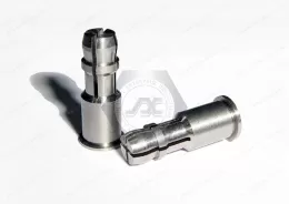
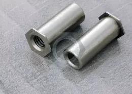
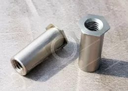
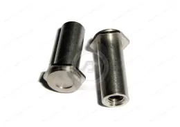
JUXIN FASTENERS supplies JX-SOAG and JX-SOSG self-clinching grounding standoffs for PCB mounting and electrical bonding to steel or aluminum chassis.
These stainless steel grounding standoffs are installed into properly prepared sheet-metal holes using a controlled pressing operation.
Their projecting annular teeth contact the mating PCB grounding area, combining mechanical spacing with an electrical bonding interface.
Available thread options include M3, M4, and selected Unified #4 and #6 sizes. Listed stainless steel material options include SUS302, SUS303, SUS316, SUS410, SUS420, and SUS430, subject to product specifications.
For special lengths greater than 12 mm, the product information identifies blind-threaded configurations. Custom dimensions can be reviewed according to the approved drawing.
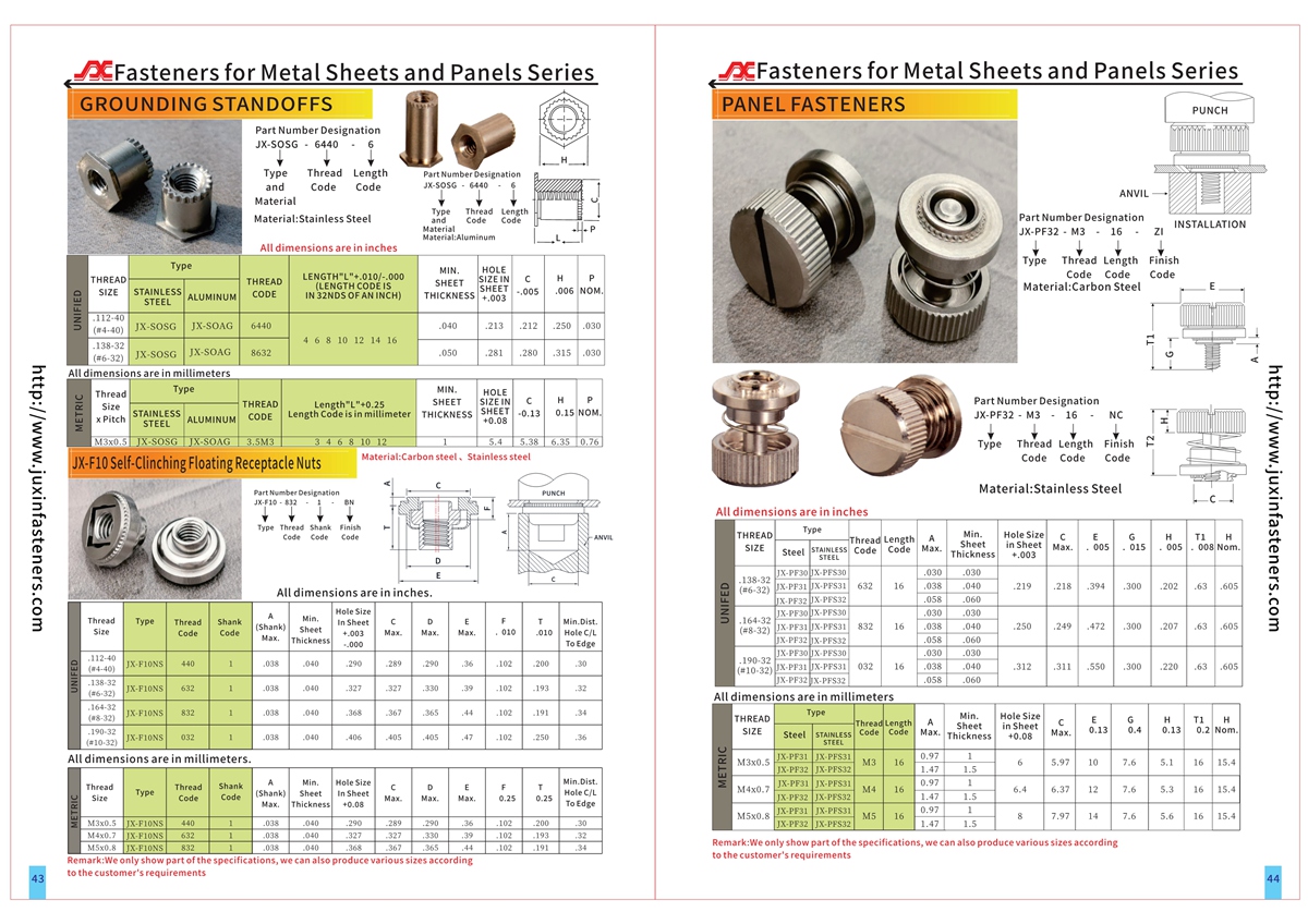
Refer to the product PDF and CAD specifications on pages 43–44 for detailed dimensions, installation requirements, and available configurations.
Product Specification
PCB Grounding Self-Clinching Standoffs – JX-SOAG / JX-SOSG
Electrical Bonding and Mechanical Support for PCB-to-Chassis Assemblies
JUXIN FASTENERS provides JX-SOAG and JX-SOSG self-clinching grounding standoffs for industrial electronic equipment requiring a reliable mechanical connection between printed circuit boards and metal chassis.
Unlike conventional PCB spacers that primarily establish mounting height, grounding standoffs incorporate a dedicated electrical contact interface.
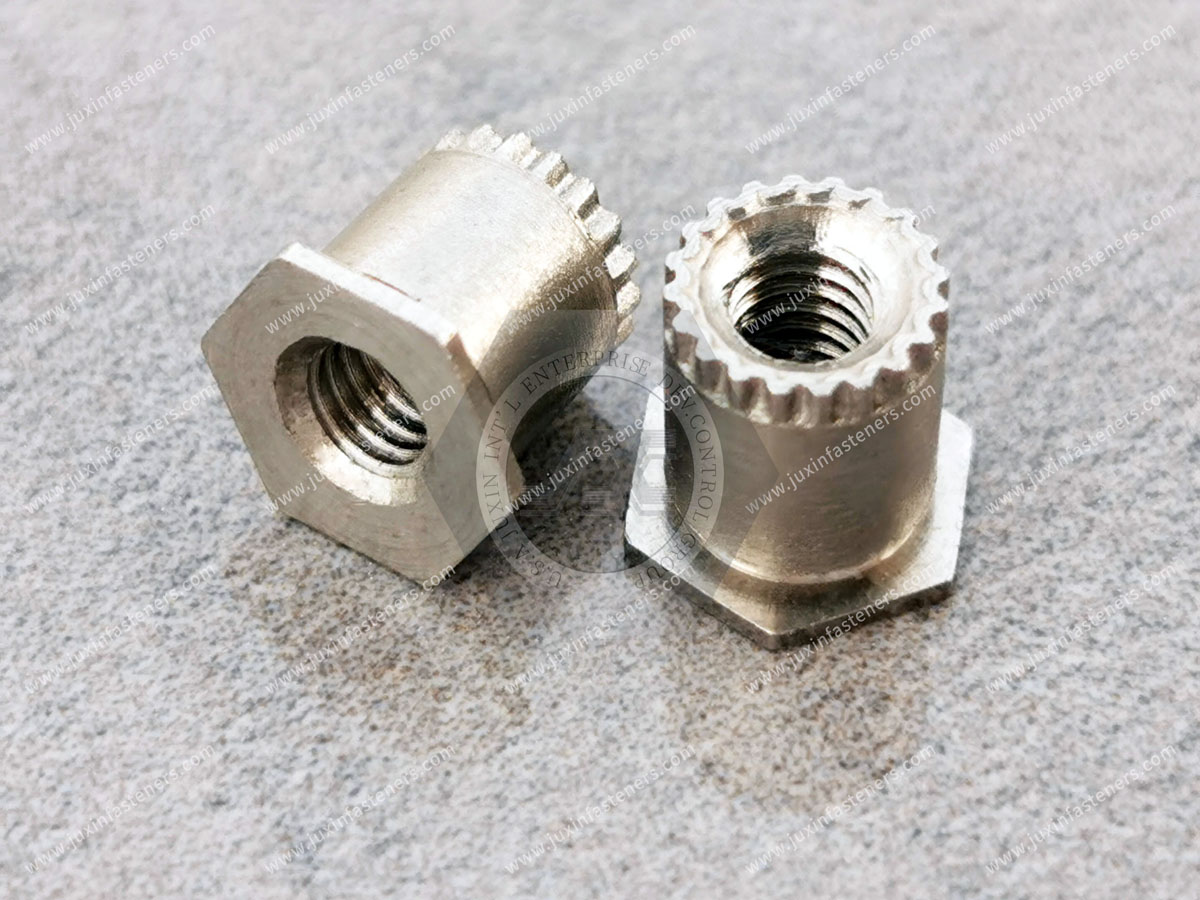
The JX-SOAG and JX-SOSG designs feature projecting annular teeth at the PCB-facing end.
These teeth are intended to contact the designated conductive area of the mating circuit board when the assembly is properly fastened.
The opposite end uses a self-clinching attachment to secure the standoff in a compatible steel or aluminum chassis.
This arrangement can combine PCB support, mounting-point retention, and electrical bonding within a single fastener.
Electrical performance depends on the complete assembly, including the PCB contact finish, chassis material, installation quality, mating screw, clamping force, and operating environment.
Product Overview
Product series: JX-SOAG / JX-SOSG
Product type: Self-clinching grounding standoffs
Primary application: PCB-to-chassis grounding and mechanical support
Installation method: Press installation into prepared sheet-metal holes
Compatible chassis materials: Suitable steel or aluminum sheets, subject to installation specifications
Grounding interface: Projecting annular contact teeth
Listed thread sizes: M3, M4, and Unified #4 and #6
Material family: Stainless steel
Special configurations: Custom lengths subject to review
Thread configuration: Special lengths greater than 12 mm are identified as blind threaded in the supplied product information
Technical dimensions: Refer to product drawings and CAD specifications, pages 43–44
Material Options
Listed stainless steel grades include SUS302, SUS303, SUS316, SUS410, SUS420, and SUS430.
These grades differ in corrosion resistance, mechanical properties, machinability, magnetic behavior, and suitability for self-clinching applications.
The actual material grade and condition must be confirmed for the selected JX-SOAG or JX-SOSG configuration.
Austenitic, ferritic, and martensitic stainless steels should not be treated as interchangeable without reviewing the installation and electrical contact requirements.
Material selection must also consider galvanic compatibility with the chassis, surface finish, environmental exposure, and applicable customer specifications.
How PCB Grounding Standoffs Work
A grounding standoff provides a controlled mechanical spacing distance while creating a conductive interface between the PCB grounding area and the chassis assembly.
The self-clinching end is pressed into a correctly sized mounting hole.
During installation, sheet material flows into the designated retention features of the fastener, securing it within the metal panel.
The PCB is subsequently positioned over the standoff.
When the mating screw is tightened, the annular teeth at the upper end contact the designated conductive region of the circuit board.
These teeth are intended to establish metal-to-metal contact with an appropriate PCB grounding pad.
This arrangement can eliminate the need for a separate serrated or star washer at that interface in designs where the contact performance has been validated.
However, eliminating a washer does not automatically establish compliance with an electrical bonding requirement.
The assembled joint must still be assessed for contact resistance, mechanical retention, environmental durability, and applicable electrical safety requirements.
The Difference Between a Grounding Standoff and a Standard PCB Standoff
A standard PCB standoff primarily supports the board at a specified distance from the chassis or another component.
A grounding standoff performs the same spacing function while incorporating a contact geometry intended to establish an electrical connection.
This distinction is important because a conventional metallic spacer does not necessarily provide consistent electrical contact.
PCB solder mask, surface contamination, protective coatings, insufficient clamping force, and local geometry can interfere with conductivity.
The annular teeth of a grounding standoff are designed to contact the intended conductive region more directly.
Nevertheless, the PCB grounding pad must be designed specifically for this connection.
The standoff should not be assumed to create a reliable electrical path through ordinary solder mask or other insulating materials.
PCB Grounding Pad Design
The mating PCB should include a suitable conductive contact area around the mounting hole.
The grounding pad must be dimensioned to accommodate the standoff contact teeth and the expected assembly tolerances.
The design should consider the diameter of the tooth contact region, the PCB hole location, the conductive surface finish, and the relationship between the pad and the intended ground network.
A conductive pad that is too small may result in incomplete contact.
An incorrectly positioned pad may allow the teeth to contact solder mask or another nonconductive region.
The PCB designer must also determine whether the mounting point should connect to chassis ground, circuit ground, a defined grounding network, or remain isolated.
These decisions are part of the electrical architecture and should not be made solely on the basis of the fastener material.
For multilayer circuit boards, the grounding connection should be coordinated with the PCB layout, via arrangement, copper geometry, and applicable electrical design rules.
Electrical Bonding and Contact Resistance
The electrical function of a grounding standoff depends on the quality of the conductive interfaces.
A typical PCB-to-chassis bonding path may include the PCB grounding pad, the annular contact teeth, the standoff body, the self-clinched chassis interface, and the chassis itself.
Each interface can contribute resistance.
Even where the fastener is made from conductive metal, coatings, oxides, contamination, or insufficient mechanical contact may affect the final connection.
The electrical resistance of the installed assembly should therefore be measured where grounding performance is important.
A useful engineering approach is to evaluate the assembled joint before and after representative mechanical or environmental exposure.
The test method and acceptance limit should be defined by the OEM according to the application.
No universal milliohm value should be assigned without an approved performance specification.
EMI and EMC Design Considerations
PCB grounding standoffs may form part of an electromagnetic compatibility strategy.
They can provide a conductive connection between a circuit board and a metal enclosure at designated mounting locations.
Such connections may be useful for chassis referencing, shielding continuity, or other grounding functions.
However, EMI and EMC performance depends on the complete equipment design.
Ground path geometry, connection impedance, cable routing, enclosure construction, frequency range, and PCB layout all influence the result.
A low DC contact resistance does not by itself prove adequate high-frequency bonding performance.
The number and location of grounding points should therefore be established by the electrical design team.
For products subject to electromagnetic compatibility testing, the assembled equipment must be validated against the applicable requirements.
Grounding Standoffs for Steel and Aluminum Chassis
JX-SOAG and JX-SOSG grounding standoffs are intended for installation into compatible steel or aluminum chassis.
The self-clinching connection requires the chassis material to deform appropriately during pressing.
Installation behavior depends on the hardness, thickness, ductility, hole geometry, and surface condition of the metal sheet.
A material that is too hard may not flow correctly into the fastener retention features.
An unsuitable mounting hole can reduce pushout resistance or rotational retention.
The minimum sheet thickness and maximum substrate hardness must be taken from the relevant product drawing.
Steel and aluminum chassis may also have different surface treatments.
Paint, powder coating, anodizing, plating, and other finishes can affect electrical bonding.
The electrical design must therefore consider whether the standoff-to-chassis interface provides the intended conductive path after all finishing and assembly operations.
Installation and Pressing Requirements
Self-clinching grounding standoffs are installed using a controlled squeezing force between suitable parallel tooling surfaces.
The mounting hole must be prepared according to the applicable fastener specification.
The standoff is positioned in the hole and supported by the appropriate installation tooling.
The press then applies sufficient force to embed the retention features without damaging the fastener or deforming the surrounding chassis beyond the permitted limits.
Correct installation should be evaluated through dimensional inspection and, where required, mechanical retention testing.
The use of a standard press does not eliminate the need for correct tooling, force control, and alignment.
The installed fastener should not be subjected to secondary operations that could compromise the retention geometry or electrical interface without engineering approval.
Annular Teeth and Contact Pressure
The projecting annular teeth are a defining feature of this grounding standoff family.
Their purpose is to create localized contact with the PCB grounding region.
The contact pressure is influenced by the tooth geometry, the mating surface, the screw clamping load, and the stiffness of the assembled components.
Insufficient clamping may produce an unstable electrical interface.
Excessive clamping can damage the PCB, deform the contact region, or overstress the threaded connection.
The correct tightening requirement should therefore be established using the actual screw, standoff, PCB, and chassis combination.
The teeth should not be described as guaranteeing electrical continuity under every operating condition.
Thread Sizes and International Standards
The listed thread options include M3, M4, and selected Unified #4 and #6 sizes.
Metric thread geometry may be specified using applicable ISO 261 and ISO 965 requirements.
Unified inch-series threads may be specified according to ASME B1.1.
Metric and Unified thread systems are not interchangeable.
The exact thread pitch, tolerance class, mating screw, and available engagement depth must be confirmed from the approved drawing.
Special lengths greater than 12 mm are identified as blind threaded in the supplied product information.
For these configurations, the internal thread depth must be reviewed to prevent screw bottoming and ensure the required clamping force can be achieved.
The final screw length should account for the PCB thickness, washers where used, thread engagement, and dimensional tolerances.
Special Lengths and OEM Configurations
Different PCB assemblies require different spacing distances.
The required standoff height may depend on component clearance, enclosure dimensions, connector positioning, airflow, and service accessibility.
A custom standoff length should be evaluated together with the PCB layout and mating hardware.
Longer standoffs may also increase bending loads at the chassis attachment point.
The effect of lateral loading, vibration, and board stiffness should be considered when the mounting arrangement is mechanically demanding.
JUXIN FASTENERS can review custom-length requirements based on drawings and manufacturing feasibility.
Electrical and mechanical performance must be verified for the final configuration.
Industrial Applications
Industrial Automation and Control Cabinets
Grounding standoffs can support printed circuit boards within industrial control equipment while providing designated conductive connections to a steel or aluminum chassis.
These applications may include controller modules, power-management boards, and monitoring electronics.
Telecommunications and Networking Equipment
Metal-enclosed communication equipment frequently requires controlled PCB mounting positions and defined chassis connections.
Grounding standoffs may be considered for suitable equipment designs where mechanical spacing and electrical bonding are required at the same mounting location.
Power Electronics
Power conversion and distribution equipment may require PCB support structures with carefully designed grounding interfaces.
The suitability of a grounding standoff depends on electrical safety requirements, current paths, thermal conditions, and the overall enclosure design.
Industrial Measurement Instruments
Electronic measurement systems may incorporate grounding points intended to support shielding or other electrical functions.
The placement and performance of these connections should be determined by the instrument's electrical design.
Embedded Computing Equipment
Industrial computers and electronic control modules often combine compact PCB layouts with metal housings.
Grounding standoffs can offer a space-efficient mounting option where the selected PCB grounding pad and chassis construction are compatible.
Transportation and Equipment Electronics
Electronic assemblies exposed to vibration or temperature variation may require mechanically secure PCB supports.
Grounding standoffs may be considered where both retention and electrical contact performance can be validated under the expected service conditions.
Engineering Example: PCB Mounted in an Aluminum Enclosure
Consider an industrial control module containing a PCB mounted above an aluminum enclosure base.
The mechanical design requires a fixed distance between the PCB and the enclosure to provide clearance for underside components.
The electrical design also requires a designated conductive connection between the PCB grounding network and the chassis.
A conventional spacer could establish the mounting height, but the grounding connection might require an additional contact component or a separately validated bonding arrangement.
A JX-SOAG or JX-SOSG grounding standoff may provide both functions at the same location.
The engineer must first confirm that the aluminum sheet thickness and hardness are suitable for self-clinching installation.
The PCB designer must then provide a compatible conductive pad at the contact location.
The assembly team must establish the correct screw length and clamping conditions.
Finally, the installed joint should be evaluated for mechanical retention and electrical continuity.
This example illustrates why grounding standoff selection must involve both mechanical and electrical engineering.
Grounding Standoff vs. Star Washer
A star washer is often used to create localized contact pressure at a bolted electrical connection.
A grounding standoff incorporates contact teeth directly into the fastener geometry.
This may reduce the number of separate components and simplify assembly.
However, the two solutions should not be considered universally interchangeable.
Their contact geometry, clamping behavior, surface compatibility, and long-term electrical performance can differ.
The correct choice depends on the required connection performance and assembly validation.
Grounding Standoff vs. Ordinary Self-Clinching Standoff
An ordinary self-clinching standoff is primarily designed to establish a retained mechanical spacing point in sheet metal.
A grounding standoff adds a dedicated PCB-facing electrical contact feature.
Where electrical bonding is not required, a standard standoff may be sufficient.
Where electrical bonding is required, a grounding standoff may reduce the need for additional contact hardware, provided that the assembly meets the applicable requirements.
Neither design should be selected without reviewing the mounting substrate, board geometry, mechanical loading, and required electrical function.
OEM Procurement and Supplier Qualification
For OEM purchasing teams, the correct grounding standoff specification should include more than the thread size and overall length.
The electrical contact interface, chassis compatibility, and installation requirements are equally important.
A sourcing review should confirm the following information:
Product reference: JX-SOAG or JX-SOSG
Thread size and tolerance
Required standoff length
Blind or through-thread configuration
Approved stainless steel material grade
Chassis material, thickness, and hardness
Mounting-hole dimensions
PCB grounding pad geometry
Mating screw and assembly requirements
Required mechanical retention performance
Electrical contact or bonding test requirements
Surface treatment and environmental conditions
Engineering drawings and revision level
Sample approval and inspection requirements
Estimated order quantity and annual purchasing demand
Packaging and identification requirements
These details help procurement teams compare technically equivalent offers and reduce the risk of approving a part that fits dimensionally but does not meet the electrical bonding requirements.
Quality Verification
A suitable quality plan may include dimensional verification, thread inspection, material confirmation, and installation-related checks.
Where electrical bonding is a functional requirement, the OEM should define an appropriate contact resistance test and acceptance criteria.
For applications involving vibration, temperature cycling, or corrosive environments, additional testing may be required.
Relevant international standards should be selected according to the actual test objective.
For example, ISO 9227 or ASTM B117 may be referenced when a salt-spray exposure method is appropriate, but neither standard alone establishes the electrical reliability or service life of a grounding connection.
Electrical safety and EMC compliance must be evaluated at the appropriate assembly or equipment level.
Frequently Asked Questions
What is a PCB grounding standoff?
A PCB grounding standoff is a mechanical spacing fastener designed to support a circuit board while providing a conductive contact interface to a compatible chassis assembly.
What is the purpose of the annular teeth?
The projecting teeth are intended to contact the designated conductive area of the PCB and establish a mechanical electrical interface when the assembly is correctly clamped.
Can grounding standoffs replace star washers?
They may eliminate the need for a separate star washer in a validated design. The required electrical and mechanical performance must still be confirmed.
Can JX-SOAG and JX-SOSG be installed into aluminum chassis?
The product family is intended for compatible steel or aluminum chassis. The applicable sheet thickness, hardness, and mounting-hole requirements must be verified.
Are grounding standoffs suitable for EMI and EMC applications?
They may contribute to an equipment grounding or shielding strategy. Overall EMI and EMC performance depends on the complete electrical and mechanical design.
What thread sizes are available?
The supplied product information lists M3, M4, and selected Unified #4 and #6 sizes. Exact configurations should be confirmed against the technical drawing.
Are special lengths available?
Custom lengths can be reviewed. The supplied information identifies blind-threaded configurations for special lengths greater than 12 mm.
Does stainless steel automatically guarantee a good grounding connection?
No. The installed electrical path depends on contact geometry, surface condition, clamping force, chassis construction, and the complete assembly.
Related Industrial Fastening Solutions
Self-Clinching Standoffs
For retained mechanical spacing and mounting points in compatible metal panels.
Close-to-Edge Self-Clinching Standoffs – JX-DSO / JX-DSOS
For specialized mounting arrangements requiring reduced edge-distance considerations.
PCB Broaching Standoffs
For mounting and spacing applications involving compatible printed circuit board substrates.
PCB Broaching Nuts
For internally threaded mounting points in suitable PCB materials.
Self-Clinching Nuts
For reusable threaded attachment points in compatible sheet-metal assemblies.
Blind Threaded Standoffs
For applications requiring controlled screw penetration and closed-end threaded mounting.
These related product categories can be connected to their corresponding JUXIN FASTENERS product pages to support technical comparison and internal navigation.
Request a Grounding Standoff Quotation
JUXIN FASTENERS supplies industrial fastening solutions for OEM equipment manufacturers, electronic assembly businesses, engineering teams, and international procurement organizations.
For JX-SOAG and JX-SOSG grounding standoff inquiries, please provide the required thread size, standoff length, chassis material, sheet thickness, PCB grounding requirements, drawings, and expected order quantity.
Our team can review the application requirements and provide a quotation based on the confirmed technical specification.
Email: info@juxinfasteners.com
Website: www.juxinfasteners.com
JUXIN FASTENERS – Industrial Fastening and PCB-to-Chassis Grounding Solutions.
Product Packaging
JX-SOAG and JX-SOSG grounding standoffs are packed using protective inner packaging and export cartons, with palletized shipping arrangements where required.
Packaging methods are selected according to product dimensions, order quantities, and customer requirements to help protect threads and grounding contact features during handling and transportation.
Custom carton quantities, labeling, part-number identification, and OEM packaging specifications can be reviewed before order confirmation.
For bulk orders and packaging inquiries, contact info@juxinfasteners.com.
Website: www.juxinfasteners.com
Product Pictures
Contact Us
Tel.:
+86 020 8621 0320
+86 020 3121 6067
E-mail:
Technical Support:
Navigation
SEND INQUIREY