Call Us
+86 136 6007 9809
Call Us
+86 136 6007 9809

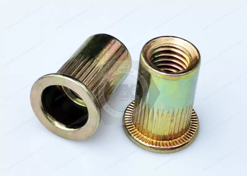
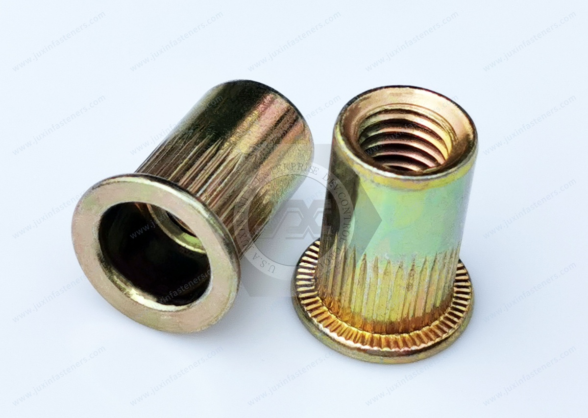
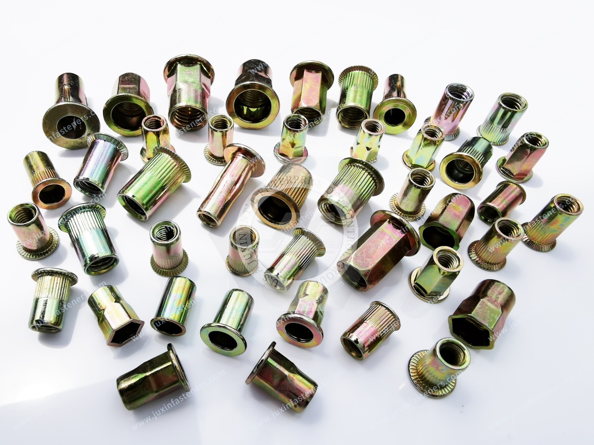
JUXIN FASTENERS manufactures flat head, open-end steel blind rivet nuts with knurled round bodies for creating internal threads in thin sheet metal, hollow sections, and industrial assemblies requiring one-sided installation.
The knurled body provides additional mechanical engagement with compatible mounting materials, helping resist insert rotation. During installation, the body deforms behind the panel to create a retained threaded attachment point without welding.
Product Features
Thread sizes: M3, M4, M5, M6, M8, M10, M12
Material: Steel
Surface finish: Color zinc plating
Grip range: 0.5–6.5 mm across the product family, depending on configuration
Head style: Flat head / Flanged head
Body style: Knurled round body
End style: Open end
Installation: One-sided blind installation
Typical applications include automotive brackets, electrical enclosures, control cabinets, industrial machinery, sheet-metal housings, and OEM assemblies requiring improved rotational resistance.
Product Specification
Technical Specifications — Knurled Steel Blind Rivet Nuts
Product Identification
| Parameter | Specification |
|---|---|
| Product Type | Flat Head Open-End Knurled Blind Rivet Nut |
| Alternative Names | Ribbed Body Rivet Nut / Knurled Rivnut / Blind Threaded Insert |
| Material | Steel |
| Metric Thread Sizes | M3, M4, M5, M6, M8, M10, M12 |
| Head Configuration | Flat Head / Flanged Head |
| Body Configuration | Knurled Round Body |
| End Configuration | Open End |
| Surface Treatment | Color Zinc Plating |
| Published Series Grip Range | 0.5–6.5 mm (approximately 0.020–0.256 in) |
| Installation | One-Sided Blind Rivet Nut Setting |
| Mounting Hole Diameter | Refer to approved drawing |
| Knurl Geometry | Refer to approved drawing |
| Flange Diameter and Height | Refer to approved drawing |
| Body Length | Refer to approved drawing |
| Custom Requirements | Subject to technical review |
Metric Thread Sizes and US Inch Reference
The following table provides standard ISO metric coarse thread pitches and approximate inch equivalents.
| Metric Thread | Pitch (mm) | Pitch (in) | Nominal Diameter (in) |
|---|---|---|---|
| M3 | 0.50 | 0.0197 | 0.1181 |
| M4 | 0.70 | 0.0276 | 0.1575 |
| M5 | 0.80 | 0.0315 | 0.1969 |
| M6 | 1.00 | 0.0394 | 0.2362 |
| M8 | 1.25 | 0.0492 | 0.3150 |
| M10 | 1.50 | 0.0591 | 0.3937 |
| M12 | 1.75 | 0.0689 | 0.4724 |
These values are dimensional references only. ISO metric threads are not interchangeable with UNC or UNF threads.
Applicable metric thread references may include ISO 261, ISO 724, and ISO 965, subject to the approved drawing.
Imperial Thread Requirements — US OEM Applications
The existing product information also lists several Unified inch thread sizes.
The following designations should be confirmed against the applicable product drawings before being treated as available catalog specifications.
| Inch Thread Designation | Threads Per Inch | Verification Status |
|---|---|---|
| #6-32 UNC | 32 | Drawing confirmation required |
| #8-32 UNC | 32 | Drawing confirmation required |
| 1/4-20 UNC | 20 | Drawing confirmation required |
| 3/8-16 UNC | 16 | Drawing confirmation required |
| 1/2-13 UNC | 13 | Drawing confirmation required |
An additional designation in the original information, 5/15-18, requires clarification and has not been included as a confirmed specification.
Unified inch threads should be defined according to applicable ASME B1.1 requirements.
Metric and Unified thread systems must not be substituted for one another without engineering approval.
Grip Range — Metric and Imperial Reference
The published product-series grip range is 0.5–6.5 mm (approximately 0.020–0.256 in).
| Panel Thickness (mm) | Approximate Thickness (in) |
|---|---|
| 0.5 | 0.0197 |
| 1.0 | 0.0394 |
| 1.5 | 0.0591 |
| 2.0 | 0.0787 |
| 2.5 | 0.0984 |
| 3.0 | 0.1181 |
| 4.0 | 0.1575 |
| 5.0 | 0.1969 |
| 6.0 | 0.2362 |
| 6.5 | 0.2559 |
These are conversion references, not approved grip ranges for individual part numbers.
Each selected configuration must be checked against its technical drawing.
Engineering Selection and Installation Guide
1. How Knurling Improves Anti-Rotation Engagement
The knurled surface creates local geometric features along the rivet nut body.
During installation, these features may engage the surrounding panel material and increase resistance to rotation.
The effectiveness of this engagement depends on:
Knurl depth and profile
Panel material hardness
Mounting hole diameter and tolerance
Installation stroke or force
Rivet nut body deformation
Grip range
Surface coating condition
A knurled rivet nut should not automatically be considered suitable for high-torque applications without testing.
2. Knurled Body Versus Smooth Body
| Engineering Factor | Knurled Body | Smooth Body |
|---|---|---|
| Body Surface | Textured / Ribbed | Smooth |
| Anti-Rotation Engagement | Additional geometric engagement possible | Primarily installation deformation and friction |
| Mounting Hole | Drawing-specific round hole | Drawing-specific round hole |
| Panel Interaction | Knurl engagement may affect local material deformation | No intentional knurl engagement |
| Spin-Out Performance | Requires testing | Requires testing |
| Typical Selection Priority | Additional anti-rotation resistance | Standard smooth-body fastening requirements |
Actual performance must be evaluated under representative assembly conditions.
3. Mounting Hole Diameter and Tolerance
Mounting hole preparation is critical to the performance of knurled rivet nuts.
An oversized hole may prevent sufficient engagement between the knurled surface and panel material.
An undersized hole may damage the coating, interfere with insertion, or cause excessive local deformation.
Engineers should verify:
Nominal hole diameter
Hole tolerance
Hole roundness
Burr condition
Panel thickness
Panel material hardness
Knurl outer diameter
Use the approved product drawing to determine the correct hole dimensions.
4. Panel Material and Knurl Engagement
Knurled rivet nuts can behave differently in steel, aluminum, and other mounting materials.
Relatively soft materials may allow greater local engagement with the knurled surface, but they may also deform under installation or tightening loads.
Harder panels may provide different retention behavior and require careful setting process control.
For plastic or composite materials, evaluate local damage, creep, and long-term retention before approval.
5. Spin-Out Torque and Repeated Assembly
Spin-out resistance is the ability of an installed rivet nut to resist rotation relative to the mounting panel.
It is especially important when the mating screw is repeatedly tightened or removed.
For OEM validation, consider testing:
Initial spin-out torque
Spin-out behavior after repeated assembly
Panel deformation
Thread integrity
Installation consistency
Performance under representative service conditions
Acceptance criteria should be established according to the intended joint design.
6. Pull-Out Resistance and Flange Support
Pull-out resistance depends on the installed backside deformation, panel material, hole geometry, and rivet nut dimensions.
The flat head provides a bearing surface against the mounting panel.
However, the flange alone does not determine the complete joint's axial strength.
For thin or soft panels, evaluate local bearing deformation and possible pull-through.
7. Grip Range and Panel Thickness
The published grip range is 0.5–6.5 mm (approximately 0.020–0.256 in) across the product series.
Individual sizes and body lengths may have different approved grip ranges.
For multilayer assemblies, verify the combined thickness and intended clamping configuration.
Do not assume that every thread size covers the complete published range.
8. Installation Procedure
Confirm the selected rivet nut matches the approved drawing.
Prepare the specified mounting hole.
Remove burrs and inspect the panel surface.
Select a compatible rivet nut setting mandrel.
Insert the knurled body into the mounting hole.
Seat the flange against the panel.
Hold the installation tool perpendicular to the surface.
Apply the approved setting stroke or force.
Inspect the backside deformation and flange seating.
Verify thread integrity and rotational retention where required.
Manual, pneumatic, or automated installation methods may be considered when compatible with the selected product and approved process.
9. Open-End Thread Engagement
The open-end design allows a mating screw to extend through the threaded barrel when sufficient backside clearance exists.
Engineers should verify:
Mating screw length
Thread engagement
Clamped component thickness
Backside clearance
Interference with adjacent components
Open-end rivet nuts do not provide an inherently sealed threaded connection.
10. Color Zinc Plating and Corrosion Protection
The specified surface treatment is color zinc plating.
For OEM purchasing, coating requirements should define:
Zinc coating thickness
Passivation chemistry
Additional sealing or topcoat requirements
Corrosion test method and acceptance criteria
Environmental exposure conditions
Applicable restricted-substance requirements
ASTM B633 or ISO 2081 may be referenced where technically applicable.
Coating appearance alone does not establish corrosion resistance or regulatory conformity.
11. Galvanic Compatibility in Aluminum Panels
When zinc-plated steel rivet nuts are installed in aluminum panels, the complete assembly should be evaluated for galvanic corrosion risk.
Potential concerns include:
Dissimilar metal contact
Moisture exposure
Coating damage during installation
Exposed panel edges
Long-term environmental conditions
Where necessary, protective coatings, isolation measures, or alternative materials should be evaluated.
12. OEM Validation and Inspection
Representative production validation may include:
Mounting hole inspection
Knurl geometry inspection
Installation stroke or force verification
Backside deformation inspection
Flange seating
Thread integrity
Spin-out torque
Axial pull-out resistance
Repeated screw assembly
Panel deformation
Coating condition
Corrosion testing where specified
Mechanical performance requirements should be defined by the OEM application rather than assumed from the rivet nut body style.
Technical Drawings and CAD
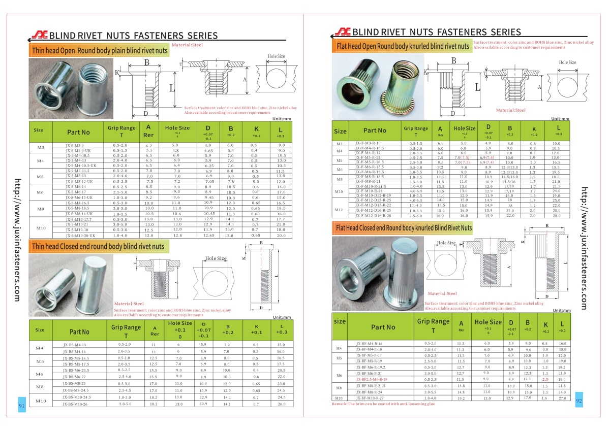
The existing JUXIN FASTENERS product information references detailed specification PDF pages 91–92 and related CAD documentation.
The applicable drawing should be reviewed to confirm individual dimensions, mounting hole tolerances, knurl geometry, body length, flange dimensions, and grip range.
OEM Technical RFQ Checklist
For accurate quotation and engineering review, please provide:
Required metric or Unified inch thread size
Panel material and thickness, in mm or inches
Mounting hole diameter and tolerance
Required grip range
Flange dimensions
Knurl geometry requirements, if specified
Mating screw size and tightening torque
Spin-out and pull-out performance requirements
Zinc coating and corrosion requirements
Approved drawing or CAD model
Inspection and documentation requirements
Sample quantity
Initial order quantity and annual demand forecast
JUXIN FASTENERS supports drawing-based sourcing inquiries for standard and custom industrial blind rivet nut requirements.
Why Choose Knurled Body Blind Rivet Nuts?
A conventional smooth-body rivet nut relies primarily on the installed deformation and contact with the mounting panel to resist rotation.
A knurled-body rivet nut incorporates surface features that can engage the surrounding material and provide additional resistance to turning.
This distinction can be important in assemblies involving repeated screw installation, maintenance access, or relatively high tightening torque.
However, knurling does not guarantee a particular spin-out torque. Actual performance depends on the knurl geometry, panel material,
hole tolerance, grip range, and installation conditions.
Typical Industrial Applications
Automotive and Transportation Components
Knurled steel rivet nuts may be considered for interior brackets, equipment covers, sheet metal housings, and non-critical fastening points requiring repeated screw assembly.
For vibration-exposed applications, verify the complete joint design and retention performance.
Electrical Enclosures and Control Cabinets
These threaded inserts can provide attachment points for removable panels, mounting brackets, and internal accessories.
Knurled-body engagement may be beneficial where repeated tightening could otherwise cause an installed insert to rotate.
Industrial Machinery and Equipment
Applications may include fabricated steel covers, equipment guards, brackets, access panels, and machine housings.
One-sided installation is particularly useful when the reverse side of the mounting material cannot be reached.
HVAC and Refrigeration Equipment
Potential uses include equipment housings, support brackets, access covers, and fabricated sheet metal components.
Material selection and corrosion protection should reflect the actual service environment.
Rail Vehicle Interior Equipment
Knurled rivet nuts may be considered for selected non-structural interior equipment and removable panels, subject to project-specific engineering approval.
Rail applications may require additional vibration, mechanical retention, material, and documentation requirements.
General Sheet Metal Fabrication
Knurled blind rivet nuts can be considered where thin material does not provide sufficient thread engagement
for direct tapping and conventional nut installation is impractical.
Knurled Versus Smooth Body Selection
Choose a knurled-body configuration when additional anti-rotation engagement may be beneficial.
A smooth-body configuration may be suitable when installation loads, panel material, and rotational retention requirements permit.
Neither design should be selected solely on appearance.
Engineering validation should consider the mounting hole, panel material, installation method, and required tightening torque.
OEM Engineering and Procurement Support
JUXIN FASTENERS supports drawing-based sourcing and industrial bulk purchasing requirements for knurled steel blind rivet nuts.
Engineering teams can submit installation drawings, panel thickness, hole tolerances, retention requirements, and mating screw specifications.
Purchasing managers and supplier development teams can provide approved drawings, order quantities,
annual demand forecasts, coating requirements, inspection specifications, and delivery requirements.
Request an OEM Quotation
For flat head knurled steel blind rivet nuts, custom threaded inserts, and industrial purchasing requirements, contact:
JUXIN FASTENERS
Email: info@juxinfasteners.com
Website: www.juxinfasteners.com
Contact: https://www.juxinfasteners.com/contact-us/
Please send your technical drawing, product specifications, and purchasing requirements for review and quotation.
Product Packaging
Packaging & OEM Ordering — Knurled Steel Blind Rivet Nuts
Standard Export Packaging
JUXIN FASTENERS provides industrial export packaging for knurled steel blind rivet nuts to support product protection, handling, storage, and international transportation.
The standard packaging arrangement includes protective inner plastic bags, outer cartons, and palletized shipment where required.
Reference Packaging Dimensions
| Packaging Type | Metric Dimensions | Approximate Inch Dimensions |
|---|---|---|
| Carton Option 1 | 29 × 19 × 19.5 cm | 11.42 × 7.48 × 7.68 in |
| Carton Option 2 | 23.5 × 17.5 × 8 cm | 9.25 × 6.89 × 3.15 in |
| Pallet Reference | 215 × 100 × 90 cm | 84.65 × 39.37 × 35.43 in |
These dimensions are reference packaging sizes. Actual carton quantities, dimensions, and pallet arrangements are confirmed according to product size and purchase order requirements.
Product Protection and Identification
Packaging arrangements may include:
Protective plastic inner bags
Reinforced export cartons
Moisture-resistant protection where required
Product identification labels
Part number and specification marking
Batch identification
Quantity labels
Palletized shipment where required
Packaging and identification requirements should be agreed before order confirmation.
Customized OEM Packaging
Customer-specific packaging options can be reviewed, including:
Private labeling
Customized barcode labels
Customer part-number identification
Specified carton dimensions
Customer-defined packing quantities
Special pallet configurations
Customer-specific marking and traceability requirements
Customized packaging may involve additional costs or lead times depending on the agreed requirements.
OEM and Industrial Bulk Purchasing
JUXIN FASTENERS supports purchasing inquiries from OEM manufacturers, strategic sourcing teams,
supplier development professionals, and industrial equipment manufacturers.
For quotation review, please provide:
Required thread size and product configuration
Approved technical drawing and revision
Material and coating requirements
Panel thickness and grip range
Installation and mechanical performance requirements
Inspection and documentation requirements
Packaging and labeling specifications
Initial order quantity
Annual demand forecast
Requested delivery schedule
Sample availability, minimum order quantity, pricing, production lead time, and ordering conditions are confirmed during quotation review.
Request an OEM Quotation
For knurled steel blind rivet nuts, custom threaded inserts, and industrial bulk purchasing requirements, contact:
JUXIN FASTENERS
Email: info@juxinfasteners.com
Website: www.juxinfasteners.com
Contact: https://www.juxinfasteners.com/contact-us/
Please send your technical drawing, specifications, and purchasing requirements for review and quotation.
Product Pictures
Tags
Contact Us
Tel.:
+86 020 8621 0320
+86 020 3121 6067
E-mail:
Technical Support:
Navigation
SEND INQUIREY