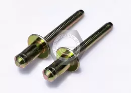
Call Us
+86 136 6007 9809
Call Us
+86 136 6007 9809

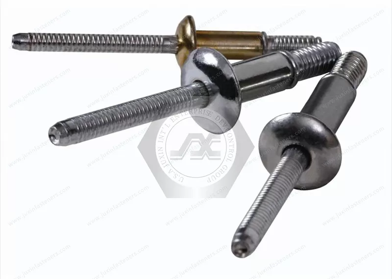
JUXIN FASTENERS supplies JX-THR1 wide-grip structural blind rivets in steel/steel and stainless steel/stainless steel configurations.
Designed for one-sided fastening across varying joint thicknesses, this structural bulbing rivet type uses shear-ring engagement, mandrel locking features,
and an enlarged blind-side bearing area. Suitable applications include truck bodies, trailers, industrial equipment, and fabricated assemblies requiring engineered joint retention.
Product Specification
Wide-Grip Double-Locking Structural Blind Rivets
JX-THR1 Series | Structural Bulbing Fasteners with Shear-Ring Engagement and Mechanical Core Pin Retention
JUXIN FASTENERS supplies JX-THR1 wide-grip structural blind rivets for OEM manufacturers, engineering teams, and industrial purchasing organizations seeking high-performance blind fastening solutions.
This structural fastener type combines a wide grip-range concept with blind-side bulbing, a shear-ring engagement mechanism, and positive mechanical core pin retention.
Its specialized setting principle is intended to accommodate variations in assembled material thickness while developing a controlled blind-side retaining structure.
The design is particularly relevant to industrial assemblies where one-sided access, joint clamp-up, shear resistance, and blind-side bearing support are important.
JUXIN identifies two material configurations for this product series:
Steel Body + Steel Mandrel
Stainless Steel Body + Stainless Steel Mandrel
Specific material grades, locking geometry, available sizes, grip ranges, mechanical ratings, and installation requirements must be confirmed against the approved JUXIN engineering drawings.
What Is a Wide-Grip Double-Locking Structural Blind Rivet?
A wide-grip double-locking structural blind rivet is a specialized pull-type fastener designed to secure joined components through an engineered sleeve-and-core-pin assembly.
Unlike general-purpose open-end blind rivets, this structural design incorporates additional features intended to control the setting process and retain the installed core pin.
The fastening concept includes:
A structural rivet sleeve
A specially configured mandrel or core pin
A shear-ring feature
Annular catch grooves on the mandrel
Blind-side sleeve expansion
Mechanical core pin retention
During installation, the mandrel is pulled through the sleeve.
The resulting deformation develops a blind-side retaining structure while the shear-ring and locking features control the relationship between the mandrel, sleeve, and joint thickness.
The complete installed geometry must be verified for the specific JX-THR1 configuration.
The Engineering Principle Behind Double-Locking
The term double-locking describes a structural fastening concept that secures the joint through coordinated mechanical engagement.
One part of the mechanism develops the blind-side retaining structure, while the core-pin locking arrangement provides additional retention within the installed rivet.
The purpose is to maintain joint integrity and reduce the risk of unwanted core-pin movement.
This differs from simply breaking a conventional rivet mandrel after the sleeve has expanded.
For engineering qualification, the locking sequence must be examined as part of the complete installed fastener.
Important considerations include:
Sleeve deformation
Blind-side bearing geometry
Shear-ring movement
Catch-groove engagement
Core-pin locking position
Final mandrel break location
Installed joint clamp-up
The double-locking designation should be supported by the approved JUXIN product geometry and qualification testing.
How the Shear Ring Works
The shear ring is an important element of this structural bulbing fastener concept.
As the installation tool pulls the mandrel, the sleeve begins to deform and the joint components are drawn together.
The shear-ring feature participates in the formation of the blind-side retaining structure.
At the intended stage of installation, the ring releases or moves according to the engineered design.
It can then engage a corresponding catch groove on the mandrel.
This controlled interaction helps establish the installed blind-side geometry across the specified grip range.
Controlled Expansion
The ring participates in directing the deformation of the sleeve.
Grip Accommodation
The relationship between the ring and mandrel grooves allows the fastening mechanism to respond to different approved joint thicknesses.
Blind-Side Support
The resulting expanded sleeve provides a bearing surface behind the assembly.
Joint Clamp-Up
The installed mechanism is intended to maintain the required contact between joined components.
Actual ring movement, engagement positions, and retained clamping force must be confirmed through the specific JX-THR1 design and testing.
Mandrel Catch Grooves and Annular Locking Features
The mandrel includes annular features associated with the shear-ring engagement mechanism.
These grooves are located on the core pin and serve a different purpose from the external grooves found on grooved-body blind rivets for wood or plastic.
In a structural double-locking design, the catch grooves provide defined engagement locations during installation.
Their geometry influences how the mechanism accommodates joint thickness and retains the expanded blind-side structure.
Engineering review should address:
Groove profile
Groove spacing
Mandrel diameter
Shear-ring compatibility
Engagement position
Mandrel material properties
Setting load
Final installed core position
These features are critical engineering dimensions and should be controlled through approved drawings.
Wide Grip Range: Accommodating Different Joint Thicknesses
Grip range is the total assembled material thickness that a fastener is designed to join.
A wide-grip structural blind rivet can accommodate a broader specified thickness interval than some conventional narrow-grip fasteners.
This is useful in manufacturing environments where component stack-ups vary.
Typical sources of variation include:
Different sheet metal gauges
Reinforcement plates
Fabricated brackets
Multiple-layer assemblies
Panel design changes
Manufacturing tolerances
Protective coatings
Benefits for Design Engineers
A wider approved grip range may allow a common fastener design to be used across multiple compatible assemblies.
Benefits for Production Managers
Reducing the number of fastener lengths may simplify line-side inventory and help reduce selection errors.
Benefits for Purchasing Teams
Fastener standardization may reduce the number of purchased part numbers and simplify demand planning.
However, each selected fastener must still be used within its approved minimum and maximum grip thickness.
A wide-grip designation does not establish an unlimited grip range.
Structural Bulbing and Blind-Side Bearing Area
The blind-side bulb is the expanded retaining structure formed behind the joined components.
Its geometry affects the distribution of contact pressure and the resistance of the joint to pull-through.
A larger bearing area may be useful when joining relatively thin or lower-strength materials.
Load Distribution
The expanded sleeve can distribute bearing forces across a larger region of the blind-side surface.
Pull-Through Resistance
An appropriately formed bulb can help reduce the risk of local fastener pull-through.
Thin Sheet Assemblies
The blind-side footprint may provide useful support where sheet thickness is limited.
Lightweight Materials
Selected plastics, composites, and lightweight panels may benefit from distributed bearing loads.
However, material compatibility must be evaluated.
A large blind-side bulb does not automatically make a fastener suitable for every plastic, composite, or thin sheet material.
The workpiece must tolerate the installation forces and service loads.
Positive Mechanical Core Pin Retention
Mechanical core pin retention is an important feature of many structural blind fastening systems.
After installation, the retained portion of the mandrel is secured within the rivet sleeve through a designed mechanical locking arrangement.
This differs from relying only on frictional retention.
Core Pin Security
The locking mechanism is intended to reduce unwanted movement or release of the retained pin.
Structural Load Transfer
Depending on the design, the retained core may contribute to the fastener's mechanical performance.
Vibration Considerations
Mechanical pin retention can be relevant to applications exposed to vibration or repeated loading.
Installation Verification
The final core-pin position should be checked against the approved acceptance criteria.
For certain structural rivet designs, a near-flush or flush core-pin position is used as a visual inspection indicator.
For JX-THR1, the permitted installed pin position and inspection tolerance must be established from the approved drawing.
Visual appearance alone should not replace the required installation qualification.
Clamp-Up Force and Gap Closing
Clamp-up is the force that brings the joined components together during installation.
Structural blind rivets may be selected where the joint requires controlled pull-up and component contact.
The final clamping condition depends on the interaction between the fastener and the assembly.
Important factors include:
Joint stiffness
Initial component gaps
Total grip thickness
Rivet geometry
Mandrel pulling load
Shear-ring engagement
Blind-side deformation
Installation tool performance
Gap Closing Capability
The setting process may help draw compatible components together.
Joint Stability
Adequate clamp-up can help limit unwanted relative movement between joined components.
Assembly Consistency
A controlled installation process supports repeatable fastening quality.
The required clamp-up performance must be verified for the actual joint.
The fastener should not be used to compensate for excessive assembly misalignment or unacceptable component gaps.
Steel and Stainless Steel Material Configurations
Steel Body with Steel Mandrel
The steel/steel configuration is relevant to industrial applications where strength, installation performance, and cost must be balanced.
The actual steel grades and surface treatment should be selected according to the mechanical and environmental requirements.
Stainless Steel Body with Stainless Steel Mandrel
The stainless steel/stainless steel configuration may be considered where corrosion resistance is an important design requirement.
The specific stainless steel grades and their mechanical properties must be verified.
Material Selection Considerations
Engineering teams should compare:
Required shear strength
Required tensile strength
Installation force
Core-pin locking performance
Corrosion environment
Galvanic compatibility
Temperature exposure
Expected service life
Procurement cost
The steel and stainless steel configurations should not be assumed to have identical strength ratings, grip ranges, or setting requirements.
Structural Blind Rivets Versus Conventional Blind Rivets
Conventional blind rivets are widely used for general-purpose sheet metal assembly.
They typically rely on deformation of the rivet body to form a blind-side closing head.
Structural blind rivets are engineered for applications requiring additional attention to load capacity, retained mandrel behavior, and installed joint integrity.
A wide-grip double-locking structural blind rivet adds a specialized shear-ring and locking concept.
This may provide advantages in appropriate applications involving variable material thickness, blind-side bearing requirements, and controlled core-pin retention.
However, different structural blind rivet families use different mechanisms.
They should not be substituted solely because they have similar external appearances.
Hole Size and Joint Geometry
Correct installation hole preparation is essential.
Hole Diameter
The hole must match the approved rivet specification.
Oversized holes may reduce installation consistency and affect load transfer.
Grip Thickness
The total thickness of the joined components must fall within the approved range.
Hole Alignment
Misaligned holes can interfere with insertion and proper setting.
Blind-Side Clearance
The assembly must provide sufficient space for the expanded bulb.
Edge Distance
The material surrounding the hole must provide adequate support against tearing or pull-through.
Head Seating
The accessible-side head must contact the workpiece as intended.
Workpiece Strength
The joined materials must be capable of supporting the installation and service loads.
Installation dimensions should be obtained from the applicable JUXIN drawing rather than from unrelated fastener specifications.
Installation Sequence
The following sequence describes the general setting principle of this structural blind fastener type.
Fastener Selection
Confirm the material, diameter, head style, and approved grip range.
Joint Preparation
Prepare and inspect the installation holes.
Check component alignment and blind-side clearance.
Rivet Insertion
Insert the structural blind rivet through the aligned holes.
Seat the head against the accessible surface.
Tool Engagement
Position the approved installation tool and nose assembly over the mandrel.
Initial Pulling
Activate the tool to pull the mandrel and begin sleeve deformation.
Blind-Side Formation
The sleeve expands behind the workpiece and develops the retaining structure.
Shear-Ring Engagement
The shear-ring feature interacts with the mandrel grooves according to the engineered mechanism.
Core Pin Locking
The retained core is secured through the specified locking arrangement.
Mandrel Separation
The excess mandrel separates at the designed break location.
Final Inspection
Verify head seating, installed pin position, and other product-specific acceptance criteria.
The exact setting sequence and inspection requirements must be confirmed for JX-THR1.
Installation Quality Control for OEM Production
Structural blind riveting requires controlled installation processes.
For production managers, important quality controls include:
Incoming fastener identification
Material and finish verification
Grip thickness measurement
Hole diameter inspection
Installation tool compatibility
Nose assembly condition
Tool maintenance
Setting stroke or force monitoring, where applicable
Core-pin position inspection
Blind-side formation verification
Representative mechanical testing
Production traceability
Where direct blind-side inspection is impractical, process validation and sample destructive testing may be appropriate.
Common Installation Failure Modes
Incomplete Blind-Side Formation
Insufficient setting movement may prevent the intended bulb from forming.
Incorrect Shear-Ring Engagement
A malfunction in the ring or catch-groove interaction may affect the final installed condition.
Improper Core Pin Retention
Failure to achieve the required locking position may reduce joint reliability.
Incorrect Grip Range
A rivet installed outside its specified thickness range may not develop the intended geometry.
Oversized Installation Holes
Excessive hole clearance may affect joint performance.
Insufficient Blind-Side Clearance
Nearby structures may obstruct bulb formation.
Workpiece Pull-Through
Thin or weak materials may fail locally under loading.
Tooling Problems
Incorrect or worn nose assemblies may cause incomplete or inconsistent setting.
These conditions should be evaluated using the approved installation specification and representative testing.
Shear Strength and Tensile Strength
Structural blind rivets are commonly evaluated for shear and tensile performance.
Shear Loading
Shear loads act across the joined components.
The fastener's sleeve, retained core, and installed geometry influence the resulting resistance.
Tensile Loading
Tensile loads tend to separate the joined components along the fastener axis.
The head, blind-side retaining structure, and material strength contribute to the joint's resistance.
Combined Loading
Some assemblies experience shear and tensile loads simultaneously.
Fatigue Loading
Repeated loads can affect both the fastener and the surrounding workpiece.
Vibration Exposure
Mechanical locking and joint clamp-up must be evaluated under representative service conditions.
Pull-Through
The workpiece material may fail locally even when the fastener itself remains intact.
Numerical mechanical ratings must be based on verified JUXIN testing or approved technical documentation.
Commercial Vehicle and Truck Body Applications
Commercial vehicle assemblies frequently involve fabricated metal components, panels, brackets, and reinforcement structures.
Potential applications for qualified structural blind rivets include:
Truck body panel assemblies
Fabricated brackets
Reinforcement components
Equipment mounting structures
Selected vehicle body attachments
Designers should evaluate vibration, fatigue, corrosion, and joint loading.
Safety-critical applications require appropriate engineering qualification.
Trailer Manufacturing and Transport Equipment
Trailer assemblies may involve multiple material thicknesses and limited access to the reverse side of a joint.
Wide-grip structural blind rivets may be evaluated for:
Fabricated trailer panels
Selected body attachments
Metal reinforcement assemblies
Equipment enclosures
Bracket installations
The selected rivet must meet the application's mechanical and environmental requirements.
HVAC Equipment and Industrial Enclosures
HVAC and industrial equipment manufacturers often work with fabricated sheet metal assemblies.
Potential applications include:
Equipment housing components
Reinforcement brackets
Panel assemblies
Fabricated structural supports
Mechanical enclosure attachments
The required fastener performance should be established from the equipment design.
Electrical Equipment and Power Infrastructure
Selected electrical equipment assemblies may require one-sided mechanical fastening.
Possible applications include:
Fabricated cabinet structures
Mechanical enclosure components
Equipment support brackets
Industrial panel assemblies
Electrical continuity, grounding, and bonding performance must be evaluated separately when required.
Data Center and Industrial Equipment Structures
Structural blind riveting may be considered for suitable fabricated equipment assemblies involving limited rear access.
Potential applications include:
Equipment cabinet frames
Fabricated support brackets
Mechanical enclosure structures
Equipment mounting assemblies
The use of structural blind rivets does not by itself establish compliance with equipment safety or structural requirements.
Lightweight Panels, Plastics and Composites
The enlarged blind-side bearing area of a structural bulbing fastener may be beneficial in certain lightweight assemblies.
However, the fastener must be evaluated against the specific material.
Important concerns include:
Local bearing stress
Panel crushing
Plastic creep
Composite delamination
Hole damage
Thermal expansion differences
Fatigue loading
Representative installation and joint testing are recommended before production approval.
Production Efficiency and Fastener Standardization
A wide-grip structural blind rivet may allow manufacturers to reduce the number of different fastener lengths used across compatible assemblies.
Potential operational benefits include:
Simplified part selection
Reduced line-side inventory
Fewer fastener changeovers
One-sided assembly access
Consistent installation procedures
Reduced risk of incorrect length selection
Actual efficiency improvements depend on the approved grip ranges, equipment, assembly conditions, and quality controls.
OEM Procurement and Supplier Qualification
Purchasing managers and sourcing engineers should evaluate the product as an engineered fastening system rather than a generic blind rivet.
A complete technical RFQ should identify:
JX-THR1 series or approved drawing reference
Body diameter
Body length
Head style
Steel or stainless steel material grades
Mandrel material
Surface finish
Minimum grip thickness
Maximum grip thickness
Installation hole diameter
Shear strength requirement
Tensile strength requirement
Core-pin retention requirement
Blind-side clearance
Installation tooling
Inspection requirements
Packaging and labeling
Order quantity
Estimated annual demand
For projects involving specific double-locking or shear-ring geometry, detailed drawings and performance requirements should be included.
Custom Wide-Grip Structural Blind Rivets
JUXIN FASTENERS welcomes OEM drawing-based inquiries for structural blind rivets and related engineered fastening components.
Potential custom requirements may include:
Body diameter and length
Head dimensions
Grip range
Mandrel geometry
Shear-ring configuration
Mechanical locking features
Steel or stainless steel material specifications
Surface treatments
Packaging requirements
Manufacturing feasibility, dimensional requirements, and mechanical qualification must be reviewed before order confirmation.
Metric and Inch Dimension References
Structural blind rivets are commonly described in both metric and inch-based industrial markets.
For engineering reference:
3/16 inch is approximately 4.76 mm.
1/4 inch is approximately 6.35 mm.
These are general dimensional references and do not establish JUXIN available sizes.
Metric and inch-designated fasteners must not be considered interchangeable without verifying actual body diameter, hole size, grip range, head geometry, and installation requirements.
Only confirmed JUXIN dimensions should be published as available product specifications.
Technical Drawings and Engineering Documentation
The approved JUXIN product drawing should define:
Rivet body dimensions
Head geometry
Mandrel dimensions
Shear-ring geometry
Catch-groove configuration
Mechanical locking features
Material specifications
Surface finish
Grip range
Installation hole size
Tool compatibility
Mechanical performance
Final core-pin position
Installation acceptance criteria
Where required, OEM qualification should include installation trials, dimensional inspection, and representative mechanical testing.
Frequently Asked Questions
What is a wide-grip double-locking structural blind rivet?
It is a specialized structural blind fastener designed to accommodate a defined range of joint thicknesses using an engineered blind-side expansion and mechanical locking arrangement.
What is the purpose of the shear ring?
The shear ring participates in the setting mechanism and may engage mandrel catch grooves to control blind-side formation across the approved grip range.
What are mandrel catch grooves?
They are annular engagement features on the mandrel used in the structural locking mechanism.
Are these the same as grooved blind rivets for wood?
No. The annular grooves in this structural design are associated with the mandrel locking mechanism.
Grooved-body blind rivets for wood use external sleeve grooves to engage the receiving substrate.
Why is a large blind-side bulb important?
It provides a larger bearing area that may help distribute load and reduce pull-through risk in compatible materials.
What does positive mechanical core pin retention mean?
It describes a designed mechanical arrangement that secures the retained core pin within the installed fastener.
Can one wide-grip rivet replace several conventional rivet lengths?
Potentially, yes, if all relevant joint thicknesses fall within the fastener's verified grip range and the application requirements are satisfied.
Are steel and stainless steel versions interchangeable?
Not automatically. Mechanical properties, corrosion behavior, and installation requirements must be evaluated separately.
Can these rivets be used in truck and trailer manufacturing?
They may be evaluated for suitable fabricated vehicle assemblies, subject to engineering qualification.
Does a flush core pin confirm successful installation?
It can be a visual indicator for certain structural fastener designs. The approved JUXIN installation criteria must establish the acceptable final pin position.
Can JUXIN manufacture custom structural blind rivets?
JUXIN welcomes OEM drawing-based inquiries for custom configurations, subject to engineering review and manufacturing feasibility.
Request an OEM Quotation — Wide-Grip Double-Locking Structural Blind Rivets
JUXIN FASTENERS supports global OEM manufacturers, Tier-1 and Tier-2 suppliers, structural engineers,
design engineers, production managers, purchasing managers, sourcing specialists, and supply chain teams.
For an accurate quotation, please provide the fastener drawing, material specifications, required diameter, head style, grip range,
installation hole dimensions, mechanical performance requirements, installation equipment details, and estimated production quantity.
Please include 2D engineering drawings, 3D CAD models, or assembly drawings where available.
Email: info@juxinfasteners.com
Website: www.juxinfasteners.com
JUXIN FASTENERS — Industrial Fasteners and Custom OEM Fastening Solutions
Product Packaging
Packaging Standard
At Juxin Fasteners, we apply standardized export packaging to ensure product protection, traceability, and compliance with international logistics requirements.
1. Standard Export Packaging
Unless otherwise specified, all products will be packed according to our factory standard export packaging, which includes:
Moisture-resistant inner protection
Poly bag or small box packing as required
Reinforced export cartons
Clear labeling with part number, specification, batch number, and quantity
Palletizing for sea or air shipment when necessary
Our standard packaging is designed to ensure safe transportation, efficient warehousing, and long-distance international shipping.
2. Customized Packaging Options
We also provide customized packaging solutions according to customer requirements, including but not limited to:
Private labeling
Customized barcodes
Specific carton dimensions
Retail packaging
Special pallet configuration
Customer-specific marking and identification
So that you know, customized packaging may involve additional costs and extended lead time depending on the complexity of the requirements.
3. Compliance & Quality Assurance
All packaging processes are controlled under our ISO 9001 quality management system to ensure consistency, traceability, and product integrity throughout the supply chain.
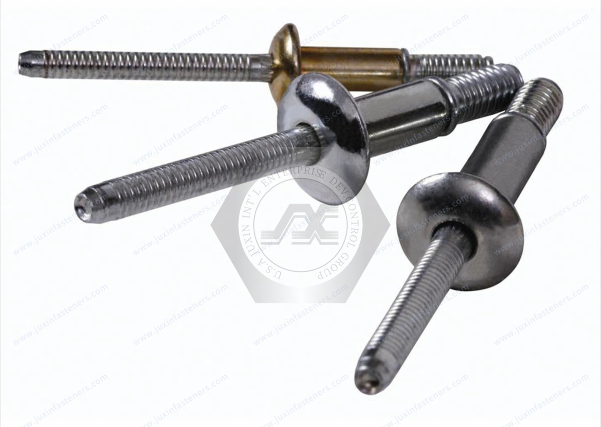
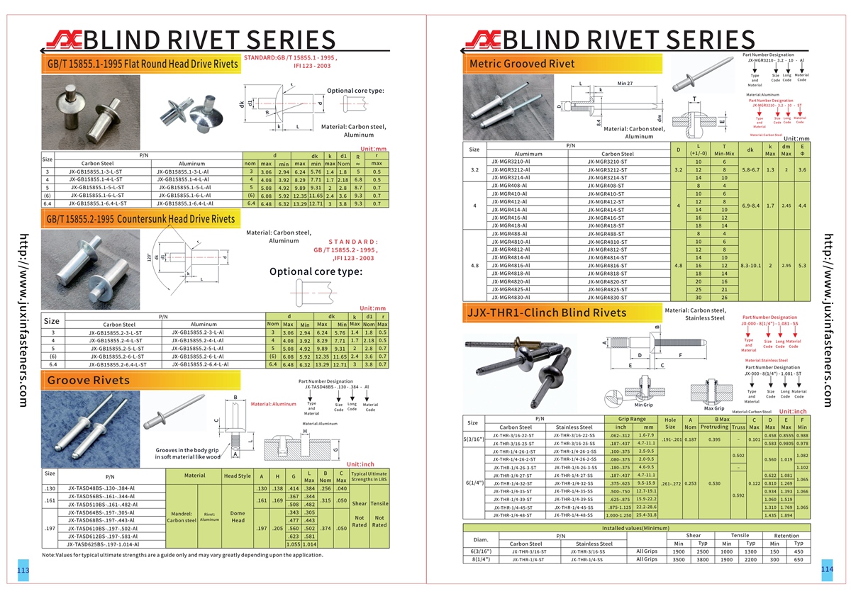
Product Pictures
Contact Us
Tel.:
+86 020 8621 0320
+86 020 3121 6067
E-mail:
Technical Support:
Navigation
SEND INQUIREY