Call Us
+86 136 6007 9809
Call Us
+86 136 6007 9809

How do engineers measure the structural integrity of welded fasteners under axial loads?
Fastener push-out and pull-out testing evaluates the mechanical behavior of resistance-welded fasteners when axial forces act approximately perpendicular to the parent sheet metal substrate.
Pull-out testing generally evaluates the force required to separate a weld fastener from the sheet in a tensile direction.
Push-out testing evaluates the resistance of the fastener and welded interface when the applied force drives the fastener toward or through the parent panel.
Product Specification
How do engineers measure the structural integrity of welded fasteners under axial loads?
Fastener push-out and pull-out testing evaluates the mechanical behavior of resistance-welded fasteners when axial forces act approximately perpendicular to the parent sheet metal substrate.
Pull-out testing generally evaluates the force required to separate a weld fastener from the sheet in a tensile direction.
Push-out testing evaluates the resistance of the fastener and welded interface when the applied force drives the fastener toward or through the parent panel.
The purpose is not simply to obtain a single “strength number.” A properly designed test helps engineers determine which part of the joint fails first,
how the parent sheet participates in the load path, and whether the weld interface or surrounding material governs joint capacity.
This distinction is important because the mechanical strength of a weld nut or weld stud as an individual component does not automatically represent the strength of the finished sheet-metal assembly.
A typical axial validation concept can be represented as:
             Axial Pull-Out Force
                    ↑
                    │
              [ Weld Fastener ]
                    │
            [ Weld Interface ]
                    │
        [ Parent Sheet / Panel ]
                    │
             [ Test Fixture ]


             Axial Push-Out Force
                    ↓
              [ Weld Fastener ]
                    │
            [ Weld Interface ]
                    │
        [ Parent Sheet / Panel ]
                    │
             [ Test Fixture ]
The actual failure path can involve several mechanisms:
separation at the weld interface
fracture or insufficient fusion around the weld projections
deformation of the parent sheet
tearing of the sheet around the welded area
button or plug-type failure of the parent material
local buckling or panel deformation
fastener deformation
thread stripping before the welded interface fails
fixture-induced failure or unintended load eccentricity
For this reason, push-out and pull-out testing should be treated as joint-level validation rather than a simple fastener tensile-strength test.
For OEM programs, the appropriate test method, specimen configuration, loading direction, acceptance criteria, sample quantity,
and reporting format should be established from the engineering drawing, customer specification, applicable test standard, and actual application requirements.
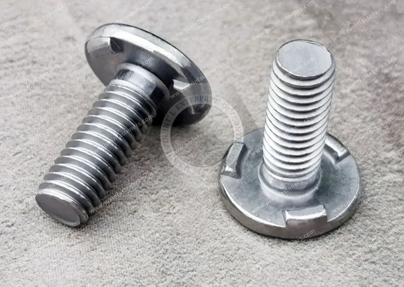
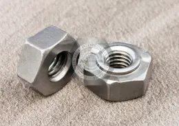
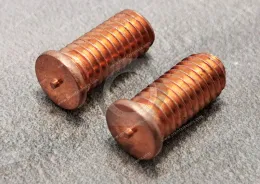
JUXIN FASTENERS supplies weld nuts, weld studs, and other engineered fastening components for sheet-metal applications where joint design,
welding compatibility, mechanical performance, and production validation must be considered together.
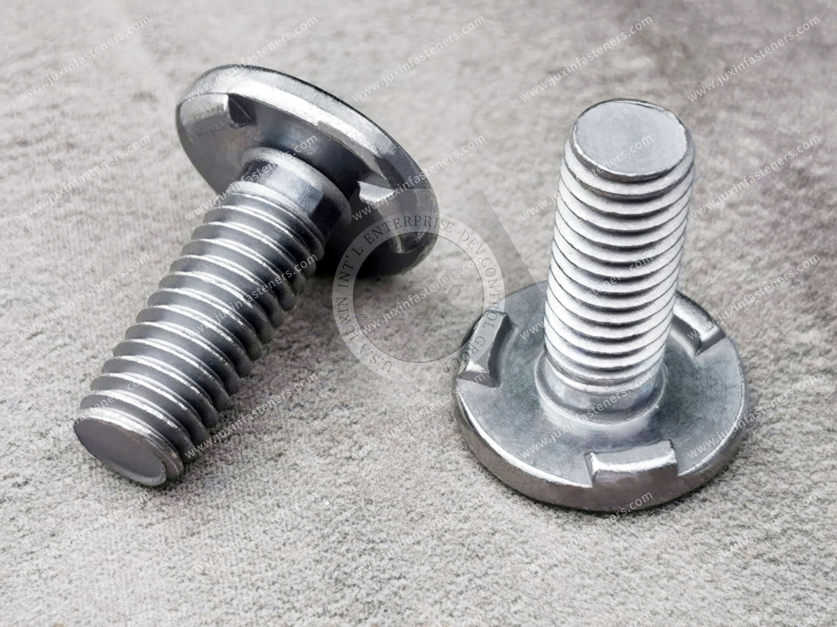
Product catalogs often provide nominal dimensions, materials, and mechanical properties.
However, the behavior of a welded fastener after installation depends on the interaction between the fastener, weld interface, parent sheet, welding process, and applied load.
This is one of the most important distinctions between component specification and assembly validation.
A weld fastener may have adequate material strength while the finished joint still fails because:
the weld nugget is incomplete
the projections do not collapse consistently
heat distribution is unbalanced
the parent sheet is too flexible for the selected configuration
the local sheet geometry creates excessive deformation
the applied load is eccentric
the weld interface is contaminated or otherwise inconsistent
the actual welding process differs from the validated process
the fastener geometry is unsuitable for the sheet and application
the thread fails before the welded joint reaches its intended structural capacity
Pull-Out — Tensile Separation
Pull-out testing applies an axial tensile load intended to separate the fastener from the parent sheet.
Depending on the joint design and materials, failure may occur through:
separation at the weld interface
fracture around the welded projections
tearing of the parent sheet
button or plug-type sheet failure
local sheet deformation followed by rupture
fastener deformation
thread-related failure if the test load is transferred through the threaded connection
A pull-out result therefore needs to be interpreted together with the observed failure mode.
A higher measured force is not automatically evidence of a better production design if the test fixture, specimen geometry, or loading condition does not represent the actual joint.
Push-Out — Compressive Dislodgment
Push-out testing applies force in the opposite axial direction, attempting to drive the fastener through or into the parent sheet.
This condition can be particularly relevant where a weld nut or similar fastener is installed into a panel or box-section assembly and later experiences an inward-directed service or assembly load.
Push-out behavior can differ substantially from pull-out behavior because:
the direction of force changes the local stress distribution
sheet deformation may dominate the response
flange or projection geometry may interact differently with the panel
the surrounding panel may provide different restraint
the fixture boundary conditions can strongly influence the measured result
Therefore, push-out and pull-out results should not automatically be treated as interchangeable values.
A useful engineering model is to consider the joint as a chain of load-transfer elements:
Applied Load
     ↓
Thread / Fastener
     ↓
Fastener Geometry
     ↓
Weld Interface
     ↓
Parent Sheet
     ↓
Panel Structure
     ↓
Fixture / Adjacent Structure
The weakest relevant section of this load path can determine the observed failure mode.
This means that improving one element of the system does not necessarily increase overall joint capacity.
For example, increasing fastener material strength may have limited benefit if the surrounding sheet tears first. Conversely, a stronger parent sheet does not solve an inadequately formed weld interface.
This weakest-load-path principle is one of the most useful concepts when interpreting push-out and pull-out test results.
Parent sheet thickness has an important influence on axial joint behavior, but thickness should not be evaluated in isolation.
Relevant variables include:
sheet thickness
yield and tensile properties
material grade
local hardness and material condition
fastener geometry
weld projection configuration
weld interface area
panel curvature
local reinforcement
hole or opening geometry where applicable
distance to edges or adjacent features
fixture restraint
applied load direction
For example, an increase in sheet thickness may improve resistance to local deformation in one design, but the resulting thermal mass and welding conditions may also change the weld process.
Similarly, higher-strength sheet materials can change the failure mode without necessarily producing a proportional increase in the overall joint capacity.
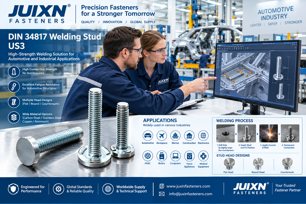
For resistance projection-welded fasteners, the weld interface is a critical part of the axial load path.
The welding process is influenced by variables including:
welding current
electrical resistance
electrode force
weld time
squeeze time
hold time
projection geometry
electrode alignment
surface condition
material combination
sheet thickness
fixture configuration
The familiar resistance-heating relationship:
Q ∝ I²Rt
helps explain why current, resistance, and time influence heat generation, but this relationship should not be interpreted as a universal recipe for weld parameter selection.
Actual welding parameters must be developed and validated for the specific fastener, substrate, tooling, equipment, and production process.
An inadequate or inconsistent weld interface can produce a joint that appears visually acceptable but has insufficient resistance to axial separation.
A common mistake is to treat the maximum force from a pull-out test as the only important result.
For engineering validation, the test report should ideally capture more than the peak load.
Depending on the customer specification and test objective, useful information can include:
maximum applied force
displacement at relevant points
force-displacement behavior
failure location
failure mode
specimen condition
fastener configuration
parent sheet material
parent sheet thickness
welding process information
fixture configuration
test orientation
sample identification
environmental condition where relevant
test equipment and calibration status
acceptance criteria
photographs of failed specimens
The purpose is to answer a more valuable engineering question:
Did the joint fail in the intended load path, and did it meet the required performance under the specified test condition?
There is no single pull-out or push-out value that can safely be applied to every weld fastener application.
A measured result depends on the complete test configuration.
Two assemblies using the same weld nut may produce different results because the parent sheets have different:
thicknesses
material grades
yield strengths
surface conditions
panel geometries
edge conditions
reinforcement structures
The weld equipment and process can also change the result.
Therefore, engineering acceptance values should come from the applicable product specification, customer drawing, internal design requirement,
validation plan, or recognized test procedure rather than from a generic internet benchmark.
Push-out and pull-out testing is often destructive.
This creates an important distinction between:
Validation testing
Used to establish whether a new design, material combination, welding process, or production setup meets the required mechanical performance.
and
Production quality control
Used to monitor whether manufacturing remains consistent with the validated process.
Production monitoring may include dimensional inspection, welding-process monitoring, sample destructive testing, visual inspection, and other controls appropriate to the application.
A supplier should therefore be able to explain not only what the initial test result was, but also how production consistency is controlled afterward.
One of the most underestimated factors in mechanical testing is fixture design.
A poorly designed fixture can introduce:
unintended bending
eccentric loading
panel deformation unrelated to the application
excessive local restraint
premature fixture failure
incorrect force transfer
artificial strengthening or weakening of the specimen
For this reason, a test fixture should reproduce the relevant boundary conditions of the intended joint as closely as practical.
The intended load direction should be clearly defined.
If the application experiences primarily axial loading but the test fixture introduces a significant bending component, the measured result may not represent the actual design condition.
Similarly, if the production assembly contains surrounding structure that restrains the panel, testing an isolated flat coupon may produce a different failure mechanism.
The fixture should be sufficiently rigid for the intended test so that fixture deformation does not dominate the measured response.
However, “maximum stiffness” is not automatically the objective.
The fixture should provide controlled and repeatable boundary conditions that correspond to the engineering question being investigated.
A flat-sheet coupon is useful for process development and comparative testing.
A representative production assembly can be more appropriate when:
panel geometry strongly affects stiffness
surrounding structure constrains deformation
multiple fasteners share load
local reinforcements affect load transfer
the fastener is installed near formed features
the actual assembly has complex boundary conditions
The appropriate test specimen therefore depends on the validation objective.
The maximum force tells engineers when the specimen reached a defined maximum load.
Failure analysis helps explain why it failed.
If the fastener separates through the weld interface, engineers should investigate:
projection geometry
weld current
electrode force
weld time
surface contamination
electrode alignment
electrical contact
fastener positioning
substrate compatibility
welding equipment condition
If a portion of the parent sheet tears away with the fastener, the weld may not be the weakest part of the joint.
This type of failure can indicate that the welded interface is transferring substantial load into the sheet, while the surrounding sheet structure governs final capacity.
This is why a “failed weld” should not automatically be diagnosed simply because the fastener separated from the panel.
Thin or flexible sheet structures may deform significantly before complete separation.
The measured maximum force may therefore depend on how the test fixture restrains the surrounding panel.
For engineering applications, deformation behavior may be as important as the final peak force.
The welded joint can remain intact while the threaded connection fails.
Potential mechanisms include:
thread stripping
bolt failure
nut thread deformation
incorrect mating fastener
excessive tightening
unsuitable thread specification
This creates an important diagnostic distinction:
A thread failure is not the same as a weld-interface failure.
The correct corrective action depends on the actual failure location.
Fastener push-out and pull-out testing represents two closely connected search intents.
Engineers typically need answers to questions such as:
How should a weld nut be tested for axial strength?
What causes weld fastener pull-out?
How does sheet thickness affect pull-out resistance?
Why did the parent sheet tear before the weld failed?
How should a pull-out test fixture be designed?
What failure modes should be recorded?
How should weld fastener validation be documented?
Which test conditions represent the production assembly?
These searches require engineering explanation rather than a product catalog.
Procurement and supplier-development teams often search from a risk-management perspective:
Can the supplier provide mechanical validation?
Can the supplier support customer-specific test requirements?
Can the supplier provide dimensional and material documentation?
How is weld fastener quality controlled?
Can the supplier support prototype and production validation?
Can the supplier manufacture according to engineering drawings?
Can the supplier investigate failed samples?
Can the supplier support global OEM sourcing requirements?
A strong B2B product solution should address both sides of this decision.
Automotive applications can involve demanding axial loads, vibration, impact conditions, thermal cycling, and strict process-control requirements.
Potential applications for weld fasteners include:
body-in-white structures
brackets
seat-related structures
chassis components
underbody assemblies
battery enclosure components
powertrain-related brackets
electrical and electronic mounting structures
However, the required validation criteria depend on the exact component, customer specification, material system, and load case.
A weld nut that performs adequately on a simple panel coupon should not automatically be considered qualified for a safety-critical vehicle structure.
For automotive programs, validation may need to consider:
static axial loading
shear loading
combined loading
vibration
fatigue
corrosion exposure
thermal cycling
manufacturing-process variation
coating compatibility
production welding repeatability
Construction equipment, agricultural machinery, industrial vehicles, and heavy machinery can subject welded fasteners to:
shock loading
vibration
cyclic loading
bracket loads
structural movement
environmental exposure
repeated service maintenance
Potential applications include:
equipment brackets
hydraulic-system supports
electrical enclosures
operator-cab components
chassis accessories
protective guards
mounting brackets
service-access panels
For these applications, joint validation should consider not only peak axial force but also the real load path and repeated service conditions.
Weld fasteners are widely useful in sheet-metal electrical and industrial assemblies where threaded mounting points are needed without adding separate loose nuts.
Applications can include:
electrical cabinets
control panels
industrial enclosures
power equipment
transformer-related structures
machinery housings
mounting brackets
grounding or bonding hardware where the complete electrical interface is appropriately designed
Push-out and pull-out testing can help evaluate whether the fastener remains mechanically anchored when equipment-mounted components impose axial loads on the enclosure panel.
For electrical bonding applications, mechanical retention and electrical continuity should be treated as separate validation requirements.
Mechanical testing should begin during design rather than only after a failed production trial.
The correct weld nut or weld stud depends on:
thread size
fastener geometry
sheet material
sheet thickness
expected load direction
installation access
welding equipment
surrounding geometry
coating requirements
environmental conditions
The largest or strongest-looking fastener is not automatically the most appropriate solution.
The parent sheet is part of the joint.
Design engineers should evaluate:
local sheet deformation
edge conditions
formed features
panel curvature
reinforcement
adjacent holes
surrounding welds
accessibility for electrodes
expected assembly loads
A fastener design must also be compatible with the available welding process.
The engineering review should consider:
electrode access
electrode geometry
weld projection configuration
current path
electrode force
fixture arrangement
surface condition
production sequence
A fastener that is theoretically suitable but difficult to weld consistently may create a greater production risk than a slightly different design with a more robust process window.
A reliable weld fastener program requires controls before, during, and after welding.
Depending on the project requirements, incoming inspection can include:
dimensions
thread characteristics
material verification
projection geometry
surface condition
coating condition
visual inspection
Relevant process controls may include:
welding current monitoring
electrode force monitoring
weld time control
equipment maintenance
electrode condition
fixture condition
process parameter control
sample destructive testing where specified
The exact control plan should be based on the customer's quality requirements and the risk level of the application.
Mechanical testing can be incorporated at several stages:
Prototype
Used to compare design concepts and establish an initial process.
Pilot Production
Used to verify that the selected production equipment and process can reproduce the intended performance.
Production Validation
Used to confirm that ongoing production remains within the agreed quality requirements.
This staged approach is more informative than relying on one isolated laboratory result.
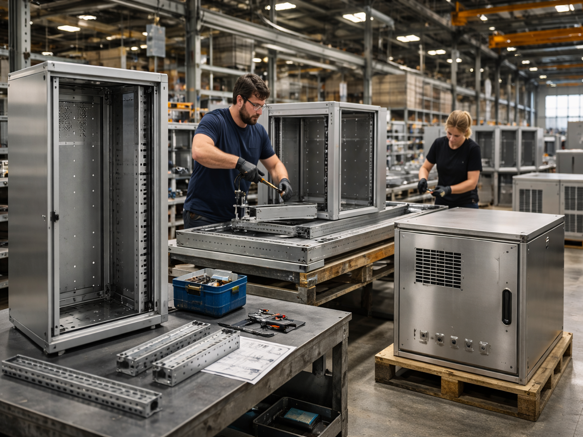
Push-out and pull-out testing should not be considered the only possible mechanical validation.
Depending on the application, engineers may also need to evaluate:
torque-out resistance
push-out resistance
tensile behavior
shear behavior
combined loading
fatigue
vibration
thermal cycling
corrosion exposure
dimensional stability
thread performance
The appropriate test portfolio should be driven by the actual failure risks of the application.
For example, a weld nut installed in an automotive panel may require different validation from a weld stud used to mount a heavy industrial bracket.
Mechanical testing should be performed according to the applicable customer specification, product standard, internal engineering procedure, or recognized test method.
International standards such as ISO, ASTM, DIN, EN, SAE, ASME, and related industry specifications may provide relevant frameworks depending on the application.
However, a standard should not be cited merely to make a product page appear technically authoritative.
The engineering team should identify:
which standard applies
which revision is required
which specimen configuration is specified
which loading direction is required
which acceptance criteria apply
how failures are classified
how results are documented
A test performed according to a recognized method is not automatically equivalent to qualification for every customer application.
Customer-specific requirements remain important.
For procurement and supplier-development teams, mechanical validation is only one part of supplier qualification.
An RFQ or supplier qualification package may include:
2D engineering drawing
3D CAD model where applicable
fastener material
thread specification
parent sheet material
parent sheet thickness
welding process
expected load direction
target application
required validation tests
applicable standards
coating requirements
dimensional requirements
annual usage
prototype quantity
production volume
packaging requirements
quality documentation
change-control requirements
The more complete the technical package, the less likely the quotation process is to compare technically different products as if they were equivalent.
A mechanical testing requirement often indicates a much larger commercial opportunity.
When an engineering team searches for:
“fastener push-out pull-out testing”
the underlying commercial need may actually be:
“We need a weld fastener supplier capable of helping us validate a complete sheet-metal joint.”
This creates a natural commercial conversion path:
Engineering Problem
        ↓
Fastener Selection
        ↓
Parent Sheet / Material Review
        ↓
Welding Process Review
        ↓
Prototype Samples
        ↓
Mechanical Validation
        ↓
Failure Analysis
        ↓
Design / Process Optimization
        ↓
Production Approval
        ↓
OEM Supply Program
This is why a technically strong fastener supplier should be evaluated not only on piece price, but also on its ability to participate in engineering development and quality communication.
The lowest unit price is not necessarily the lowest procurement cost.
A weld fastener failure can create costs associated with:
assembly disruption
rework
scrap
line stoppage
field service
warranty claims
engineering investigation
supplier corrective action
production delays
customer qualification delays
Early mechanical validation can help identify weak joint designs before they become production problems.
For procurement teams, this means joint validation should be viewed as a supply-chain risk-control activity, not simply a laboratory expense.
| Observed Failure | Possible Engineering Cause | Investigation Direction |
|---|---|---|
| Weld interface separates | Inadequate or inconsistent weld formation | Review welding process, projections, surface condition and tooling |
| Parent sheet tears | Sheet becomes the governing failure path | Review sheet material, thickness, local geometry and load distribution |
| Fastener deforms | Fastener geometry or material may be unsuitable | Review fastener specification and load path |
| Thread strips | Thread or mating connection governs failure | Review thread specification, mating hardware and assembly load |
| Large panel deformation | Local sheet stiffness is insufficient | Review panel geometry, reinforcement and fixture conditions |
| Results vary significantly | Process or specimen variation | Review welding parameters, tooling, material and test setup |
| Unexpected bending failure | Eccentric loading or fixture effect | Review alignment and boundary conditions |
| Different results between coupons and assembly | Boundary conditions differ | Test a more representative production configuration |
The objective of failure analysis is not merely to label the sample as “pass” or “fail.”
The objective is to determine which engineering variable should change next.
A practical workflow can be structured as follows:
Identify whether the joint experiences:
tensile loading
compressive loading
shear loading
combined loading
static loading
cyclic loading
Document:
fastener type
thread
material
sheet material
sheet thickness
panel geometry
welding configuration
Determine whether the concern is:
weld separation
parent sheet failure
fastener fracture
thread failure
excessive deformation
displacement limit
Define:
specimen geometry
fixture
load direction
loading rate where applicable
instrumentation
sample quantity
acceptance criteria
Record both quantitative results and observed failure modes.
Determine whether the failure originates from:
fastener design
welding process
parent sheet
fixture
load application
assembly conditions
Repeat the appropriate testing after design or process modification.
JUXIN FASTENERS focuses on industrial fastening applications involving:
weld nuts
weld studs
self-clinching fasteners
blind rivet nuts
threaded inserts
CNC-machined fasteners
custom screws and bolts
stainless steel fasteners
high-strength fasteners
custom engineered fastening components
For weld fastener projects, the engineering discussion should begin with the complete application rather than only the nominal fastener size.
Useful information includes:
drawing
fastener type
thread
parent material
sheet thickness
welding method
expected load
application industry
surface treatment
annual volume
required validation
target market or customer specification
This allows the engineering and sourcing discussion to focus on the actual load path and production requirements.
For a complete weld-fastener engineering strategy, this page should connect naturally with related JUXIN FASTENERS technical solutions covering:
Weld Nut Spin Failure Analysis & Prevention
Weld Stud Push-Out & Pull-Out Failure Analysis
Projection Welding Process & DFM Joint Optimization
Weld Nuts vs. Self-Clinching Nuts
Weld Nuts vs. Blind Rivet Nuts
Sheet Metal Thickness Guidelines for Weld Fasteners
Edge Distance & Hole Clearance for Weld Fasteners
Substrate Material Compatibility for Weld Fasteners
Automotive BIW Weld Fasteners
EV Battery Enclosure Weld Fasteners
Electrical Enclosure Weld Fasteners & Grounding
Custom Weld Fasteners
Fastener Procurement & RFQ Best Practices
Fastener Supplier Quality Audits & Certifications
Fastener Surface Finishes & Coatings
Together, these pages create a technical knowledge path from fastener selection → joint design → welding → mechanical validation → quality assurance → OEM procurement.
Pull-out testing generally evaluates resistance to an axial tensile force that attempts to separate the fastener from the parent sheet.
Push-out testing evaluates resistance when the fastener is driven inward through or against the sheet. The failure mechanisms and measured results can therefore be different.
No. Fastener tensile testing evaluates the mechanical strength of the fastener itself, while weld fastener pull-out testing evaluates the behavior of the complete fastener-to-sheet joint.
Important variables include fastener geometry, weld projection configuration, welding conditions, parent sheet material, sheet thickness, local panel geometry, surface condition, fixture restraint, and load direction.
Not necessarily. Thickness is an important variable, but the overall result also depends on material properties, weld geometry, panel structure, welding process, and the actual failure path.
If the welded interface transfers sufficient load into the surrounding sheet, the parent material may become the weakest part of the joint.
Local sheet tearing or button-type failure can therefore occur before complete weld-interface separation.
Yes. A single static test may not represent every service condition. Depending on the application, vibration, fatigue, corrosion, thermal cycling,
combined loading, installation torque, or other conditions may require additional validation.
No. Acceptance criteria should be established for the specific application, product configuration, parent material, test method, and customer or engineering requirements.
A useful RFQ or validation request should include the fastener drawing, parent sheet material and thickness, welding method, expected load direction, application,
required test method, acceptance criteria where defined, sample quantity, and applicable customer or industry specification.
JUXIN FASTENERS can evaluate custom weld fastener requirements based on the supplied engineering drawing, application conditions, material requirements, welding process, and production requirements.
Procurement should consider technical conformity, production capability, validation requirements, quality controls, documentation, packaging, delivery requirements, change control, failure-response capability, and total cost of quality.
If your project requires a weld nut, weld stud, custom weld fastener, or sheet-metal fastening solution and the joint must be validated under axial loading, provide the engineering information early in the sourcing process.
A useful RFQ package may include:
2D drawing
3D CAD model
parent sheet specification
sheet thickness
fastener material
thread specification
welding method
expected axial load
test requirement
coating requirement
annual volume
prototype quantity
production requirements
The JUXIN FASTENERS engineering and sourcing team can then review the fastening configuration against the intended application and procurement requirements.
Email: info@juxinfasteners.com
JUXIN FASTENERS — Precision Fastening Solutions Since 2003.
For OEM procurement, engineering development, supplier qualification, and custom fastening programs, contact JUXIN FASTENERS with your drawings and application requirements.
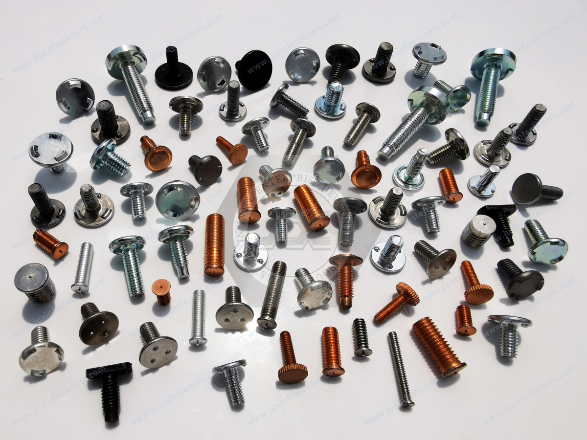
Product Packaging
Packaging Standard
At Juxin Fasteners, we apply standardized export packaging to ensure product protection, traceability, and compliance with international logistics requirements.
1. Standard Export Packaging
Unless otherwise specified, all products will be packed according to our factory standard export packaging, which includes:
Moisture-resistant inner protection
Poly bag or small box packing as required
Reinforced export cartons
Clear labeling with part number, specification, batch number, and quantity
Palletizing for sea or air shipment when necessary
Our standard packaging is designed to ensure safe transportation, efficient warehousing, and long-distance international shipping.
2. Customized Packaging Options
We also provide customized packaging solutions according to customer requirements, including but not limited to:
Private labeling
Customized barcodes
Specific carton dimensions
Retail packaging
Special pallet configuration
Customer-specific marking and identification
So that you know, customized packaging may involve additional costs and extended lead time depending on the complexity of the requirements.
3. Compliance & Quality Assurance
All packaging processes are controlled under our ISO 9001 quality management system to ensure consistency, traceability, and product integrity throughout the supply chain.
Product Pictures
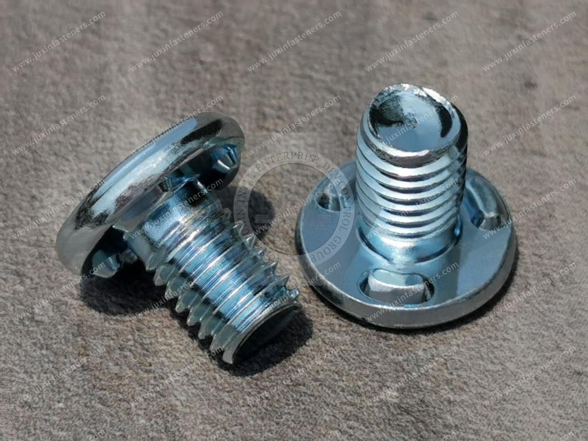
Hot Products
Contact Us
Tel.:
+86 020 8621 0320
+86 020 3121 6067
E-mail:
Technical Support:
Navigation
SEND INQUIREY