Call Us
+86 136 6007 9809
Call Us
+86 136 6007 9809

How do engineers prevent fastener loosening under severe vibration and dynamic cyclic loads?
Fastener vibration loosening prevention requires engineers to understand the complete bolted-joint load path rather than relying on tightening torque alone.
Product Specification
How do engineers prevent fastener loosening under severe vibration and dynamic cyclic loads?
Fastener vibration loosening prevention requires engineers to understand the complete bolted-joint load path rather than relying on tightening torque alone.
A threaded connection can lose preload when dynamic transverse movement causes relative sliding between the connected components.
Under sufficiently severe cyclic displacement, this relative movement can contribute to rotational self-loosening, preload loss, fatigue damage, or other forms of joint degradation.
The important engineering variables include:
bolt preload
friction conditions
joint stiffness
clamped-member stiffness
transverse displacement
external load direction
joint geometry
bearing-surface movement
thread geometry
fastener material and strength
assembly method
locking features
environmental conditions
vibration spectrum and frequency
production variation
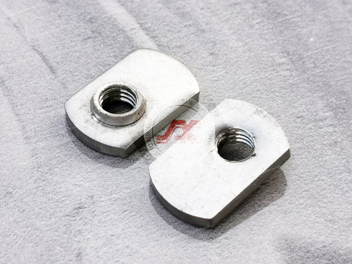
For sheet-metal assemblies, resistance-welded fasteners such as weld nuts and weld studs provide a different anti-rotation architecture from loose nuts
because the welded component is permanently attached to the parent sheet.
This can remove the need to position a separate loose nut during assembly and prevents the welded nut itself from freely rotating relative to the substrate.
However, this should not be interpreted as meaning that every bolted assembly containing a weld nut is automatically vibration-proof.
The complete threaded joint can still experience preload loss, bolt rotation, thread-related failure, fatigue, or joint slip depending on the assembly design and operating conditions.
A useful conceptual model is:
        Transverse Cyclic Loading
                  ↓
        Relative Joint Movement
                  ↓
        Friction / Slip Behavior
                  ↓
       Possible Rotational Back-Off
                  ↓
          Preload Reduction
                  ↓
       Joint Integrity Degradation
For a weld-fastener architecture:
        Parent Sheet / Structure
                  │
                  ▼
       Resistance-Welded Fastener
                  │
                  ▼
        Threaded Mating Component
                  │
                  ▼
            Applied Load

 Welded attachment restricts movement
 of the nut relative to the substrate
The engineering objective is therefore not simply to “add a locking nut.”
It is to determine where relative motion occurs, which component is responsible for maintaining the load path, and whether the selected fastening architecture remains stable under the actual service environment.
JUXIN FASTENERS supplies weld nuts, weld studs, and other industrial fastening components for sheet-metal applications where fastening architecture, welding compatibility, mechanical performance, and production requirements must be considered together.
Traditional fastener discussions often reduce vibration loosening to “insufficient torque.”
That explanation is incomplete.
Correct assembly preload is important, but vibration-induced self-loosening is strongly associated with relative transverse movement within the joint.
When external cyclic loads produce sufficient movement between mating components, frictional resistance can be overcome locally. Once sliding occurs,
the geometry of the threaded interface and bearing surfaces can permit progressive rotational movement.
This is why an assembly can be tightened correctly and still experience loosening under an unfavorable dynamic load condition.
Transverse displacement refers to movement approximately perpendicular to the fastener axis.
This condition is important because it can create relative sliding between:
clamped components
bearing surfaces
thread interfaces
washers or locking elements
the fastener and surrounding structure
The severity of self-loosening depends on the relationship between the applied displacement, joint stiffness, preload, friction, geometry, and other assembly variables.
Therefore, “vibration” by itself is not a sufficiently precise engineering description.
A useful design question is:
How much relative movement can the joint experience before the intended frictional or mechanical locking mechanism becomes ineffective?
Bolt preload is one of the most important variables in joint performance.
A properly designed preload can help maintain contact between mating surfaces and reduce undesirable relative movement.
However, preload should not be treated as an unlimited solution.
Excessive preload can create its own risks, including:
thread damage
fastener yielding
excessive bearing stress
distortion of thin sheet
damage to sensitive components
variation caused by tightening friction
Insufficient preload can increase the likelihood of joint separation or slip.
The correct assembly preload therefore needs to be established from the fastener specification, joint design, material system, tightening method, and applicable engineering requirements.
The Junker test is widely associated with evaluating the tendency of bolted joints to lose preload under transverse vibration.
DIN 65151 provides a commonly referenced framework for dynamic testing of bolted connections.
The test is valuable because it converts a general question such as:
“Will this fastener loosen under vibration?”
into a controlled engineering experiment involving defined test conditions and measurable preload behavior.
However, engineers should avoid treating a Junker result as a universal prediction of field performance.
The test result depends on the:
test fixture
specimen configuration
preload
transverse displacement
frequency
friction conditions
fastener configuration
locking method
number of cycles
acceptance criteria
A laboratory result should therefore be interpreted within the exact test configuration.
One of the important insights from dynamic fastener testing is that joint degradation can begin before obvious complete separation.
A connection may experience:
preload reduction
partial slip
micro-movement
progressive rotation
fretting
fatigue-related damage
before the fastener visibly falls out.
Therefore, engineers should not rely solely on visual inspection when evaluating dynamic joint stability.
A fastener that performs well in one vibration test may not perform identically in another assembly.
Changing:
sheet thickness
surface finish
lubrication
preload
joint stiffness
fastener length
bearing geometry
clamped-member material
external load
vibration direction
can change joint behavior.
For this reason, dynamic testing should be designed around the actual failure risk rather than simply selecting the most convenient laboratory test.
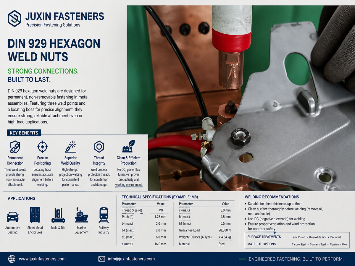
Resistance-welded nuts create an important distinction from loose nuts.
A loose nut can rotate relative to the panel if the assembly configuration allows it.
A properly resistance-welded nut becomes permanently attached to the parent sheet through the welded interface.
This provides several manufacturing and assembly advantages.
Potential advantages include:
fixed threaded location
no loose nut required behind the panel
easier automated assembly
improved accessibility in enclosed structures
controlled fastener positioning
resistance to rotation of the nut relative to the sheet
Common configurations include:
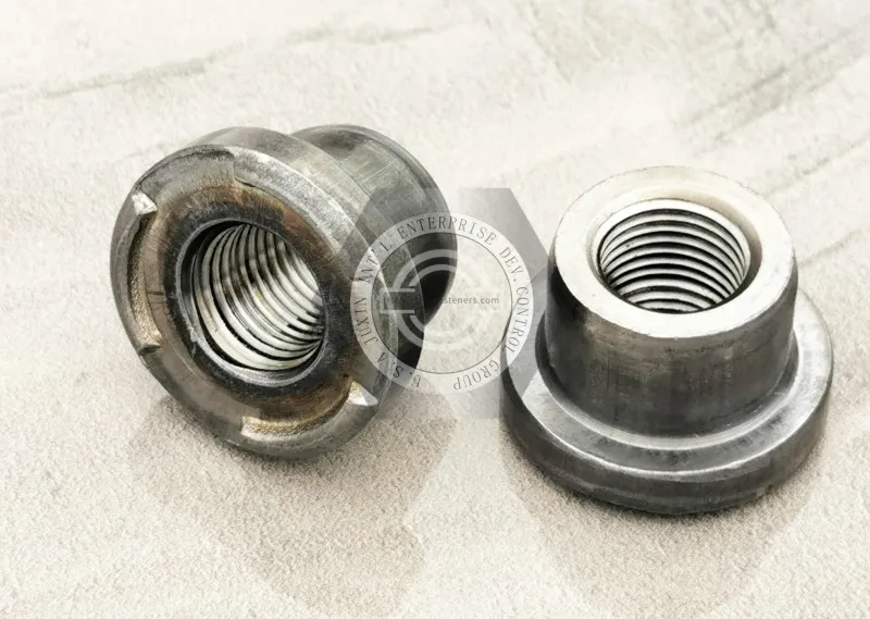
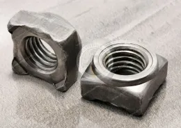
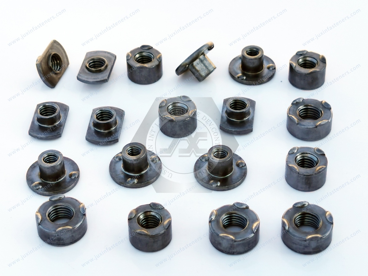
square weld nuts
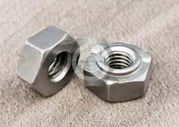
hexagon weld nuts
flange weld nuts
custom weld nuts
The specific geometry should be selected according to:
load path
panel material
sheet thickness
available welding process
assembly access
required thread
surrounding geometry
expected installation load
Weld studs provide a permanently attached threaded or unthreaded mounting point on a sheet-metal structure.
Applications can include:
brackets
cable routing
electrical components
thermal shields
automotive body structures
equipment panels
machinery assemblies
Their anti-rotation and structural behavior depends on the actual stud geometry, weld design, substrate, and load direction.
A welded fastener prevents the welded component from freely rotating relative to the substrate, but this does not automatically prevent every form of vibration-induced loosening in the complete assembly.
For example:
Weld Nut
   ↓
Fixed to Sheet
   ↓
Bolt Installed
   ↓
Bolt / Threaded Joint
   ↓
External Dynamic Load
The weld nut can remain securely attached while the bolt-and-threaded-joint system still experiences preload loss or rotational movement if the complete joint design permits it.
This distinction is critical for technically accurate vibration-resistant fastening design.
Dynamic joint behavior is strongly influenced by the stiffness of the fastener and the clamped members.
Engineers commonly evaluate the relationship between:
fastener stiffness
clamped-member stiffness
preload
external load
joint separation
relative movement
A properly engineered joint transfers external loads through the intended load path while maintaining sufficient contact between the assembled components.
However, thin sheet-metal assemblies can behave differently from rigid machined structures.
Local sheet flexibility can create:
panel movement
flange deformation
contact loss
changing load distribution
local bending
vibration amplification
Therefore, selecting a stronger fastener alone may not solve a vibration problem if the surrounding sheet structure remains flexible.
One of the most useful engineering conclusions is:
Vibration resistance is a joint-design property, not simply a fastener property.
Consider two assemblies using the same weld nut.
Assembly A:
rigid surrounding structure
controlled preload
stable contact surfaces
limited transverse movement
Assembly B:
flexible sheet
larger panel movement
unfavorable load direction
variable preload
greater relative displacement
The same weld nut can experience very different system-level behavior.
This is why procurement teams should avoid evaluating “vibration-resistant fastener” claims without understanding the complete application.
A practical anti-loosening strategy may include several layers.
The tightening method should produce the required assembly condition without exceeding the design limits of the fastener or connected components.
Depending on the application, engineers may use:
torque-controlled tightening
torque-angle methods
tension-controlled methods
other controlled assembly processes
The correct method depends on the joint design and customer requirements.
If relative movement can be reduced, the risk of vibration-induced self-loosening can also be reduced.
Design measures may include:
increasing joint stiffness where appropriate
improving panel support
reducing unnecessary flexibility
improving contact geometry
changing bracket architecture
adding structural reinforcement
Depending on the application, locking strategies can include:
prevailing-torque nuts
mechanical locking features
wedge-locking concepts
thread-locking compounds
castellated or other mechanically retained configurations
welded nut architecture where appropriate
No single locking strategy is universally superior.
The correct choice depends on:
temperature
chemical environment
serviceability
assembly process
vibration level
reuse requirements
corrosion conditions
customer specification
Weld nuts can be particularly valuable when the design requires a fixed threaded attachment point in sheet metal.
Their value may include:
eliminating a loose nut
improving assembly access
preventing nut rotation relative to the panel
enabling automated installation
simplifying enclosed-panel assembly
The weld itself must still be properly designed and validated.
Automotive structures can experience complex combinations of:
road-induced vibration
shock loads
thermal cycling
fatigue
assembly variation
corrosion exposure
dynamic loads
Potential weld-fastener applications include:
brackets
chassis-related components
subframe structures
engine-related brackets
suspension-related components
underbody structures
battery enclosure components
electrical mounting systems
For automotive applications, engineers may need to evaluate dynamic behavior together with:
static strength
fatigue
torque-out resistance
push-out and pull-out performance
corrosion
thermal cycling
production welding consistency
Safety-critical applications require customer-specific engineering validation and should not be qualified based solely on a generic vibration claim.
Agricultural, construction, and industrial equipment can experience severe cyclic loading caused by:
uneven terrain
mechanical impacts
rotating equipment
hydraulic systems
structural movement
repeated service operations
Potential applications include:
equipment brackets
protective panels
hydraulic supports
electrical enclosures
cab structures
guards
mounting points
For these environments, engineers should consider both vibration and shock loading.
A static pull-out result alone may not describe long-term dynamic behavior.
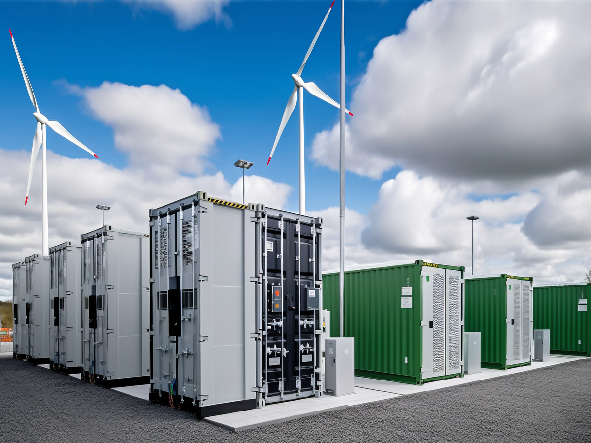
Wind turbines and other rotating industrial systems create dynamic operating conditions that can affect fastening performance.
Potential concerns include:
cyclic structural loading
vibration
fatigue
temperature variation
corrosion
maintenance access
long service intervals
Welded fastening components may be useful for selected sheet-metal brackets, covers, electrical mounting structures, and auxiliary components.
However, critical structural connections should be designed and qualified according to the applicable engineering and industry requirements rather than relying on a generic “vibration-proof” designation.
Electrical equipment can also contain sheet-metal assemblies where vibration stability is important.
Applications may include:
electrical cabinets
control panels
industrial equipment housings
power equipment
cable-management brackets
mounting brackets
grounding or bonding components
For grounding applications, mechanical retention and electrical bonding are separate engineering considerations.
The weld fastener may provide the mechanical attachment point, while electrical continuity depends on the complete interface, coating system, contact design, and applicable electrical requirements.
Vibration performance should be considered during product design rather than after production problems appear.
Avoid placing the fastener where:
panel deformation is excessive
access is poor
welding electrodes cannot reach properly
surrounding geometry creates unintended bending
the load path is poorly defined
If the panel is highly flexible, engineers should investigate whether:
a flange can be added
a reinforcement can be introduced
the load can be redistributed
the mounting position can be changed
the bracket geometry can be improved
before simply increasing fastener size.
Projection geometry affects the welding process and joint behavior.
The selected configuration should be compatible with:
fastener geometry
sheet material
sheet thickness
electrode geometry
welding equipment
production cycle
required mechanical performance
Weld projections should therefore be treated as part of the joint design rather than merely a feature of the fastener.
Supplier quality control should extend beyond dimensional inspection.
Depending on project requirements, useful controls may include:
material identification
dimensional inspection
thread inspection
surface condition
coating verification where specified
welding current monitoring
electrode force control
electrode condition
tooling alignment
projection geometry
process parameter control
sample destructive testing where required
Depending on the application:
push-out testing
pull-out testing
torque-out testing
tensile testing
shear testing
vibration testing
fatigue testing
environmental testing
The exact test plan should be established according to the actual engineering risk.
Procurement managers should ask more than:
“Is this weld nut vibration-resistant?”
Better supplier-development questions include:
What weld fastener geometry is proposed?
What parent sheet material is assumed?
What sheet thickness is being evaluated?
What welding process is required?
Has the welded joint been mechanically validated?
What failure modes were observed?
Was the test performed on a representative assembly or a laboratory coupon?
What vibration or cyclic-load condition was used?
Which test method or customer specification was followed?
What production controls maintain weld consistency?
How are dimensional and material changes controlled?
Can the supplier support prototype and production validation?
What documentation will be supplied with the production program?
These questions convert a vague “anti-loosening” claim into an auditable engineering requirement.
A vibration-related fastening failure can be expensive even when the fastener itself has a low unit price.
Potential costs include:
line-side rework
loose-component recovery
production downtime
field service
warranty claims
customer complaints
engineering investigation
supplier corrective action
product redesign
A more appropriate procurement calculation is:
Fastener Unit Cost + Assembly Cost + Quality Cost + Failure Risk + Maintenance Cost
This is particularly important for OEM applications where a small fastening component can affect a much larger assembly.
A robust engineering workflow can follow these stages:
Application Load Definition
          ↓
Joint Architecture Review
          ↓
Fastener Selection
          ↓
Parent Sheet / Material Review
          ↓
Welding Process Development
          ↓
Prototype Assembly
          ↓
Static Mechanical Validation
          ↓
Dynamic / Vibration Validation
          ↓
Failure Mode Analysis
          ↓
Design or Process Optimization
          ↓
Production Validation
          ↓
Ongoing Quality Control
This workflow prevents the common mistake of performing vibration testing only after the fastener design has already been locked.
When a field or laboratory assembly loosens, the correct question is not simply:
“Which locking nut should we use?”
The first question should be:
“What type of joint movement or failure actually occurred?”
Investigate:
Possible causes may include:
insufficient preload
transverse slip
unfavorable friction conditions
inadequate locking strategy
joint separation
Investigate:
weld interface integrity
incomplete weld formation
projection collapse
substrate deformation
weld fastener geometry
welding process consistency
This is related to weld nut spin-out analysis.
Investigate:
sheet thickness
material properties
panel stiffness
local geometry
fastener position
load distribution
Investigate:
thread specification
mating fastener
tightening condition
material combination
thread engagement
installation damage
Investigate:
embedment
joint settling
surface conditions
transverse movement
friction variation
assembly process variation
Each failure mechanism requires a different corrective action.
Weld fasteners can reduce the need for separate loose nuts in sheet-metal assemblies.
This may provide manufacturing benefits such as:
fewer loose components
improved assembly access
easier automation
reduced nut handling
fixed threaded locations
However, this does not mean every weld nut eliminates every form of auxiliary locking.
The complete bolt joint may still require an appropriate locking strategy depending on the application.
The correct engineering question is:
Does the selected fastening architecture provide sufficient resistance to the actual joint movement and service loads?
That question is much more useful than simply asking whether a component is marketed as “vibration-proof.”
For engineering teams, the most valuable supplier is not necessarily the supplier offering the strongest-looking fastener.
The better supplier is the one that can connect:
Fastener Geometry → Parent Material → Welding Process → Joint Mechanics → Validation → Production Control
For procurement teams, this creates a more robust supplier qualification model.
A technically mature RFQ should therefore define:
application
load case
parent sheet
fastener geometry
thread
welding process
coating
environmental requirements
validation requirements
annual volume
packaging
quality documentation
change-control requirements
This information reduces the risk of receiving technically non-equivalent quotations.
A vibration-related engineering search often represents a deeper procurement requirement.
The actual customer journey may be:
Vibration Problem
        ↓
Joint Failure Investigation
        ↓
Fastener / Joint Architecture Review
        ↓
Weld Nut or Weld Stud Selection
        ↓
Prototype Samples
        ↓
Welding Process Development
        ↓
Mechanical / Dynamic Validation
        ↓
Production Approval
        ↓
OEM Sourcing
        ↓
Long-Term Supply Program
This creates a natural commercial pathway from technical search intent to an OEM RFQ.
Instead of selling only a fastener, the supplier becomes part of the customer's joint engineering and sourcing decision.
JUXIN FASTENERS supports industrial fastening requirements involving:
weld nuts
weld studs
self-clinching fasteners
blind rivet nuts
threaded inserts
CNC-machined fasteners
custom screws and bolts
stainless steel fasteners
high-strength fasteners
custom engineered fastening components
For vibration-sensitive sheet-metal applications, the correct product selection depends on the complete application.
Useful information for an engineering review includes:
2D drawing
3D CAD model where available
parent sheet material
sheet thickness
thread requirement
fastener geometry
welding process
expected load direction
vibration conditions
coating requirement
application industry
annual volume
required validation
JUXIN FASTENERS can then evaluate the fastening requirement from both an engineering and OEM sourcing perspective.
This article should connect naturally to the following JUXIN FASTENERS engineering and procurement resources:
Weld Nut Spin Failure Analysis & Prevention
Weld Stud Push-Out & Pull-Out Failure Analysis
Fastener Push-Out & Pull-Out Testing
Projection Welding Process & DFM Joint Optimization
Weld Nuts vs. Self-Clinching Nuts
Weld Nuts vs. Blind Rivet Nuts
Substrate Material Compatibility for Weld Fasteners
Sheet Metal Thickness Guidelines for Weld Fasteners
Edge Distance & Hole Clearance for Weld Fasteners
Automotive BIW Weld Fasteners
EV Battery Enclosure Weld Fasteners
Heavy Machinery & Agricultural Weld Fasteners
Electrical Enclosure Weld Fasteners & Grounding
Custom Weld Fasteners
Fastener Procurement & RFQ Best Practices
Fastener Supplier Quality Audits & Certifications
Fastener Surface Finishes & Coatings
Together, these pages create a structured knowledge path:
Vibration Problem → Failure Analysis → Joint Design → Weld Fastener Selection → Mechanical Testing → Quality Validation → OEM Procurement
Fasteners can self-loosen when cyclic transverse movement causes relative sliding within the joint. Under sufficiently severe conditions,
this movement can overcome frictional resistance and contribute to rotational back-off and preload loss.
No. Proper preload is important, but vibration behavior also depends on joint stiffness, transverse displacement, friction conditions, joint geometry, external loads, and the selected locking strategy.
The Junker test is a dynamic test approach used to evaluate the behavior of bolted joints under transverse cyclic loading,
particularly preload loss associated with vibration-induced joint movement. DIN 65151 is a commonly referenced standard for this type of testing.
No. Its applicability depends on the engineering requirement and test program. Customer specifications, product standards,
industry requirements, and application-specific validation may define different or additional testing requirements.
No. A properly welded nut is fixed to the parent sheet and cannot freely rotate relative to the substrate in the way a loose nut can.
However, the complete threaded joint can still experience preload loss, bolt rotation, fatigue, or joint movement depending on the application.
Neither is universally better. Weld nuts provide a permanently attached threaded location in sheet-metal structures,
while lock washers and other locking technologies address different aspects of threaded-joint behavior. Selection should be based on the actual joint design, assembly process, environment, and customer requirements.
Not necessarily. If the root cause is transverse joint slip, insufficient preload, panel flexibility, or inadequate locking, increasing bolt strength alone may not address the failure mechanism.
Depending on the application, validation may include pull-out, push-out, torque-out, tensile, shear, vibration, fatigue, corrosion, thermal cycling, or combined-load testing.
Provide the fastener drawing, parent sheet material and thickness, welding method, expected load, vibration conditions where known,
application environment, coating requirements, annual volume, and required validation standards or customer specifications.
JUXIN FASTENERS can evaluate custom weld fastener requirements based on engineering drawings, application conditions, materials, welding process, and production requirements.
If your application involves vibration-sensitive sheet-metal assemblies, weld nuts, weld studs, or custom weld fasteners, send the engineering information before finalizing the fastening architecture.
For the most useful technical review, provide:
2D engineering drawing
3D CAD model
parent sheet material
sheet thickness
fastener specification
thread requirement
welding method
vibration or cyclic-load conditions
expected load direction
environmental requirements
coating specification
annual volume
prototype quantity
validation requirements
Email: info@juxinfasteners.com
JUXIN FASTENERS — Precision Fastening Solutions Since 2003.
For OEM engineering development, supplier qualification, dynamic joint validation, and global fastening procurement, contact JUXIN FASTENERS with your drawings and application requirements.
Product Packaging
Packaging Standard
At Juxin Fasteners, we apply standardized export packaging to ensure product protection, traceability, and compliance with international logistics requirements.
1. Standard Export Packaging
Unless otherwise specified, all products will be packed according to our factory standard export packaging, which includes:
Moisture-resistant inner protection
Poly bag or small box packing as required
Reinforced export cartons
Clear labeling with part number, specification, batch number, and quantity
Palletizing for sea or air shipment when necessary
Our standard packaging is designed to ensure safe transportation, efficient warehousing, and long-distance international shipping.
2. Customized Packaging Options
We also provide customized packaging solutions according to customer requirements, including but not limited to:
Private labeling
Customized barcodes
Specific carton dimensions
Retail packaging
Special pallet configuration
Customer-specific marking and identification
So that you know, customized packaging may involve additional costs and extended lead time depending on the complexity of the requirements.
3. Compliance & Quality Assurance
All packaging processes are controlled under our ISO 9001 quality management system to ensure consistency, traceability, and product integrity throughout the supply chain.
Product Pictures
Contact Us
Tel.:
+86 020 8621 0320
+86 020 3121 6067
E-mail:
Technical Support:
Navigation
SEND INQUIREY