Call Us
+86 136 6007 9809
Call Us
+86 136 6007 9809

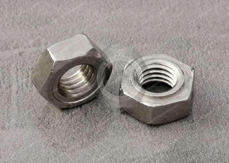
Hexagonal weld nuts provide a permanent threaded fastening point on sheet metal and fabricated metal components,
making them useful where an assembly requires a repeatable internal thread without installing a separate loose nut during final assembly.
Product Specification
Hexagonal weld nuts provide a permanent threaded fastening point on sheet metal and fabricated metal components,
making them useful where an assembly requires a repeatable internal thread without installing a separate loose nut during final assembly.
For OEM applications, selecting the right hexagonal weld nut is not simply a matter of choosing a thread size.
The fastener geometry, pilot configuration, projection design, sheet material, sheet thickness, hole geometry, surface condition, welding equipment, and production requirements all influence the final joint.
This guide explains how engineers and procurement teams can evaluate hexagonal weld nuts from both an engineering and sourcing perspective.
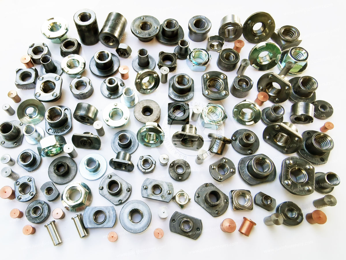
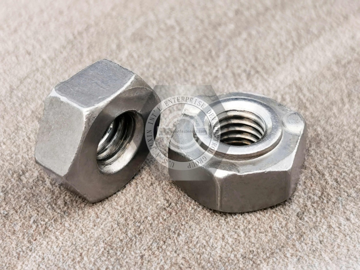
Hexagonal weld nuts are internally threaded metal fasteners designed to be permanently attached to a metal substrate, commonly by resistance projection welding.
The hexagonal body provides an external geometry that can resist rotation after welding, while the internal thread provides a reusable attachment point for a screw or bolt.
Depending on the design, hexagonal weld nuts may incorporate:
Welding projections
A locating pilot
Different thread sizes
Different body dimensions
Metric or inch thread configurations
Different materials and surface treatments
Custom dimensions for OEM applications
A hexagonal weld nut should be treated as part of a complete fastening system rather than as an isolated component.
The final joint depends on the relationship between:
Weld nut + sheet metal + hole + welding process + surface condition + assembly load
This is particularly important for automotive, electrical equipment, industrial machinery, and other high-volume sheet-metal assemblies.
One of the main advantages of weld nuts is that they can create a permanent threaded attachment point before the final assembly operation.
This can simplify downstream assembly because the nut does not need to be manually positioned behind the sheet during screw installation.
Typical advantages include:
Permanent internal threads
Suitable for automated or semi-automated assembly processes
Reduced need for loose nuts
Good compatibility with fabricated sheet-metal components
Repeatable positioning when correctly designed
Compatibility with high-volume production
Potential for integration into stamping and welding processes
For OEM production, the most important question is not simply whether a weld nut can be welded to a sheet.
The engineering question is whether the selected weld nut can provide the required joint performance consistently across the actual production process.
Hexagonal weld nuts are available with different locating configurations.
The choice between a pilot and a non-pilot design depends on how the fastener will be positioned and controlled during welding.
A pilot, sometimes called a locating spigot, extends into the prepared hole in the sheet.
Its primary function is positioning.
A pilot can help:
Locate the nut relative to the hole
Improve repeatability during welding
Assist fixture-based positioning
Maintain alignment between the threaded feature and the sheet opening
However, pilot geometry must be matched to the actual hole geometry and tolerance.
There is no universal pilot-to-hole clearance that applies to every weld nut application.
A pilot should therefore be specified together with:
Hole diameter
Hole tolerance
Sheet thickness
Nut geometry
Welding fixture
Assembly requirements
A pilot may also influence weld spatter behavior around the thread opening, but it should not automatically be treated as a guaranteed thread-protection or sealing feature.
Non-pilot weld nuts do not use a locating spigot.
They may be suitable where the production process already provides sufficient positioning through:
Welding fixtures
Automated feeding equipment
Tooling
Vision systems
Dedicated locating features
The advantage of a non-pilot design can be simpler part geometry, but the production process must provide reliable positioning.
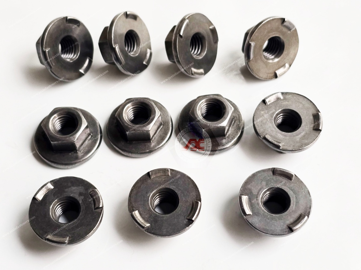
Projection welding uses localized raised features on the weld nut to concentrate electrical current and welding force at defined contact points.
During the welding cycle, heat is generated at the contact areas between the projections and the sheet.
The projections then collapse or deform as the weld develops, creating the permanent attachment.
Actual weld formation depends on the complete welding system, including:
Weld nut material
Sheet material
Sheet thickness
Projection geometry
Number and arrangement of projections
Electrode design
Electrode force
Welding current
Welding time
Surface condition
Coatings
Equipment condition
Production environment
For this reason, projection geometry should not be evaluated independently from the welding process.
A geometry that performs well on one substrate or welding setup may require different process parameters on another.
Three-projection and four-projection designs are both used in resistance projection welding applications.
However, there is no universal rule that one configuration is always stronger.
The number and arrangement of projections affect:
Current distribution
Heat generation
Weld formation
Mechanical stability
Welding process sensitivity
Interaction with the sheet surface
The correct design should be validated against the actual:
Fastener material
Sheet material
Sheet thickness
Hole configuration
Welding equipment
Electrode setup
Required joint performance
For OEM production, physical validation is more meaningful than selecting a projection configuration based solely on a generalized ranking.
Design for Manufacturing should begin before the weld nut is released for production.
A weld nut can be technically suitable but still create manufacturing problems if the sheet-metal design, hole geometry, tooling, or welding process is not considered together.
For piloted weld nuts, the hole must be compatible with the pilot geometry.
The engineering drawing should define the relevant hole diameter and tolerance based on the selected fastener and production process.
Do not use a generic clearance value without validating the actual component.
Projection geometry must be considered together with sheet thickness and material.
There is no universal projection-height-to-sheet-thickness ratio that guarantees correct welding.
The selected combination should be validated through the intended welding process.
Important factors include:
Sheet material
Sheet thickness
Nut material
Projection geometry
Welding current
Electrode force
Welding time
Required joint performance
Weld nuts installed close to sheet edges require additional engineering attention.
The available edge distance can influence:
Sheet deformation
Heat distribution
Electrode access
Local weld formation
Part distortion
Production repeatability
There is no single edge-distance formula that should be applied to every weld nut design.
The actual minimum distance should be established according to the component geometry, welding process, substrate, fastener dimensions, and applicable design requirements.
The sheet surface should provide suitable contact with the weld nut projections.
Excessive local deformation, stamping features, burrs, or uneven surfaces may affect contact conditions during welding.
DFM review should therefore consider the complete interface rather than only the nominal sheet thickness.
Surface treatments can affect resistance welding behavior.
Examples include:
Zinc-coated steel
Galvanized sheet
Phosphated surfaces
Oiled surfaces
Painted surfaces
Other protective coatings
The welding process should be evaluated with the actual substrate condition used in production.
Surface condition can influence electrical resistance, electrode condition, weld formation, and process stability.
These fastening methods solve related but different assembly problems.
| Feature | Hexagonal Weld Nuts | Self-Clinching Nuts | Blind Rivet Nuts |
|---|---|---|---|
| Installation principle | Welding | Mechanical clinching | Blind mechanical installation |
| Permanent attachment | Yes | Yes | Yes |
| Requires welding equipment | Yes | No | No |
| Blind-side access required | Typically not for the final screw assembly | Usually installed before final assembly | Designed for blind installation |
| Typical substrate | Metal sheet and fabricated metal parts | Suitable sheet metals within product/design limits | Thin-wall or inaccessible substrates |
| Positioning method | Pilot, fixture, tooling, or automation | Prepared hole and installation tooling | Prepared hole and installation tool |
| Process integration | Strong fit for welded sheet-metal production | Strong fit for mechanical installation processes | Strong fit where backside access is limited |
| Main selection concern | Weld process and joint formation | Material compatibility and installation conditions | Hole, grip range, installation process, and joint performance |
The correct choice depends on the production architecture.
A weld nut is not automatically a better alternative to a self-clinching nut or blind rivet nut.
Each technology should be evaluated against the actual substrate, access conditions, production equipment, assembly sequence, and performance requirements.
Automotive and EV assemblies contain many sheet-metal and fabricated components that require reliable threaded attachment points.
Potential applications include:
Brackets
Structural sheet-metal assemblies
Battery-related components
Electrical mounting structures
Chassis-related components
Interior and exterior assemblies
Protective covers
Equipment mounting points
In EV applications, material combinations and surface treatments can vary significantly.
Engineering evaluation should consider:
Base material
Sheet thickness
Coating condition
Welding process
Required mechanical performance
Environmental exposure
Assembly sequence
For production programs, weld-nut selection should be integrated into the component DFM and welding-process review rather than treated as a standalone purchasing decision.
Electrical cabinets, control boxes, power equipment housings, and sheet-metal enclosures frequently require internal threaded attachment points.
Hexagonal weld nuts can provide permanent mounting points for:
Covers
Brackets
Cable-management components
Electrical components
Grounding-related hardware
Internal support structures
Protective panels
The engineering review should consider the enclosure material, coating, welding access, required thread size, assembly load, and environmental requirements.
Where sealing or ingress protection is required, it must be designed and validated as part of the complete enclosure system. A weld nut itself should not be assumed to provide a particular IP rating.
Industrial equipment often combines sheet-metal covers, brackets, frames, guards, and fabricated assemblies.
Weld nuts can be integrated into these components to provide permanent threaded mounting points.
Typical applications include:
Machine covers
Equipment frames
Protective guards
Brackets
Control panels
Industrial cabinets
Fabricated support structures
For machinery OEMs, repeatability and production efficiency can be as important as the nominal mechanical performance of the fastener.
A weld-nut solution should therefore be evaluated for the complete manufacturing process.
A practical selection process should follow the actual production requirements.
Specify:
Thread standard
Thread size
Pitch
Internal thread requirements
Mating screw or bolt
Identify:
Base material
Sheet thickness
Surface condition
Coating
Formed features near the installation area
Confirm whether the nut will be installed by:
Resistance projection welding
Automated welding
Manual or semi-automated welding
A dedicated production fixture
A pilot may be appropriate where accurate positioning through a prepared hole is beneficial.
If a pilot is selected, the hole and pilot should be engineered as a matched system.
Review:
Projection count
Projection arrangement
Projection geometry
Electrode access
Welding-process compatibility
Consider the required material and finish based on:
Corrosion environment
Welding compatibility
Appearance
Customer specifications
Downstream assembly requirements
Before mass production, validate the complete system:
Fastener + substrate + hole + welding process + surface condition + assembly requirements
This is the most reliable way to confirm production suitability.
A qualified OEM supplier should provide more than a low unit price.
The supplier should be able to identify and control the material used for the specified application.
Critical dimensions should be controlled according to the approved drawing and applicable specifications.
Internal threads should be inspected according to the agreed thread specification and inspection requirements.
For high-volume production, procurement teams should evaluate whether the weld nut geometry is compatible with the intended feeding and automation system.
A capable supplier should be able to discuss:
Material selection
Pilot configuration
Projection geometry
Sheet-metal interface
Welding considerations
Surface treatment
Custom dimensions
OEM drawing requirements
The best sourcing decision is usually based on total production suitability rather than unit price alone.
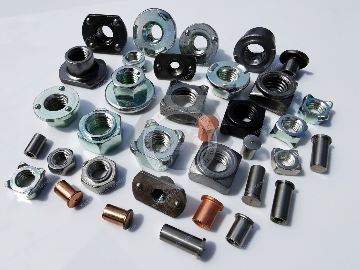
Several mistakes repeatedly create problems during production.
The sheet material and thickness directly influence the welding process.
Projection geometry must be validated against the actual fastener, substrate, and welding system.
Projection count is only one part of weld-joint design.
A pilot can assist positioning and may influence spatter behavior, but thread protection depends on the complete welding setup.
Edge distance depends on the actual component and welding process.
Coatings and surface conditions can affect resistance welding.
A low-cost weld nut can become expensive if it creates feeding, welding, inspection, or production-stability problems.
Hexagon weld nuts are commonly associated with standards such as DIN 929 where applicable.
However, a standard reference should not replace the actual OEM drawing or purchase specification.
A production specification may define additional requirements for:
Material
Thread
Dimensions
Tolerances
Projection geometry
Pilot configuration
Surface treatment
Inspection
Packaging
Traceability
For OEM programs, the approved drawing and agreed technical specification should remain the primary reference.
To receive an accurate quotation and engineering recommendation, an RFQ should include as much of the following information as available:
2D drawing
3D CAD model where available
Thread size and standard
Nut material
Overall dimensions
Pilot dimensions
Projection configuration
Sheet material
Sheet thickness
Hole diameter and tolerance
Welding method
Surface treatment
Corrosion requirements
Operating environment
Required production volume
Annual demand
Prototype requirements
Inspection requirements
Packaging requirements
Applicable standards
Production schedule
If the application is still in the design stage, provide the substrate information and intended welding process even if the final weld-nut geometry has not yet been selected.
This allows the supplier to evaluate the fastening system rather than quote a generic catalog item.
JUXIN FASTENERS supplies weld nut solutions for OEM and industrial fastening applications, including:
Hexagonal weld nuts
Projection weld nuts
Piloted weld nuts
Custom weld nuts
Weld studs
Weld pins
CD weld fasteners
Arc weld fasteners
Custom OEM fastening components
For customized applications, JUXIN FASTENERS can evaluate the fastener together with the customer's substrate, installation method, dimensional requirements, surface treatment, and production requirements.
For OEM RFQs, send the drawing, specifications, application information, and estimated quantity to:
Related fastening solutions may include:
Weld Nuts Solutions
Weld Studs Solutions
Weld Pins Solutions
CD Weld Fasteners
Arc Weld Fasteners
Automotive Fastening Solutions
EV Fastening Solutions
Electrical Equipment Fastening Solutions
Industrial Machinery Fastening Solutions
These solution areas should be evaluated according to the actual assembly method and application requirements.
Hexagonal weld nuts are used to create permanent internal threaded attachment points on sheet-metal and fabricated metal components.
They can be suitable for sheet-metal applications, but suitability depends on the nut design, sheet material, sheet thickness, hole geometry, welding process, and required joint performance.
A correctly welded nut can provide resistance to rotation through the welded joint and the geometry of the fastener. Actual performance depends on the weld formation and application conditions.
A pilot provides a locating feature that enters the prepared hole. A non-pilot design relies more heavily on fixtures, tooling, or other positioning methods.
There is no universal answer. Projection count affects current distribution and weld formation, but actual performance must be evaluated with the specific fastener, substrate, and welding process.
They can be used in applications involving coated sheet materials, but the actual surface condition must be considered during welding-process development and validation.
A pilot may influence the area around the thread opening, but it should not be treated as a guaranteed spatter-protection feature. Thread protection depends on the complete fastener and welding setup.
Yes, weld nuts are widely applicable to sheet-metal fastening in automotive and electrification-related assemblies. The correct design must be validated against the specific material, coating, welding process, and performance requirements.
Yes. Custom weld nut designs can be developed according to OEM drawings and application requirements.
The most useful information includes the drawing, thread, material, dimensions, pilot and projection requirements, substrate material and thickness, hole geometry, welding method, surface treatment, required quantity, inspection requirements, and applicable standards.
Selecting a hexagonal weld nut should begin with the complete joint rather than the fastener alone.
The key questions are:
What material and thickness is the substrate?
What thread is required?
Is a pilot needed for positioning?
What hole geometry and tolerance are available?
Which welding process will be used?
What projection configuration is appropriate?
How will the surface treatment affect welding?
What joint performance must be validated?
Can the fastener be reliably fed and welded in production?
Can the supplier maintain the required dimensional and process consistency?
When these factors are considered together, weld-nut selection becomes a DFM and manufacturing-engineering decision rather than simply a component purchasing decision.
If you are developing a new sheet-metal assembly or looking for an alternative weld nut supplier, JUXIN FASTENERS can review your drawing and application requirements.
Send your drawing, substrate information, thread specification, welding process, annual volume, and any existing fastener specification to:
JUXIN FASTENERS — Precision Fastening Solutions Since 2003
Product Packaging
Packaging Standard
At Juxin Fasteners, we apply standardized export packaging to ensure product protection, traceability, and compliance with international logistics requirements.
1. Standard Export Packaging
Unless otherwise specified, all products will be packed according to our factory standard export packaging, which includes:
Moisture-resistant inner protection
Poly bag or small box packing as required
Reinforced export cartons
Clear labeling with part number, specification, batch number, and quantity
Palletizing for sea or air shipment when necessary
Our standard packaging is designed to ensure safe transportation, efficient warehousing, and long-distance international shipping.
2. Customized Packaging Options
We also provide customized packaging solutions according to customer requirements, including but not limited to:
Private labeling
Customized barcodes
Specific carton dimensions
Retail packaging
Special pallet configuration
Customer-specific marking and identification
So that you know, customized packaging may involve additional costs and extended lead time depending on the complexity of the requirements.
3. Compliance & Quality Assurance
All packaging processes are controlled under our ISO 9001 quality management system to ensure consistency, traceability, and product integrity throughout the supply chain.
Product Pictures
Contact Us
Tel.:
+86 020 8621 0320
+86 020 3121 6067
E-mail:
Technical Support:
Navigation
SEND INQUIREY