Call Us
+86 136 6007 9809
Call Us
+86 136 6007 9809

Product Specification
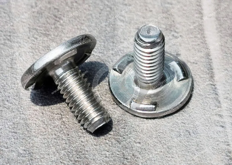
Projection weld studs provide a permanent male threaded fastening point on sheet-metal and fabricated metal components.
Unlike a loose bolt-and-nut assembly, the stud is attached to the substrate before the final assembly operation, allowing a mating component to be positioned and secured with a nut or other threaded component.
In resistance projection welding, engineered projections on the underside of the stud head concentrate electrical current and mechanical force at defined contact areas.
The welding process then develops localized heat and pressure at the interface between the stud and the sheet.
For OEM applications, projection weld stud selection should be evaluated as a complete system:
Stud geometry + substrate + surface condition + welding equipment + welding parameters + assembly load
This approach is more reliable than selecting a stud based only on thread size or nominal head dimensions.
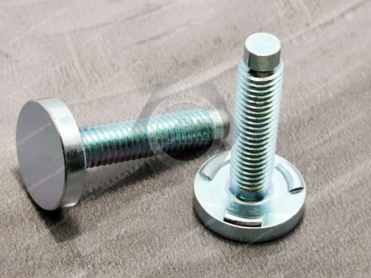
Projection weld studs are externally threaded metal fasteners designed to be permanently attached to a metallic substrate using resistance projection welding.
A typical configuration consists of:
Threaded shank
Stud head or flange
One or more welding projections
Optional locating features depending on the design
The threaded shank provides the male fastening interface, while the welded head transfers assembly loads into the sheet metal.
A simplified section is:
              THREADED STUD SHAFT
                    ||||
                    ||||
             +------+------+
             |   STUD HEAD |
             +--+-------+--+
                ^       ^
             PROJ.    PROJ.
                \       /
================================
          SHEET METAL
================================
The actual weld interface depends on the projection geometry, substrate, electrode configuration, and welding parameters.
Projection weld studs are particularly useful when a manufacturer wants to integrate threaded attachment points directly into a stamped or fabricated component before downstream assembly.
Typical applications include:
Automotive body and chassis components
EV and battery-related sheet-metal structures
Electrical enclosures
Industrial machinery
Appliance assemblies
Brackets and fabricated frames
Cable and component mounting systems
Resistance projection welding concentrates electrical resistance at deliberately formed projections.
During welding, the stud and sheet are positioned between electrodes. Electrode force establishes contact while welding current passes through the projection areas.
A simplified process is:
      UPPER ELECTRODE
             ↓
       +-------------+
       | WELD STUD   |
       +--P-------P--+
          ↓       ↓
================================
          SHEET METAL
================================
             ↑
      LOWER ELECTRODE
The projections provide controlled contact points where electrical resistance and heating can be concentrated.
The welding sequence normally involves several stages:
The stud is positioned against the substrate and the electrodes apply force.
The objective is to establish stable contact before the welding current is applied.
Electrical current passes through the stud-sheet interface.
The localized resistance at the projections produces heat according to the basic resistance-welding relationship:
Q ∝ I²Rt
where:
Q represents generated heat
I represents welding current
R represents electrical resistance
t represents current duration
This relationship explains why current, resistance, and welding time must be considered together rather than optimized independently.
As the projection heats and deforms, the contact area changes and the weld develops at the interface.
The actual weld formation depends on:
Stud material
Sheet material
Sheet thickness
Projection geometry
Electrode force
Welding current
Current duration
Surface condition
Coatings
Electrode condition
Welding equipment
After current stops, electrode force may be maintained while the weld region cools and solidifies.
The exact welding schedule should be developed and validated for the specific fastener and substrate combination.
Projection weld studs can use different welding-face geometries.
Common approaches include multiple discrete projections or other engineered contact features.
The correct geometry depends on the stud design and welding process.
A multi-point design uses several localized projections on the underside of the head.
Potential advantages include:
Defined electrical contact points
Controlled heat concentration
Compatibility with flat electrode tooling
Ability to distribute the welded interface around the stud head
However, the number of projections should not be treated as a universal indicator of joint strength.
Three projections are not automatically stronger than four, and four projections are not automatically stronger than three.
Actual performance depends on the complete welding system and the resulting weld formation.
Some specialized stud designs may use a continuous or annular welding feature.
Such geometries can provide a continuous contact path around the head, depending on the design.
However, a continuous welding feature should not automatically be described as a hermetic seal or pressure-tight joint.
If fluid or gas sealing is required, the complete assembly must be specifically designed and validated for that requirement.
Projection weld studs should be compared with alternative technologies according to the manufacturing process rather than through absolute strength rankings.
| Criterion | Projection Weld Studs | Press-In / Self-Clinching Studs | Arc Weld Studs | CD Weld Studs |
|---|---|---|---|---|
| Primary joining method | Resistance projection welding | Mechanical installation | Arc welding process | Capacitor discharge welding |
| Thread configuration | External | External | External | External |
| Heat introduced to substrate | Localized welding heat | No welding heat | Localized arc welding heat | Very short welding cycle |
| Backside access | Depends on electrode arrangement and component geometry | Installation tooling access required | Depends on welding gun access | Generally suitable where the welding tool can access the installation side |
| Typical selection driver | Integrated sheet-metal production | Mechanical installation without welding | Stud welding applications | Rapid localized stud welding |
| Automation potential | High when stud geometry and feeding are suitable | High | High in suitable applications | High |
| Main engineering concern | Weld formation and process compatibility | Sheet material and installation conditions | Welding process and substrate | Stud type, surface condition, energy and process control |
The right technology depends on the component design and manufacturing environment.
There is no universal rule that projection welding is superior to every other stud-installation method.
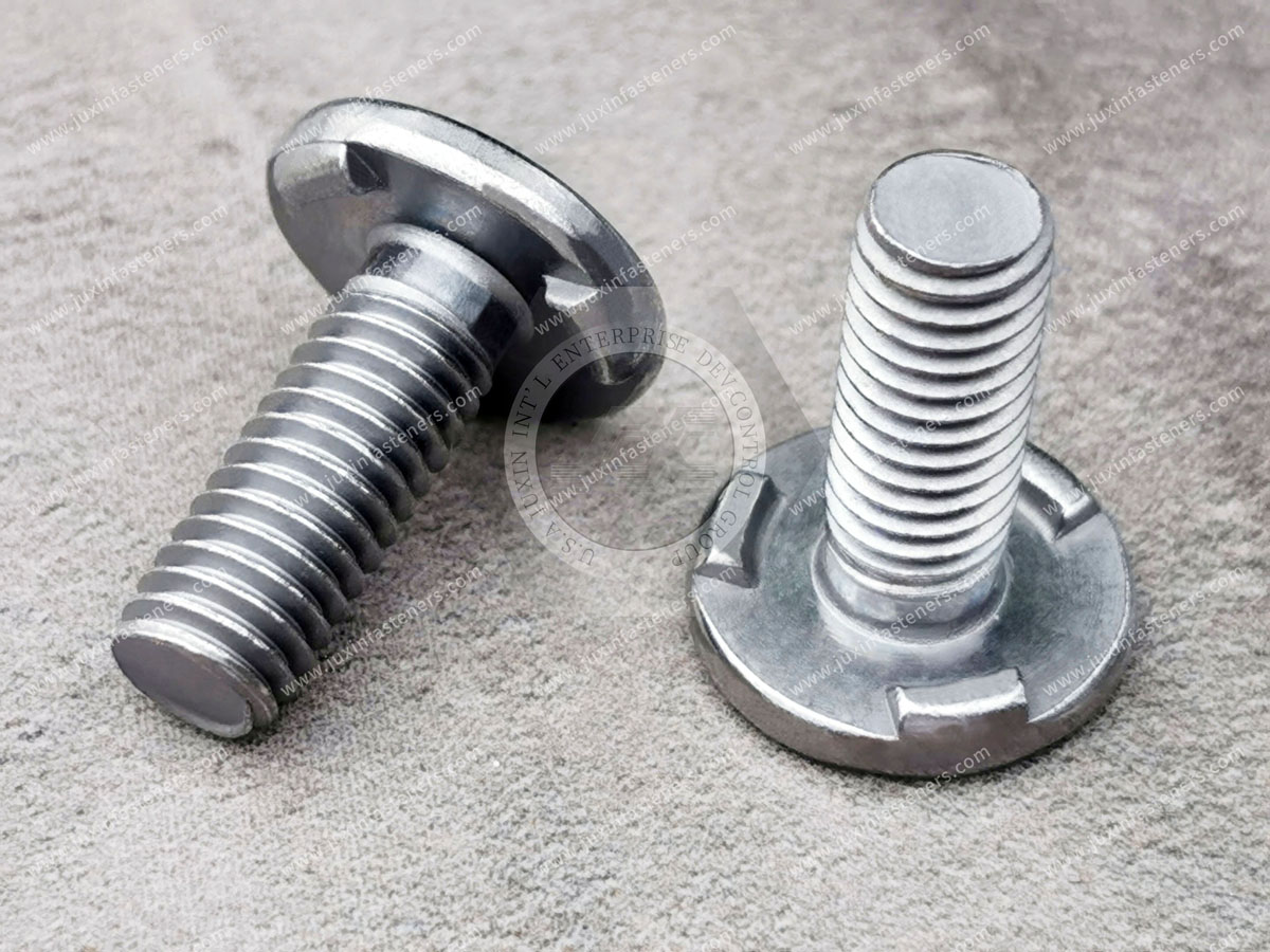
DFM should begin with the complete stud-to-sheet interface.
The first question should be whether the stud and substrate are compatible with the selected resistance welding process.
Review:
Sheet material
Sheet thickness
Stud material
Stud head geometry
Projection design
Surface treatment
Electrode configuration
Avoid selecting a stud first and attempting to force the welding process around it.
The relationship between stud head geometry and sheet thickness affects heat flow, deformation, electrode contact, and weld formation.
There is no universal projection-height-to-sheet-thickness ratio that guarantees a successful weld.
The correct relationship must be established through the specific fastener design and welding process.
Projection weld studs positioned close to sheet edges require additional review.
Important considerations include:
Available electrode access
Local sheet stiffness
Heat distribution
Potential sheet deformation
Distance from holes and formed features
Required joint performance
A universal edge-distance formula should not be applied to every stud design.
The required distance should be determined from the actual stud dimensions, substrate, welding process, and component geometry.
Stamped components may contain:
Beads
Ribs
Flanges
Curved surfaces
Burrs
Local deformation
Coated surfaces
These features can affect contact between the stud, sheet, and electrodes.
The installation area should therefore be reviewed during the component DFM stage.
For automated assembly, the position and orientation of the threaded shank can be critical.
The design review should consider:
Stud perpendicularity
Thread location
Head geometry
Fixture positioning
Robotic handling
Downstream component alignment
The required tolerances should be specified from the actual assembly stack-up rather than using an arbitrary universal angular tolerance.
Surface condition is an important part of resistance-welding development.
Common substrate conditions may include:
Bare steel
Zinc-coated steel
Galvanized sheet
Oiled sheet
Phosphated surfaces
Other protective coatings
These conditions can affect:
Electrical contact resistance
Electrode condition
Weld formation
Spatter behavior
Process stability
Maintenance requirements
For this reason, welding trials should use the actual substrate and surface condition expected in production.
A coating that performs well in one resistance-welding application should not automatically be assumed to behave identically in another.
Projection weld studs can be integrated into automotive and EV sheet-metal assemblies where permanent male threaded attachment points are required.
Potential applications include:
Cable-routing brackets
Harness supports
Heat-shield attachments
Component mounting points
Structural brackets
Battery-related sheet-metal components
Chassis-related assemblies
Underbody components
In automotive production, the stud is only one part of the fastening system.
The engineering review should also consider:
Dynamic loading
Vibration
Corrosion exposure
Coating system
Welding accessibility
Robotic positioning
Automated feeding
Final assembly torque
Service requirements
For EV battery-related components, material and coating combinations should be evaluated carefully because the welding process can differ significantly between steel, coated steel, stainless steel, and other substrates.
Projection weld studs can provide permanent mounting points inside:
Electrical cabinets
Control panels
Power equipment enclosures
Industrial machinery
Server and telecom equipment
Fabricated brackets
Sheet-metal frames
The main benefit is often process integration.
A stud can be welded to the component before painting, coating, or final assembly, allowing the manufacturer to establish the threaded mounting feature as part of the sheet-metal production sequence.
However, the complete manufacturing sequence should be reviewed.
For example:
Stamping → Stud Welding → Cleaning → Coating → Final Assembly
may require different considerations from:
Stamping → Coating → Mechanical Stud Installation → Final Assembly
The fastening method should therefore be selected together with the overall production route.
When a projection weld stud fails during testing or assembly, the failure should be analyzed rather than simply increasing welding current.
Potential causes include:
Possible contributors include:
Insufficient current
Excessive contact resistance variation
Incorrect electrode force
Inadequate projection geometry
Surface contamination
Poor contact conditions
Possible contributors include:
Excessive current
Inadequate force
Unstable contact
Unsuitable projection geometry
Surface-condition variation
Potential contributors include:
Uneven electrode pressure
Stud misalignment
Non-flat substrate
Projection-height variation
Tooling problems
Potential contributors include:
Excessive thermal input
Incorrect electrode setup
Inappropriate stud geometry
Excessive mechanical force
The correct corrective action should be based on the failure mechanism identified through process inspection and testing.
Procurement teams should distinguish between fastener dimensional quality and welded-joint performance.
Both matter, but they are not the same inspection category.
Depending on the approved drawing, inspection may include:
Thread dimensions
Thread gauge verification
Head diameter
Head thickness
Stud length
Projection geometry
Surface condition
Material identification
Depending on the application, validation may include:
Axial pull testing
Push-out testing where applicable
Torque testing for threaded assemblies
Cross-sectional examination
Destructive weld evaluation
Process capability monitoring
The acceptance criteria should be established from the customer's engineering specification, applicable standard, or validated application requirement.
Do not use a generic torque or pull-out value as a substitute for an application-specific requirement.
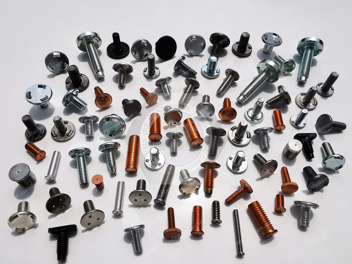
A qualified OEM supplier should be evaluated on more than unit price.
Projection geometry is directly related to welding behavior.
The supplier should have a controlled process for maintaining the dimensions defined by the approved drawing.
Material should be traceable according to the agreed customer requirements.
Where material certification is required, the supplier should provide documentation appropriate to the specified material and application.
The threaded shank must meet the applicable drawing and thread specification.
Important considerations include:
Thread size
Pitch
Thread tolerance/class
Thread cleanliness
Burr control
Mating compatibility
High-volume production may require the stud to be compatible with:
Bowl feeders
Linear feeders
Robotic pick-and-place systems
Welding automation
Vision inspection
Part geometry and packaging should therefore be reviewed together.
Packaging should prevent:
Thread damage
Excessive part-to-part deformation
Contamination
Corrosion during transportation
Feeding problems caused by unsuitable bulk packaging
The packaging specification should reflect the customer's production method.
Projection weld studs may be specified with reference to international standards depending on their design and welding method.
Relevant standards may include ISO 13918 for welding studs and related welding-stud terminology and requirements where applicable.
Other fastener standards may apply to particular dimensions, materials, or mechanical-property requirements.
However, a standard reference should never be interpreted as automatic compliance with every requirement of a customer's application.
The controlled engineering document should define:
Fastener geometry
Thread specification
Material
Surface treatment
Welding interface
Dimensional tolerances
Inspection requirements
Applicable standards
For OEM programs, the approved drawing and technical specification remain the primary references.
Projection height, edge distance, sheet thickness, welding current, force, and time should not be copied from a generic table without validating the actual application.
Projection count alone does not determine weld performance.
A continuous welding feature does not automatically provide a pressure-rated or IP-rated seal.
Coatings and contamination can significantly affect resistance welding behavior.
The stud should be selected together with the substrate and production welding system.
Joint performance requirements should come from the actual application specification or validated engineering test program.
Steel, stainless steel, coated steel, and other substrates can behave differently during resistance welding.
A practical OEM selection sequence is:
Step 1 — Define the thread
Specify metric or inch thread, size, pitch, and applicable thread requirements.
Step 2 — Define the substrate
Identify the material, thickness, coating, and local component geometry.
Step 3 — Define the welding process
Confirm whether resistance projection welding is available and determine the electrode and tooling arrangement.
Step 4 — Select the stud geometry
Review head diameter, head thickness, projection design, stud length, and locating features.
Step 5 — Review DFM
Check edge distance, nearby holes, formed features, electrode access, stud orientation, and assembly stack-up.
Step 6 — Define surface treatment
Select the required material and finish based on corrosion, welding, assembly, and customer requirements.
Step 7 — Validate the joint
Perform application-specific welding trials and mechanical validation before mass production.
For an accurate quotation and engineering review, provide:
2D engineering drawing
3D CAD model where available
Thread specification
Stud dimensions
Head geometry
Projection configuration
Stud material
Sheet material
Sheet thickness
Hole or mounting geometry
Surface treatment
Welding process
Electrode/tooling information where available
Required mechanical performance
Inspection requirements
Annual quantity
Prototype quantity
Production schedule
Packaging requirements
Applicable standards
If the design is still under development, even incomplete information can be useful.
For example:
“M6 threaded weld stud + coated steel sheet + resistance projection welding + annual volume 500,000 pcs”
gives the supplier a starting point for an engineering review.
JUXIN FASTENERS provides weld fastener solutions for OEM sheet-metal and fabricated-component applications.
The product range can include:
Projection weld studs
Threaded weld studs
Flanged weld studs
Custom weld studs
Weld nuts
Weld pins
CD weld fasteners
Arc weld fasteners
Custom OEM fastening components
For custom projection weld studs, the design can be reviewed according to the customer's:
Thread
Stud dimensions
Head configuration
Projection geometry
Substrate
Welding process
Surface treatment
Production volume
Inspection requirements
The objective is to develop a fastener that works within the customer's actual manufacturing process rather than simply supplying a nominally similar catalog part.
Related solution areas include:
Weld Nuts Solutions
Projection Weld Nuts
Hexagonal Weld Nuts
Square Weld Nuts
Weld Studs Solutions
Weld Pins Solutions
CD Weld Fasteners
Arc Weld Fasteners
Automotive Fastening Solutions
EV Fastening Solutions
Electrical Equipment Fastening Solutions
Internal linking should connect the weld-stud engineering topic with the relevant product and industry solution pages so engineers
can move from technical selection → product configuration → application solution → OEM RFQ.
Projection weld studs create permanent male threaded attachment points on metallic sheet and fabricated components.
They are commonly integrated into automotive, electrical, industrial, appliance, and other OEM assemblies.
They are typically installed using resistance projection welding, where engineered projections on the stud concentrate current and welding force at defined contact points.
They can be suitable for thin-sheet applications, but the correct design depends on the stud geometry, sheet material, thickness, welding process, and required joint performance.
Not necessarily. Projection count is only one design variable. Weld formation depends on the complete fastener, substrate, electrode setup, and welding parameters.
Potentially, yes. However, the actual coating and surface condition must be considered during resistance-welding process development and validation.
Not automatically. A particular stud geometry may support a continuous welded interface, but sealing or pressure-tight performance must be specifically designed and validated at the assembly level.
Possible causes include inadequate weld formation, unsuitable welding parameters, surface contamination, projection variation, electrode-force problems,
or substrate-related limitations. Failure analysis should identify the actual mechanism before changing the process.
Yes. Custom stud dimensions, thread specifications, head configurations, projection geometry, materials, and other features can be developed according to OEM drawings and application requirements.
Provide the drawing, thread specification, stud dimensions, material, substrate, sheet thickness, welding process, surface condition, required performance, quantity, inspection requirements, and applicable standards.
The best projection weld stud is not necessarily the largest, strongest, or most complex design.
It is the design that provides the required threaded interface while remaining compatible with:
Substrate + welding process + component geometry + assembly sequence + production volume
Before approving a weld stud for production, engineers and procurement teams should confirm:
Thread requirements
Stud geometry
Projection configuration
Substrate material
Sheet thickness
Surface condition
Welding equipment
Electrode access
DFM requirements
Mechanical validation requirements
Inspection requirements
Production and packaging requirements
This system-level approach reduces the risk of selecting a fastener that looks correct on a drawing but becomes difficult to weld, feed, inspect, or assemble in production.
If you are developing a new sheet-metal component or need an alternative source for projection weld studs, JUXIN FASTENERS can review your application requirements.
Send your drawing, thread specification, substrate information, welding process, surface treatment, estimated volume, and required performance to:
JUXIN FASTENERS — Precision Fastening Solutions Since 2003
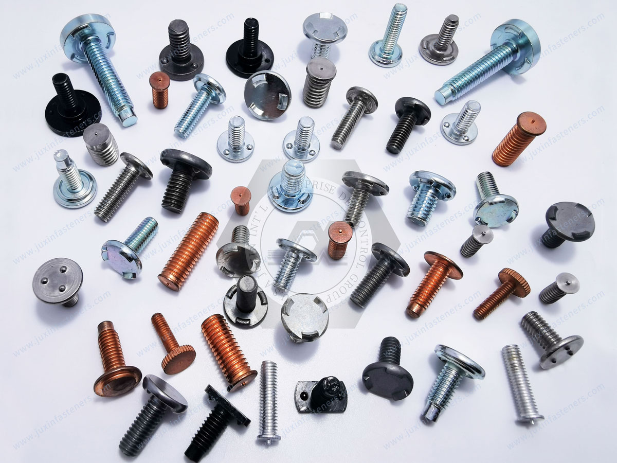
Product Packaging
Packaging Standard
At Juxin Fasteners, we apply standardized export packaging to ensure product protection, traceability, and compliance with international logistics requirements.
1. Standard Export Packaging
Unless otherwise specified, all products will be packed according to our factory standard export packaging, which includes:
Moisture-resistant inner protection
Poly bag or small box packing as required
Reinforced export cartons
Clear labeling with part number, specification, batch number, and quantity
Palletizing for sea or air shipment when necessary
Our standard packaging is designed to ensure safe transportation, efficient warehousing, and long-distance international shipping.
2. Customized Packaging Options
We also provide customized packaging solutions according to customer requirements, including but not limited to:
Private labeling
Customized barcodes
Specific carton dimensions
Retail packaging
Special pallet configuration
Customer-specific marking and identification
So that you know, customized packaging may involve additional costs and extended lead time depending on the complexity of the requirements.
3. Compliance & Quality Assurance
All packaging processes are controlled under our ISO 9001 quality management system to ensure consistency, traceability, and product integrity throughout the supply chain.
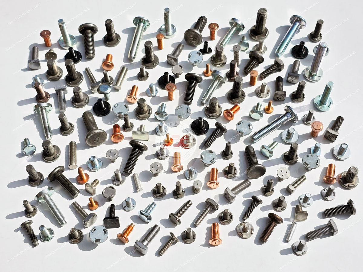
Product Pictures
Contact Us
Tel.:
+86 020 8621 0320
+86 020 3121 6067
E-mail:
Technical Support:
Navigation
SEND INQUIREY