Call Us
+86 136 6007 9809
Call Us
+86 136 6007 9809

Why do projection weld studs fail under push-out or pull-out loads?
Weld stud failures occur when the applied load exceeds the capacity of the welded joint, the weld stud itself, or the surrounding sheet metal.
The actual failure mode depends on the stud geometry, weld configuration, parent material, sheet thickness, weld quality, loading direction, and the way the load is transferred into the assembly.
Product Specification
Why do projection weld studs fail under push-out or pull-out loads?
Weld stud failures occur when the applied load exceeds the capacity of the welded joint, the weld stud itself, or the surrounding sheet metal.
The actual failure mode depends on the stud geometry, weld configuration, parent material, sheet thickness, weld quality, loading direction, and the way the load is transferred into the assembly.
Under axial tensile loading, a properly welded stud may ultimately fail through deformation or tearing of the surrounding parent sheet, depending on the joint design and material combination.
A defective weld may instead separate through the weld interface because the effective bonded area is insufficient.
Under push-out or compressive loading, failure can occur through local deformation of the sheet, separation of the welded interface, or movement of the stud relative to the substrate.
The precise failure mechanism should therefore be established through application-specific testing rather than assumed from the loading direction alone.
For OEM engineers, the important question is not simply whether a weld stud has a high nominal strength. The more useful engineering question is:
Where is the weakest link in the complete stud-to-sheet load path?
That load path can include the weld interface, weld nugget, stud base, parent sheet, local sheet geometry, and the surrounding assembly.
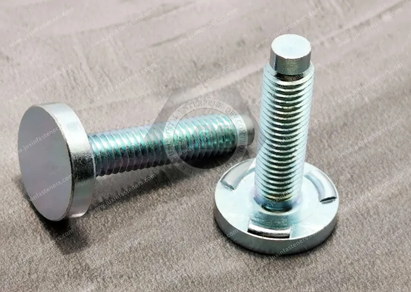
JUXIN FASTENERS supplies projection weld studs for industrial fastening applications and supports OEM evaluation of stud geometry, substrate material, welding conditions, and application requirements.

Pull-out failure occurs when a tensile load acts approximately along the axis of the weld stud and the joint can no longer transfer that load safely.
A properly designed and welded joint does not necessarily fail at the weld interface. Depending on the sheet material and thickness, stud geometry, weld configuration,
and applied load, the surrounding parent metal may deform or tear before complete separation of the weld.
Typical failure paths can include:
Parent metal tear-out: The sheet around the welded stud deforms and tears while the weld connection remains comparatively intact.
Weld interface separation: The welded area separates because the effective weld bond is insufficient for the applied load.
Stud or stud-base failure: The fastener itself deforms or fractures when the stud or its welded section becomes the limiting component.
Local sheet deformation: The sheet bends, dishes, or plastically deforms around the stud before final failure.
This distinction is important during quality analysis. A pull-out test that records only the peak force does not provide the complete engineering picture.
The failure mode and fracture location should also be documented.
Push-out loading applies an axial force in the opposite direction and can occur during assembly, component installation, bracket loading, or service.
Possible failure mechanisms include:
separation of the weld interface;
local deformation of the parent sheet;
displacement or bending of the stud;
failure of the surrounding sheet structure;
insufficient weld formation caused by unsuitable welding conditions.
A common mistake is to treat push-out strength as a fixed property of the weld stud itself. In reality, the measured result is a property of the complete stud-sheet-welding system.
Sheet thickness, material strength, surface condition, projection geometry, electrode conditions, welding current, welding time, electrode force, and assembly configuration can all influence the final result.
Weld studs are not always loaded purely in tension or compression.
A bracket mounted to a welded stud can introduce:
transverse shear;
bending moment;
eccentric loading;
cyclic loading;
combined tension and shear.
For example, when the applied force is offset from the sheet surface, the stud can experience a bending moment in addition to axial loading.
This can increase local stress at the stud base and change the eventual failure mode.
For structural applications, engineers should therefore evaluate the actual load path rather than relying only on a single axial pull-out value.
The capacity of a weld stud connection is influenced by several interacting variables.
The stud diameter, base configuration, weld projection arrangement, flange geometry, and overall dimensions influence how force is transferred from the stud into the welded region and parent sheet.
A larger stud does not automatically produce a stronger joint. The weld area and surrounding sheet must be capable of transferring the corresponding load.
Sheet thickness is a major factor because the parent metal may become the limiting component of the connection.
When the sheet is relatively thin compared with the stud geometry, tensile or lateral loading can produce localized deformation or tearing around the stud.
For this reason, engineers should evaluate the stud-to-sheet combination, not specify a weld stud independently from the substrate.
Steel grades, stainless steels, coated materials, and other conductive substrates can respond differently during resistance welding.
Electrical resistance, thermal conductivity, surface condition, material strength, and metallurgical behavior all influence the welding process and the resulting joint.
Material selection should therefore be validated against the actual welding process and production conditions.
Projection weld studs rely on controlled contact geometry to concentrate electrical current and mechanical force at the intended welding locations.
If the projection geometry or welding conditions are unsuitable, the resulting weld may have inadequate fusion or inconsistent nugget formation.
Potential causes include:
insufficient welding energy;
excessive welding energy;
inappropriate electrode force;
unstable electrical contact;
poor electrode alignment;
inconsistent projection dimensions;
contamination at the weld interface;
unsuitable material combinations.
The objective is not simply to maximize welding energy. The objective is to establish a stable process window that produces consistent weld formation without damaging the surrounding sheet.
A weld stud may fail prematurely when the welding process does not generate sufficient fusion at the intended weld locations.
Possible causes include incorrect welding current, welding time, electrode force, or unstable electrical contact.
The correct parameters must be established according to the actual stud, material, sheet thickness, equipment, electrode configuration, and production conditions.
There is no single universal current, time, or force value that can safely be applied to every weld stud application.
Too much welding energy can also create problems.
Depending on the material combination and process conditions, excessive energy may result in:
expulsion or weld spatter;
excessive indentation;
localized sheet damage;
excessive heat input;
inconsistent nugget formation;
distortion of thin sheet.
A larger weld appearance does not automatically mean a stronger production joint. Process stability and the resulting failure mode are more meaningful indicators.
Electrode alignment affects how mechanical force and electrical current are distributed during welding.
If the electrode setup is not properly aligned, some projections may receive different mechanical or electrical conditions from others.
This can contribute to inconsistent projection collapse and weld formation.
Production equipment should therefore be checked for:
electrode alignment;
electrode condition;
contact surface condition;
force consistency;
fixture stability;
stud positioning.
Exact dimensional tolerances should be established from the welding equipment, fastener design, and validated manufacturing process rather than treated as universal values.
Oil, scale, oxides, coatings, dirt, or other surface conditions can alter electrical contact and heat generation at the weld interface.
This is especially important when coated or pre-finished materials are being considered.
The surface condition of both the stud and parent sheet should be evaluated as part of process qualification.
If a coating is present, its compatibility with the resistance welding process must be confirmed rather than assumed.
Even when the weld itself is acceptable, incorrect stud positioning can create an unfavorable structural load path.
An offset stud can introduce eccentric loading into a bracket. A stud placed too close to an edge can also increase the risk of local sheet deformation or tear-out.
Therefore, stud location should be reviewed together with:
edge distance;
bracket geometry;
hole location;
applied load;
load direction;
sheet thickness;
surrounding reinforcement.
The most reliable way to establish weld stud performance is application-specific testing.
A destructive axial pull test applies tensile force along the stud axis until the joint or fastener reaches failure.
The test should record:
peak load;
displacement;
failure location;
failure mode;
visible weld condition;
parent sheet deformation.
The failure mode is particularly important.
For example, parent-sheet tearing may indicate that the weld connection is stronger than the surrounding sheet under the specific test configuration.
A clean separation at the weld interface may indicate insufficient weld formation or an unsuitable process condition.
A push-out test applies compressive axial loading to the stud or its associated component.
The fixture must reproduce the intended load path as closely as practical. Otherwise, the test result may not represent actual production conditions.
The test should again document both the peak load and the physical failure mechanism.
When the final application introduces lateral loading or bending, an axial pull test alone may not be sufficient.
Testing may need to evaluate:
direct shear;
bending moment;
combined tensile and shear loading;
cyclic loading;
assembly-induced loading.
The appropriate test method should be selected according to the actual application requirements and relevant customer or industry specifications.
For process development and quality investigation, metallographic cross-sections can provide valuable information about weld formation.
A cross-section may help identify:
weld nugget development;
fusion characteristics;
internal discontinuities;
excessive indentation;
heat-affected regions;
inconsistent projection collapse.
Cross-sectional analysis is especially useful when a destructive load test identifies an unexpected failure mode and the engineering team needs to determine why it occurred.
One of the most important principles in weld stud design is to avoid treating a single pull-out or push-out number as universally applicable.
The allowable capacity of a weld stud joint depends on the complete application.
Engineers should consider:
Applied load → stud geometry → weld configuration → parent sheet → surrounding structure → actual failure mode
Instead of applying an arbitrary universal safety multiplier, the design team should establish the required design margin according to the applicable engineering standard,
customer specification, regulatory requirement, loading condition, and consequence of failure.
The following factors should be considered during load assessment:
maximum expected service load;
static versus cyclic loading;
load direction;
eccentricity;
environmental conditions;
temperature exposure;
material variation;
manufacturing variation;
required design safety factor;
applicable industry or customer requirements.
For critical structural applications, the required design margin should be defined by the responsible engineering organization rather than by a generic rule applied to every weld stud.
A robust weld stud design should connect fastener selection, substrate design, welding process development, and validation testing.
Before production release, confirm:
stud material;
stud geometry;
parent sheet material;
parent sheet thickness;
surface condition;
welding configuration;
electrode configuration;
expected loading conditions.
The welding process should be developed around the actual production combination rather than copied from an unrelated application.
Key process variables include:
welding current;
weld time;
electrode force;
squeeze and hold conditions;
electrode alignment;
electrode condition;
projection geometry;
surface condition.
The goal is a repeatable process window rather than a single machine setting that works only under ideal laboratory conditions.
A production qualification program should not rely only on whether a sample exceeds a target force.
Record how the sample failed.
If the parent metal consistently fails before the weld interface under the specified test condition, that provides different engineering information from a joint that repeatedly separates through the weld.
Failure-mode records are therefore valuable for:
process qualification;
supplier quality management;
root-cause analysis;
production audits;
engineering change validation.
Even a correctly developed weld process can become unstable if production conditions change.
Quality monitoring may include:
incoming material verification;
stud dimensional inspection;
projection consistency;
electrode condition checks;
welding parameter monitoring;
destructive sample testing;
failure-mode analysis.
The inspection frequency and acceptance criteria should be established according to the application risk and customer requirements.
For procurement teams, weld stud sourcing should go beyond purchasing the correct thread size.
An OEM RFQ should ideally identify:
stud diameter and thread specification;
overall length;
base or flange configuration;
parent sheet material;
parent sheet thickness;
coating or surface condition;
welding process;
expected production volume;
application loading;
required inspection;
applicable drawings or standards;
packaging and traceability requirements.
When a weld stud is part of a safety-critical or structurally important assembly, the supplier should understand the actual application rather than quoting solely from a generic catalog description.
JUXIN FASTENERS can support OEM sourcing discussions around weld stud configuration, substrate compatibility, custom dimensions, and application-specific requirements.
Weld Fasteners Solutions: JUXIN FASTENERS weld fastener solutions for industrial applications.
Projection Weld Studs: Weld stud configurations for resistance welding applications.
Projection Welding Process Optimization: Engineering considerations for current, force, time, projection geometry, and joint design.
Weld Nut Spin Failure Analysis: Failure analysis for rotational failure of resistance-welded nuts.
Weld Fastener Selection: Engineering comparison of weld fasteners with alternative threaded fastening technologies.
The most reliable approach is application-specific destructive axial pull testing using a controlled fixture and a calibrated test system.
Record both the peak load and the failure mode. The resulting data should be evaluated against the applicable engineering requirement rather than compared with an assumed universal weld stud strength value.
Possible causes include insufficient weld formation, unsuitable welding parameters, inconsistent projection geometry, poor electrical contact, surface contamination,
inadequate parent-sheet capacity, unfavorable stud location, or excessive applied loading.
Root-cause analysis should distinguish between weld-interface failure, fastener failure, and parent-metal failure.
No. Increasing stud size does not automatically increase the capacity of the complete joint.
The parent sheet, weld configuration, projection geometry, load path, and surrounding structure must all be capable of supporting the required load.
No. Stud diameter alone is not sufficient to establish the capacity of a welded stud joint.
Engineering evaluation should include the stud geometry, weld configuration, substrate material and thickness, loading direction, weld quality, and relevant design requirements.
Start by identifying the actual failure mechanism. Then review the stud geometry, substrate, welding current, weld time, electrode force, electrode alignment, surface condition, and production variation.
Validate the corrective action with destructive testing and failure-mode analysis before production release.
Need to investigate weld stud push-out, pull-out, or weld-interface failures in your production assembly?
Send JUXIN FASTENERS your stud drawing, parent-sheet material and thickness, welding process information, application loading requirements, and annual production volume.
Email: info@juxinfasteners.com
JUXIN FASTENERS provides OEM weld studs and engineering support for application-specific fastener selection, weld process evaluation, sample testing, and production sourcing.
For engineering review, providing the actual stud drawing and substrate specification allows the fastening solution to be evaluated as a complete joint rather than as an isolated fastener.
Product Packaging
Packaging Standard
At Juxin Fasteners, we apply standardized export packaging to ensure product protection, traceability, and compliance with international logistics requirements.
1. Standard Export Packaging
Unless otherwise specified, all products will be packed according to our factory standard export packaging, which includes:
Moisture-resistant inner protection
Poly bag or small box packing as required
Reinforced export cartons
Clear labeling with part number, specification, batch number, and quantity
Palletizing for sea or air shipment when necessary
Our standard packaging is designed to ensure safe transportation, efficient warehousing, and long-distance international shipping.
2. Customized Packaging Options
We also provide customized packaging solutions according to customer requirements, including but not limited to:
Private labeling
Customized barcodes
Specific carton dimensions
Retail packaging
Special pallet configuration
Customer-specific marking and identification
So that you know, customized packaging may involve additional costs and extended lead time depending on the complexity of the requirements.
3. Compliance & Quality Assurance
All packaging processes are controlled under our ISO 9001 quality management system to ensure consistency, traceability, and product integrity throughout the supply chain.
Product Pictures
Contact Us
Tel.:
+86 020 8621 0320
+86 020 3121 6067
E-mail:
Technical Support:
Navigation
SEND INQUIREY