Call Us
+86 136 6007 9809
Call Us
+86 136 6007 9809

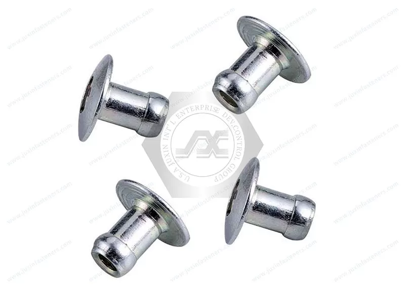
High-speed blind rivets, also called speed rivets, are designed for repetitive single-sided fastening in OEM manufacturing.
Dome and countersunk head options support different assembly geometries, while compatible speed riveting systems can reduce manual loading and improve production throughput.
JUXIN FASTENERS lists brass, steel, stainless steel and aluminum material options.
Explore installation principles, tooling compatibility, engineering selection, industrial applications and drawing-based RFQ requirements.
Product Specification
High-Speed Blind Rivets for Automated OEM Assembly
High-speed blind rivets, commonly referred to as speed rivets, are specialized fastening components designed for rapid, repetitive installation in industrial manufacturing.
Unlike conventional break-mandrel blind rivets that are individually loaded into a riveting tool,
many speed riveting systems use preloaded or collated fasteners and a reusable installation mandrel to support successive fastening cycles.
JUXIN FASTENERS supplies high-speed blind riveting components for OEM manufacturing applications requiring efficient single-sided assembly,
controlled joint formation and compatibility with appropriate production tooling.
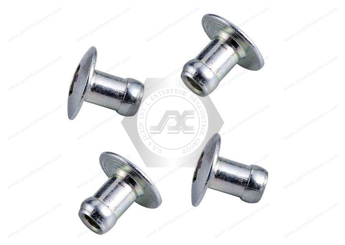
The product range is described with dome head and countersunk head configurations and material options including aluminum, steel, stainless steel and brass.
Specific material, head style, dimensional and installation combinations must be confirmed against the applicable engineering drawings.
Speed rivets are particularly relevant to production engineers and OEM manufacturers evaluating repetitive fastening operations, assembly cycle times, installation accessibility and process consistency.
Product Overview
Product Name: High-Speed Blind Rivets
Alternative Engineering Terms: Speed Rivets, Speed Blind Rivets, High-Speed Riveting Fasteners
Product Category: Speed Riveting / Blind Fastening Components
Listed Materials:
Aluminum
Steel
Stainless Steel
Brass
Head Configurations:
Dome Head
Countersunk Head
Installation Concept: Repetitive Blind-Side Riveting
Typical System Characteristics:
Single-sided installation access.
Compatible repetitive rivet feeding.
Controlled mechanical deformation.
Reduced individual fastener handling.
Potential integration with semi-automated or automated production equipment.
No conventional broken mandrel stem remaining in the joint when the applicable speed fastening system is correctly used.
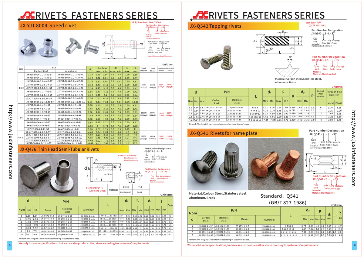
Available diameters, lengths, grip ranges, head dimensions, material grades and tooling requirements must be confirmed from the product specification drawings.
Custom engineering requirements may be evaluated according to customer drawings and assembly conditions.
What Are Speed Blind Rivets?
Speed blind rivets are fastening components developed for repetitive installation using a compatible speed riveting system.
In a typical reusable-mandrel system, multiple rivets are preloaded in a magazine or collated strip.
The installation tool advances the next rivet into position and uses the mandrel to deform the rivet body during setting.
The mandrel is part of the installation process rather than a conventional disposable break stem retained inside each finished joint.
This distinction is important.
Speed rivets should not be confused with ordinary break-mandrel blind rivets, drive rivets or structural locking-bolt systems.
Their fastening performance depends on the particular rivet geometry, material, tooling and installation method.
Speed Rivets vs. Conventional Blind Pop Rivets
Conventional Break-Mandrel Blind Rivets
A conventional blind rivet generally consists of a rivet body and an individual mandrel.
During installation, the tool pulls the mandrel to deform the rivet body.
The mandrel breaks at a designed location, leaving the installed rivet and potentially a retained mandrel portion.
Conventional blind rivets can be suitable for many industrial assembly operations, but manual processes may require individual rivet loading and spent-mandrel handling.
High-Speed Blind Rivets
Speed rivets are designed for repetitive installation with compatible tooling.
Depending on the system, the rivets may be supplied preloaded or collated for sequential feeding.
Advantages may include:
Reduced manual fastener loading.
Faster repetitive assembly.
Improved operator workflow.
More consistent fastener presentation.
Reduced disposable mandrel waste.
Suitability for integration into production workstations.
Actual productivity improvements depend on the equipment, rivet configuration, workpiece handling and production process.
Dome Head vs. Countersunk Head Speed Rivets
The manufactured head profile must match the mechanical and dimensional requirements of the assembly.
Dome Head Speed Rivets
Dome head rivets have a raised head profile with a bearing surface designed to seat against the workpiece.
They may be suitable for:
General industrial panel assembly.
Metal component fastening.
Equipment brackets.
Assemblies where a protruding head is acceptable.
Engineering considerations include head diameter, head height, available clearance and bearing pressure.
Countersunk Head Speed Rivets
Countersunk head rivets have a tapered head intended to fit a corresponding countersunk hole.
They may be suitable where reduced head projection or a flush installation is required.
Engineering considerations include:
Countersink diameter.
Countersink angle.
Remaining material thickness.
Head seating.
Hole alignment.
Local stress and deformation.
A countersunk head will not automatically sit flush unless the countersink geometry matches the rivet head.
The countersink angle must be confirmed from the actual drawing.
Material Selection for High-Speed Blind Rivets
Material selection affects forming behavior, corrosion performance, installation force and joint characteristics.
Aluminum Speed Rivets
Aluminum may be suitable for selected lightweight assemblies and applications where its forming behavior and corrosion characteristics meet the design requirements.
The alloy and temper must be verified for the intended joint.
Steel Speed Rivets
Steel may be considered where the specified mechanical properties and installation requirements favor a steel fastener.
Strength, hardness, coating and corrosion protection must be evaluated against the approved specification.
Stainless Steel Speed Rivets
Stainless steel may be selected where corrosion resistance and compatible mechanical properties are required.
The stainless steel grade, material condition and setting-tool capability must be confirmed.
Brass Speed Rivets
Brass may be considered for specialized assemblies where its material characteristics are relevant.
The actual brass grade, forming characteristics and available rivet dimensions must be verified before specifying the component.
Not every material is necessarily available in every diameter, head style or grip range.
Material availability should be confirmed for each OEM project.
How a High-Speed Riveting System Works
A typical speed riveting process uses a compatible installation tool and sequentially presented fasteners.
Step 1: Prepare the Workpieces
Confirm the material thickness, hole diameter, hole position and joint configuration.
Remove unacceptable burrs or defects that could interfere with insertion and installation.
Step 2: Load the Riveting System
Prepare the compatible rivet magazine, strip or feeding system according to the equipment instructions.
The rivet geometry and feeding arrangement must match the selected installation tool.
Step 3: Position the Tool
Align the rivet and tool with the prepared installation hole.
Maintain suitable access and support for the workpiece.
Step 4: Set the Rivet
The tool applies the required installation action to deform the rivet body and create the retaining geometry on the blind side.
Depending on the rivet design, the body may expand radially and form a controlled bulge or other retaining profile.
Step 5: Advance the Next Fastener
The tool or feeding mechanism prepares the next rivet for installation.
This reduces the need to manually load each fastener.
Step 6: Verify the Joint
Inspect the installed rivet for proper seating, deformation and any application-specific acceptance criteria.
The installation sequence and parameters must be verified for the actual rivet and equipment combination.
High-Speed Assembly and Production Throughput
Speed riveting systems are designed to reduce repetitive manual handling and improve assembly efficiency.
Published industrial speed riveting systems demonstrate that installation cycles below two seconds and production rates approaching 60 rivets per minute can be achievable under suitable conditions.
These values describe examples of system-level performance. They are not guaranteed installation rates for every rivet, tool or JUXIN production application.
Actual throughput depends on:
Rivet feeding configuration.
Installation tool performance.
Workpiece loading and unloading.
Hole alignment.
Operator movement.
Fixture design.
Assembly accessibility.
Rivet material and diameter.
Inspection requirements.
Production-line integration.
OEM production managers should evaluate the complete workstation cycle rather than relying only on the rivet setting time.
Radial Expansion and Joint Formation
Certain speed rivet designs expand radially during installation.
This deformation can improve contact with the installation hole and contribute to mechanical retention.
Other designs use a bulged or specially formed blind-side profile.
The appropriate deformation depends on:
Rivet body geometry.
Material condition.
Hole diameter.
Grip thickness.
Installation mandrel geometry.
Tool setting parameters.
The installed joint must be validated for its intended mechanical requirements.
Radial expansion alone does not guarantee a particular shear strength, vibration resistance or torque performance.
Industrial Applications and Engineering Solutions
High-speed blind riveting is particularly relevant where OEM manufacturers repeatedly install similar fasteners in production.
The following applications represent potential engineering uses requiring confirmation of the selected rivet design and installation process.
1. Automotive Component Manufacturing
Automotive OEM and Tier-1/Tier-2 manufacturers often require repetitive fastening of brackets, panels and non-threaded subassemblies.
Potential applications include:
Interior component assemblies.
Non-safety-critical brackets.
Selected sheet-metal components.
Plastic-to-metal subassemblies.
Equipment and fixture components.
Engineering challenge:
Production lines must balance assembly speed, joint repeatability and material protection.
Engineering solution:
A compatible speed riveting system can reduce manual rivet loading and support repeatable fastening operations where one-sided access is required.
Key engineering considerations:
Component thickness.
Hole diameter and tolerance.
Mixed-material compatibility.
Installation access.
Joint strength requirements.
Vibration exposure.
Tooling repeatability.
Process inspection.
Applications involving safety-critical or structural automotive components require separate engineering validation and any applicable customer approval.
2. Electrical and Electronic Equipment Manufacturing
Electrical and electronic equipment manufacturers may use speed riveting in repeated mechanical assembly operations.
Potential applications include:
Electronic equipment chassis.
Metal enclosure assemblies.
Equipment brackets.
Lighting housings.
Non-threaded component retention.
Engineering challenge:
Assemblies may involve compact components, sensitive surfaces and limited installation access.
Engineering solution:
Speed riveting may reduce individual fastener handling and provide controlled mechanical fastening when the rivet geometry and tooling are compatible.
Important considerations:
Component clearance.
Tool accessibility.
Electrical isolation requirements.
Installation force.
Surface protection.
Conductive debris control.
Joint inspection.
No electrical grounding, insulation or current-carrying function should be assumed without specific testing.
3. Home Appliance and HVAC Equipment Manufacturing
Home appliance and HVAC equipment manufacturers may require high-volume joining of thin metal panels and small fabricated components.
Potential applications include:
Appliance housing subassemblies.
Sheet-metal brackets.
Internal support components.
Equipment covers.
Selected lightweight panel assemblies.
Engineering challenge:
Repetitive fastening operations can create labor demand, assembly variation and potential surface damage.
Engineering solution:
Compatible speed rivets may support more efficient assembly where repeated fastener placement and single-sided access are required.
Key considerations:
Coated or painted surface protection.
Material thickness.
Hole alignment.
Joint retention.
Equipment access.
Production throughput.
Quality inspection.
Surface damage cannot be ruled out solely because a speed rivet is used. Tooling, support and process validation remain necessary.
4. Industrial Equipment and Light Metal Fabrication
Industrial equipment manufacturers may use speed riveting for repeated joining operations in suitable metal, plastic or composite subassemblies.
Potential applications include:
Equipment panels.
Fabricated brackets.
Lightweight structures.
Mechanical covers.
Repetitive production assemblies.
Engineering challenge:
The manufacturing process may require a consistent joint while minimizing operator handling and assembly interruptions.
Engineering solution:
A suitable speed riveting system can be evaluated as part of a production cell or semi-automated workstation.
Engineering review should address:
Static and dynamic loads.
Shear and tensile requirements.
Hole preparation.
Grip thickness.
Material compatibility.
Installation equipment.
Workstation ergonomics.
Inspection criteria.
The rivet must not be treated as a structural fastener without appropriate design verification.
Engineering Considerations for Mixed-Material Assemblies
Speed rivets may be considered for joining selected combinations of:
Metal to metal.
Metal to plastic.
Metal to composite.
Laminated components.
Coated or painted materials.
However, the joint must be designed for the specific substrates.
Important factors include:
Material stiffness.
Local compression.
Hole deformation.
Differential thermal expansion.
Galvanic corrosion.
Surface finish.
Vibration.
Creep or relaxation.
Risk of cracking or delamination.
Soft or brittle substrates may require specialized rivet geometries or additional bearing support.
A general speed rivet should not automatically be considered suitable for every composite or plastic application.
Tooling Compatibility and Automated Feeding
Speed rivets are components of a fastening system.
The rivet, mandrel, nosepiece, feeding magazine and installation tool must be compatible.
Before selecting a speed rivet for an OEM production line, confirm:
Rivet diameter.
Rivet length.
Grip range.
Head configuration.
Body geometry.
Mandrel compatibility.
Feeding format.
Tool stroke and setting capability.
Available installation space.
Production cycle requirements.
Compatibility with any particular branded tool must not be assumed without verification.
For automated applications, production engineers should also consider:
Fastener feeding consistency.
Jam prevention.
Part orientation.
Sensor and process monitoring.
Tool maintenance.
Magazine changeover.
Error detection.
Installation traceability where required.
The complete fastening process should be validated before production release.
Common Speed Riveting Problems and Prevention
Problem: Incomplete Rivet Setting
Possible causes:
Incorrect tool parameters.
Incompatible mandrel geometry.
Unsuitable rivet length.
Excessive assembly thickness.
Recommended action:
Verify the rivet-tool combination and approved grip range.
Problem: Poor Hole Filling
Possible causes:
Oversized installation hole.
Incorrect rivet diameter.
Insufficient radial deformation.
Incompatible body geometry.
Recommended action:
Review hole tolerances and the installed rivet profile.
Problem: Surface Damage
Possible causes:
Excessive tool force.
Poor nosepiece contact.
Inadequate workpiece support.
Tool misalignment.
Recommended action:
Review tooling, fixtures and surface protection requirements.
Problem: Inconsistent Fastener Feeding
Possible causes:
Incorrect magazine format.
Dimensional variation.
Damaged collated strip.
Tool contamination or wear.
Recommended action:
Verify the feeding system and component dimensional consistency.
Problem: Joint Loosening Under Vibration
Possible causes:
Insufficient joint retention.
Incorrect rivet geometry.
Inappropriate material selection.
Loading beyond the validated joint capability.
Recommended action:
Review the assembly design and conduct appropriate vibration or fatigue validation.
Problem: Cracking or Damage in Soft Materials
Possible causes:
Excessive installation force.
Inadequate bearing area.
Unsuitable rivet deformation.
Local material weakness.
Recommended action:
Evaluate a suitable rivet geometry and installation process for the substrate.
Quality Control for OEM Speed Rivets
Quality requirements should be defined by the approved engineering drawing and installation process.
Dimensional Inspection
Relevant dimensions may include:
Body diameter.
Body length.
Head diameter.
Head height.
Grip range.
Critical forming geometry.
Applicable tolerances.
Material Verification
Confirm the specified aluminum, steel, stainless steel or brass grade where required.
Visual Inspection
Check for:
Cracks.
Burrs.
Surface defects.
Deformed heads.
Inconsistent body geometry.
Damage affecting feeding or installation.
Installation Process Validation
Verify the compatibility of the rivet with the selected tooling and assembly conditions.
Functional Testing
Depending on the application, testing may include:
Shear performance.
Tensile or pull-out resistance.
Vibration performance.
Installed joint stability.
Surface condition.
Process repeatability.
These are potential customer-defined validation activities, not claims that every test is routinely performed on every JUXIN product.
Acceptance criteria and documentation must be established for each OEM manufacturing program.
OEM Production Engineering and Total Assembly Cost
The value of speed riveting should be evaluated at the assembly-process level.
For production managers, relevant factors include:
Rivets installed per production cycle.
Operator handling time.
Tool reloading frequency.
Workstation uptime.
Fastener feeding reliability.
Assembly rework.
Scrap and material damage.
Tool maintenance.
Process inspection.
Overall equipment integration.
A faster individual setting operation does not automatically produce the same percentage improvement in complete line throughput.
The correct evaluation compares the entire manufacturing process before and after the proposed fastening change.
Custom Speed Rivets for OEM Manufacturing Projects
Custom speed riveting components may require changes to:
Body diameter.
Body length.
Head geometry.
Material specification.
Forming profile.
Grip range.
Surface finish.
Dimensional tolerances.
Feeding configuration.
Tool compatibility.
Any custom design must be assessed for manufacturing feasibility and the intended installation system.
Customers should provide drawings of the existing rivet and relevant installation details when requesting a replacement or modified component.
Frequently Asked Engineering Questions
What are speed rivets?
Speed rivets are specialized fasteners designed for repetitive installation using compatible speed riveting systems, often with preloaded or collated feeding arrangements.
Are speed rivets the same as ordinary blind pop rivets?
No. Conventional break-mandrel blind rivets typically use an individual mandrel that breaks during installation. Many speed riveting systems use a reusable installation mandrel and sequentially fed rivets.
Do speed rivets contain a mandrel?
The installed rivet may have no broken mandrel stem remaining in the joint, but the installation system can use a reusable mandrel to form the rivet.
Can speed rivets be installed from one side?
Yes, suitable speed riveting systems support blind-side installation when the assembly and tool access conditions are compatible.
Are speed rivets available with dome and countersunk heads?
The listed JUXIN product includes dome and countersunk head configurations.
Specific dimensions and material combinations must be confirmed.
Can speed rivets be installed at 60 rivets per minute?
Some industrial speed riveting systems report rates approaching 60 rivets per minute under suitable conditions.
Actual throughput depends on the selected equipment and complete assembly process.
Do speed rivets work in plastic and composite materials?
Certain speed rivet designs may be suitable for these materials, but substrate properties, hole geometry, forming behavior and joint requirements must be validated.
Do speed rivets prevent vibration loosening?
Suitable designs can provide vibration-resistant joints, but performance must be confirmed for the actual loading conditions and assembly.
Can speed rivets be used on painted panels?
They may be suitable when tooling and installation parameters protect the finished surface. Damage-free installation must be verified.
Are all speed rivets compatible with the same riveting tools?
No. Mandrel geometry, feeding format, rivet dimensions and tool capability must be checked for compatibility.
Can speed rivets be customized for OEM production?
Custom requirements can be evaluated from engineering drawings and installation specifications, subject to manufacturing and tooling feasibility.
What information is needed for an OEM speed rivet RFQ?
A product drawing, material specification, head type, diameter, length, grip range, assembly materials, installation equipment and annual production demand provide a useful basis for technical evaluation.
Request a Drawing-Based OEM Speed Rivet RFQ
JUXIN FASTENERS supports technical inquiries for high-speed blind rivets and custom fastening components used in repetitive industrial manufacturing.
For a new OEM assembly or an existing production component, please provide:
2D engineering drawing or 3D CAD file.
Required rivet material and grade.
Dome or countersunk head configuration.
Body diameter and length.
Grip range and installation hole dimensions.
Assembly materials and thickness.
Existing riveting tool or feeding-system information.
Required joint performance.
Quality and inspection specifications.
Prototype or initial production quantity.
Estimated annual demand.
Target project schedule.
Our team can review the supplied technical requirements and discuss the next steps for engineering clarification and quotation.
JUXIN FASTENERS
Website: https://www.juxinfasteners.com/
Email: info@juxinfasteners.com
Submit Your Engineering Drawings for an OEM High-Speed Blind Rivet RFQ.
Product Packaging
Packaging Standard
At Juxin Fasteners, we apply standardized export packaging to ensure product protection, traceability, and compliance with international logistics requirements.
1. Standard Export Packaging
Unless otherwise specified, all products will be packed according to our factory standard export packaging, which includes:
Moisture-resistant inner protection
Poly bag or small box packing as required
Reinforced export cartons
Clear labeling with part number, specification, batch number, and quantity
Palletizing for sea or air shipment when necessary
Our standard packaging is designed to ensure safe transportation, efficient warehousing, and long-distance international shipping.
2. Customized Packaging Options
We also provide customized packaging solutions according to customer requirements, including but not limited to:
Private labeling
Customized barcodes
Specific carton dimensions
Retail packaging
Special pallet configuration
Customer-specific marking and identification
So that you know, customized packaging may involve additional costs and extended lead time depending on the complexity of the requirements.
3. Compliance & Quality Assurance
All packaging processes are controlled under our ISO 9001 quality management system to ensure consistency, traceability, and product integrity throughout the supply chain.
Product Pictures
Contact Us
Tel.:
+86 020 8621 0320
+86 020 3121 6067
E-mail:
Technical Support:
Navigation
SEND INQUIREY