Call Us
+86 136 6007 9809
Call Us
+86 136 6007 9809

Printed circuit boards and electronic assemblies increasingly carry more than electronic components.
Modern PCB assemblies may also support heat sinks, busbars, shields, power modules, daughterboards, connectors, structural brackets, and enclosure interfaces.
Product Specification
Printed circuit boards and electronic assemblies increasingly carry more than electronic components.
Modern PCB assemblies may also support heat sinks, busbars, shields, power modules, daughterboards, connectors, structural brackets, and enclosure interfaces.
These mechanical loads create a fastening problem that cannot always be solved with conventional sheet-metal hardware.
Many printed circuit board laminates, glass-epoxy materials such as FR4, reinforced plastics,
and other relatively non-ductile substrates do not deform around a fastener in the same way as ductile sheet steel or aluminum.
A fastening system designed to depend on substantial host-material cold flow may therefore be unsuitable for the substrate or may require a different installation concept.
Broaching fasteners provide one such solution.
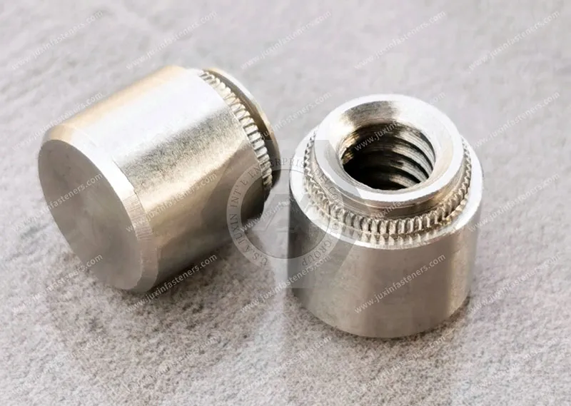
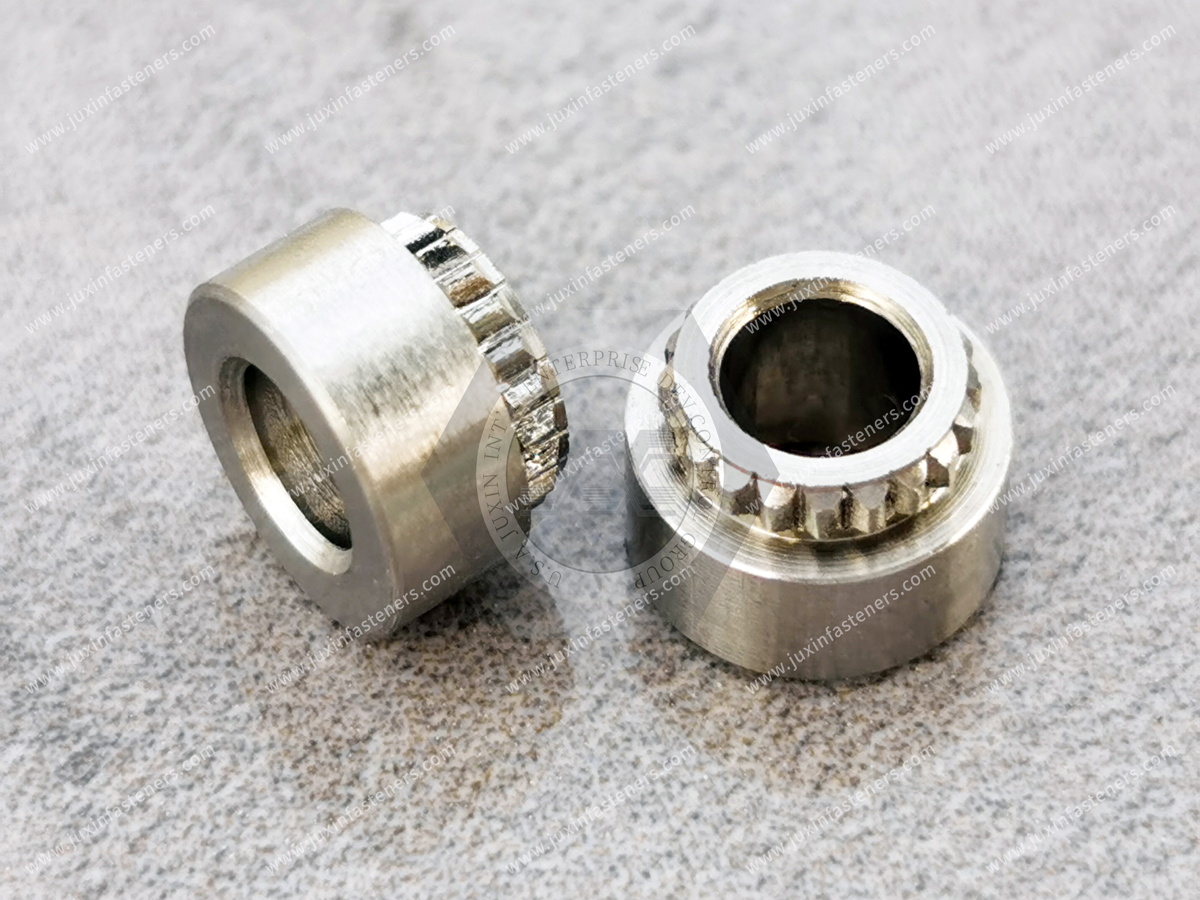
Broaching nuts, broaching studs, and broaching standoffs are designed to establish mechanically retained threaded features in suitable printed circuit boards and other non-ductile substrates.
Rather than relying primarily on the cold-flow mechanism associated with conventional self-clinching fasteners, the mounting feature engages the prepared hole wall to resist rotation and axial displacement.
For PCB design engineers, electronics packaging teams, manufacturing engineers, and procurement managers, however, selecting a broaching fastener involves much more than matching a thread size.
The substrate construction, board thickness, mounting-hole geometry, fastener shank design, edge distance, nearby copper features, installation method,
required torque-out and push-out performance, service environment, and assembly sequence all need to be evaluated together.
This guide explains how to approach that engineering and sourcing process.
A broaching fastener is a mechanically installed fastener designed to create a threaded or structural mounting feature in a suitable substrate through
controlled engagement between the fastener's mounting geometry and a prepared hole.
Common configurations include:
Broaching nuts for creating reusable female threads
Broaching studs for creating projecting male threaded attachment points
Broaching standoffs for supporting and spacing printed circuit boards or other components
Specialized PCB fastening hardware for electronic and electromechanical assemblies
The mounting section normally incorporates features designed to engage the hole wall as the fastener is pressed into position.
The exact tooth form, shank geometry, flange configuration, material, finish, installation hole, and dimensional relationship vary by fastener design.
For this reason, the correct installation hole should be determined from the applicable fastener specification or validated drawing rather than inferred only from the nominal thread size.
Traditional self-clinching fasteners are highly effective in suitable ductile sheet materials because their retention mechanism depends
on controlled displacement of the host material into a fastener undercut or retention feature.
FR4 and other glass-reinforced laminates behave differently.
They consist of resin systems, reinforcement layers, copper features, and—in multilayer PCBs—internal conductive structures.
They should therefore not be treated as thin sheet metal simply because both materials can be drilled or machined.
Applying an inappropriate installation geometry or excessive localized stress to a PCB may contribute to:
Resin cracking
Glass-fiber damage
Local delamination
Hole-wall damage
Surface damage around the mounting feature
Damage to nearby pads, traces, or internal planes
Insufficient fastener retention
Board distortion
Scrap after components have already been assembled
This is why broaching fasteners for PCBs should be treated as part of the mechanical design of the board rather than as generic hardware selected at the end of a project.
A typical broaching fastener combines a mounting shank, retention features, and a seating surface or flange.
During controlled press installation, the mounting features engage the prepared hole wall. Depending on the specific fastener design and substrate, this engagement can provide resistance to both rotational and axial movement.
The broaching features engage the substrate around the hole and resist rotation when a mating screw or nut is tightened or removed.
For engineers, this is usually evaluated through torque-out resistance.
Actual torque-out capability is not a universal property of the fastener alone. It depends on the complete fastener/substrate system,
including substrate type, laminate construction, board thickness, hole diameter and tolerance, mounting geometry, installation quality, fastener material, and substrate condition.
The installed fastener must also resist being displaced from the substrate during subsequent assembly or service.
Push-out or pull-out performance can become particularly important when technicians repeatedly install mating screws,
when relatively heavy components are mounted to the PCB, or when the assembly experiences vibration and handling loads.
These values should therefore be established using the specified fastener and representative production substrate.
The flange or shoulder provides a defined seating interface.
Correct seating is important because excessive installation travel or non-parallel pressing can concentrate load locally and damage a laminate even when the fastener itself is correctly selected.
The installation process is therefore part of the fastening system.
Broaching fasteners and self-clinching fasteners may appear similar, but they solve different material problems.
Self-clinching fasteners are generally intended for suitable ductile sheet materials. Their installation causes host material to flow into engineered retention features.
Broaching fasteners are designed for substrates where conventional sheet-metal cold-flow retention is not the appropriate mechanism.
That distinction matters when a product contains both a metal enclosure and PCB assemblies.
For example, one electronic enclosure may use self-clinching nuts in the sheet-metal chassis, self-clinching studs in brackets,
floating self-clinching nuts where assembly tolerance is required, and broaching standoffs or broaching nuts in suitable PCB or glass-epoxy structures.
The correct engineering question is therefore not simply:
Which fastener is stronger?
A more useful question is:
Which retention mechanism is compatible with the substrate, assembly process, service load, and maintenance requirement?
This substrate-first approach helps prevent a common specification error: selecting a familiar metal-panel fastener and attempting to transfer the same installation logic directly to a PCB or brittle substrate.
Surface-mount threaded hardware provides another method for adding mechanical attachment points to printed circuit boards.
The two technologies should not be treated as universally interchangeable.
Surface-mount hardware is integrated with a soldering process and may be attractive where automated placement and reflow integration are important.
Broaching hardware is mechanically installed and can be attractive where the assembly requires a press-installed mechanical attachment independent of the solder joint.
Key engineering differences include:
| Engineering Factor | Broaching Hardware | Surface-Mount Threaded Hardware |
|---|---|---|
| Retention principle | Mechanical engagement with prepared hole | Soldered attachment to PCB land pattern |
| PCB feature | Prepared mounting hole | Designed solder pad / land pattern |
| Installation process | Controlled mechanical pressing | SMT placement and reflow |
| Thermal-process dependency | Installation itself does not require solder reflow | Must be compatible with applicable soldering process |
| Layout impact | Hole, flange area and mechanical keep-out must be considered | Pad geometry and assembly keep-out must be considered |
| Validation focus | Hole tolerance, substrate condition, installation and mechanical retention | Solder-joint integrity, pad design, process compatibility and mechanical loading |
Neither solution is automatically superior.
The correct choice depends on PCB architecture, production process, loading direction, serviceability, available board area, mechanical performance requirements, and manufacturing strategy.
A broaching nut provides an internally threaded mounting point in a suitable PCB or non-ductile substrate.
This can be useful where the assembly requires repeated installation and removal of a screw without relying on threads formed directly in the board material.
Potential applications include enclosure attachment, board-to-bracket connections, removable electronic modules, shields and covers, power electronics assemblies,
instrumentation, telecommunications equipment, and industrial control electronics.
The thread specification should be selected according to the mating hardware and target market.
Depending on the design, this may include ISO metric threads or Unified inch threads.
Thread size alone, however, is insufficient for specifying the component. Procurement and engineering teams must also control the mounting geometry and substrate interface.
A broaching stud creates a fixed male threaded feature projecting from the board or substrate.
This can eliminate the need to hold a separate bolt during subsequent assembly and may simplify access where the reverse side becomes difficult to reach after installation.
Potential applications include mounting brackets, busbar interfaces, power electronics assemblies, electrical shields, structural supports, subassemblies, and terminal-related mechanical connections.
Where a stud carries electrical current or forms part of an electrical interface, mechanical fastening requirements must be evaluated separately from electrical requirements.
Fastener material, surface finish, contact resistance, current path, heat generation, insulation strategy, and applicable electrical design requirements may all influence the final component specification.
A mechanically secure stud should not automatically be assumed to provide the required electrical performance.
Broaching standoffs combine a mechanical mounting feature with a controlled spacing function.
They can be used to establish board-to-board or board-to-structure separation while also providing a threaded attachment point.
Applications can include:
Motherboard mounting
Daughterboard stacking
Controller assemblies
Communications equipment
Power supply modules
Semiconductor equipment
Industrial control systems
Medical electronic assemblies
For PCB designers, standoff height is not merely a hardware dimension.
It may affect connector alignment, airflow, component clearance, insulation distance, cable routing, heat-sink clearance, chassis packaging, service access, and board-to-board spacing.
The standoff therefore needs to be coordinated with the mechanical stack-up of the complete assembly.
One of the most important differences between ordinary hardware purchasing and PCB broaching fastener sourcing is that the installation hole is part of the product interface.
The mounting hole cannot be treated as an approximate clearance hole.
The correct hole diameter and tolerance depend on the selected broaching fastener design and substrate.
Too little engagement may reduce retention. Excessive interference may increase installation force and local substrate stress.
Consequently, PCB designers should establish the mounting-hole specification from verified fastener data and validate it with the actual board construction before production release.
Many broaching applications use a prepared non-plated mechanical hole, but this should not be turned into a universal rule for every broaching product or PCB design.
Whether a mounting hole should be NPTH (non-plated through hole) or another specified hole construction depends on the fastener design, supplier installation specification,
required electrical function, PCB fabrication process, final hole tolerance, and mechanical retention strategy.
If a hole is plated, the finished hole diameter, plating thickness, plating integrity, and mechanical interaction between the fastener and plated wall must all be considered.
A critical sourcing rule is:
Do not substitute a drilled-hole dimension, finished-hole dimension, or plated-hole dimension without confirming which dimension the fastener specification requires.
This becomes particularly important when an OEM qualifies a second source.
A mechanically installed PCB fastener creates localized stress around the mounting hole.
PCB designers should therefore evaluate appropriate clearance between the installation feature and sensitive copper structures, including:
Surface traces
Internal signal traces
Ground planes
Power planes
Copper pours
Vias
Pads
High-speed differential pairs
High-current conductors
There is no responsible universal keep-out distance that can be applied to every broaching fastener and every PCB.
The required clearance depends on fastener geometry, mounting-hole size, laminate system, board thickness, copper architecture, installation load, board-fabrication rules, and the PCB manufacturer's design constraints.
For critical multilayer boards, mechanical hardware should be included in the PCB design review rather than added after the electrical layout has already been completed.
Another critical design variable is the relationship between the broaching hole and surrounding board geometry.
A fastener installed too close to a board edge may create an unfavorable stress path toward the edge of the laminate.
Similarly, closely spaced mechanically installed fasteners can create interacting stressed regions.
Engineers should therefore review:
Fastener centerline to board edge
Hole edge to board edge
Spacing between adjacent broaching fasteners
Proximity to slots and cutouts
Proximity to large drilled features
Laminate construction
Local board thickness
Nearby mechanically sensitive features
Minimum distances should come from validated fastener/application requirements rather than an arbitrary universal multiple of hole diameter.
Broaching fasteners should be installed using a controlled pressing operation appropriate for the selected fastener and substrate.
The objective is not simply to apply as much force as possible.
The objective is to seat the fastener correctly while avoiding unnecessary board damage.
Important process variables include:
Press alignment
Support fixture design
Anvil geometry
Installation speed
Force control
Seating depth
Board support
Fastener orientation
Hole dimensional consistency
The fastener should enter the hole squarely.
Angular installation can produce uneven loading and may damage the hole or surrounding laminate before the fastener reaches its intended seating position.
A properly designed fixture should support the board around the installation area without interfering with the fastener.
A production operator may be tempted to treat installation force as the primary acceptance criterion.
That is incomplete.
Two assemblies can reach similar press forces while producing different retention performance if hole size, laminate construction, fastener geometry, or board condition differs.
A more useful validation program may consider:
Visual seating
Flange contact
Board surface condition
Cross-sectional inspection where required
Push-out performance
Torque-out performance
Thread integrity
Board flatness
Functional assembly testing
For high-reliability electronics, these checks provide more meaningful information than press force alone.
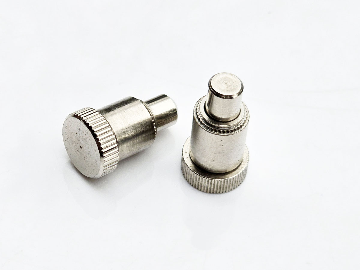
Broaching fastener specifications frequently refer to torque-out and push-out performance.
These are useful engineering parameters, but published values should never be separated from their test conditions.
Retention can vary with:
Laminate grade
Glass reinforcement
Resin system
Board thickness
Moisture condition
Hole tolerance
Fastener geometry
Material and heat treatment
Installation tooling
Installation conditions
Test method
For an OEM qualification project, the most useful question is therefore not:
What is the maximum torque-out value of this fastener?
It is:
What performance can this fastener achieve in our specified production substrate, hole condition, board thickness, and installation process?
That question leads naturally to sample testing rather than catalog-number comparison alone.
AI servers and high-density computing equipment place substantial mechanical demands on electronic assemblies.
A modern server platform may contain large multilayer motherboards, GPU or accelerator assemblies, high-current power distribution hardware,
heat sinks, daughterboards, network interfaces, and power conversion modules.
Broaching standoffs, nuts, and studs may be evaluated where a PCB or suitable non-metallic structural layer requires an integrated mechanical mounting feature.
Possible applications include:
Server motherboard mounting
Daughter-card spacing
Power supply control boards
Internal electronic modules
Mechanically supported board assemblies
In these systems, fastening decisions should also consider serviceability.
A threaded mounting point that survives initial assembly but degrades after repeated screw installation may create field-maintenance problems later.
Repeated assembly-cycle requirements should therefore be communicated during the RFQ stage where relevant.
Telecommunications equipment often combines dense electronics with vibration, thermal cycling, field maintenance, and restricted packaging space.
Potential applications for broaching hardware include:
5G radio equipment
Network switching hardware
Optical communications equipment
RF modules
Base-station electronics
Power conversion boards
Broaching standoffs can provide defined PCB spacing, while broaching nuts can establish reusable attachment points for serviceable modules.
For outdoor telecommunications equipment, fastener material and finish should also be evaluated against the enclosure environment rather than selected only from the PCB perspective.
Electric vehicles and electrified industrial systems use increasingly sophisticated electronic control and power-conversion assemblies.
Potential applications include:
Battery management system boards
Inverter control boards
Charging electronics
DC/DC converter assemblies
Power distribution electronics
Auxiliary control modules
These environments may involve vibration, temperature cycling, electrical isolation requirements, and relatively heavy electrical components.
A broaching fastener used near a busbar or power module should therefore be evaluated as part of the complete electromechanical assembly.
Mechanical retention, electrical clearance, insulation strategy, thermal expansion, and service loads may all matter.
Energy storage systems, UPS equipment, industrial inverters, and power conversion platforms often combine heavy electrical components with control electronics.
Broaching hardware may be considered for control PCB mounting, monitoring boards, communication modules, power supply boards, board-to-structure attachment, and mechanically supported electrical assemblies.
In these applications, procurement teams should communicate environmental requirements clearly.
Material and finish selection may depend on humidity, temperature, corrosion exposure, electrical considerations, and customer-specific requirements.
Semiconductor manufacturing equipment and automated industrial systems can contain large numbers of controllers, sensors, drives, power electronics, and precision electronic modules.
Fastening requirements may include precise component positioning, compact board spacing, repeated service access, vibration resistance, long equipment life, and stable threaded attachment points.
Broaching nuts and standoffs can be evaluated where the selected substrate and mechanical architecture support this fastening method.
The key is to treat the fastener as part of the equipment architecture rather than as generic purchased hardware.
Medical diagnostic and laboratory equipment frequently combines precision electronics with demanding mechanical packaging.
Potential applications include imaging electronics, detector boards, instrumentation, laboratory automation, control modules, and sensor assemblies.
Requirements vary significantly by equipment type.
Where a fastener becomes part of a regulated or safety-critical assembly, the applicable customer specification, validation requirements,
material documentation, traceability requirements, and quality plan must be defined by the project.
A generic broaching fastener specification should not be assumed to satisfy a particular medical-device requirement without qualification.
Broaching hardware may be produced from different metallic materials depending on product design and application requirements.
Possible material families include:
Carbon steel
Stainless steel
Brass
Other engineered materials where required by the application
Material selection should consider more than corrosion resistance.
Engineers and sourcing teams may need to evaluate mechanical strength, fastener geometry, thread performance, corrosion environment,
galvanic compatibility, electrical requirements, finish compatibility, temperature, assembly process, and customer specifications.
For example, stainless steel may be attractive for corrosion resistance, but this does not automatically make it the optimum choice for every PCB assembly.
Depending on fastener material and application, surface finishes may be specified for corrosion protection, appearance, electrical requirements, or compatibility with surrounding components.
Potential finish requirements should be defined on the customer drawing or purchasing specification.
The correct finish depends on factors such as:
Base material
Corrosion environment
Electrical contact requirements
Mating materials
Soldering-process proximity
Restricted-substance requirements
OEM specifications
Procurement teams should avoid replacing one finish with another solely because the appearance is similar.
A finish change can affect dimensions, friction, electrical behavior, corrosion performance, and installation characteristics.
Global electronics manufacturers may require either metric or Unified inch threads.
Project requirements may therefore include ISO metric threads, UNC or UNF threads, customer-specific thread tolerances, special thread lengths, custom standoff heights, or custom stud projections.
When qualifying an alternative supplier, the complete thread specification should be checked rather than relying on nominal diameter alone.
Thread pitch, tolerance class, engagement length, mating hardware, and functional assembly requirements all matter.
Standard hardware is often the most economical choice when an established configuration satisfies the mechanical design.
However, OEM electronics programs may require modified or custom geometry because of:
Unusual board thickness
Limited component clearance
Special standoff height
Restricted flange diameter
Custom thread length
Enclosure stack-up
Electrical clearance
Installation tooling
Legacy hardware replacement
In these cases, the customer drawing becomes the primary engineering definition.
A custom fastener project should begin with a dimensional and application review before tooling or mass production is committed.
Electronics manufacturers frequently need an alternative source for an existing broaching nut, stud, or standoff.
A functional equivalent should not be qualified by appearance or nominal thread size alone.
A proper comparison should include:
Overall geometry
Mounting-hole requirement
Shank diameter
Broaching feature geometry
Flange dimensions
Installed height
Thread specification
Material
Surface finish
Substrate thickness
Installation method
Required retention performance
Where the original component is defined by another manufacturer's proprietary part number, the safest qualification process is to compare the customer's drawing,
assembly requirements, and test criteria rather than assume dimensional equivalence from a cross-reference table.
For strategic sourcing and supplier-development teams, a structured qualification process reduces risk.
Begin with the existing 2D drawing, 3D model, customer specification, dimensional information, or physical sample where appropriate.
Next, define the actual substrate, including board material, board thickness, mounting-hole condition, finished hole dimension, and relevant mechanical constraints.
The alternative fastener can then be reviewed for mounting shank geometry, retention features, flange dimensions, thread, installed height, standoff length or stud projection, material, and finish.
Samples should be installed in representative substrate material whenever practical.
Depending on the application, validation may include dimensional inspection, installation assessment, visual board inspection,
torque-out testing, push-out testing, mating screw testing, repeated assembly cycles, environmental testing, or complete assembly testing.
Once the configuration has been validated, the agreed drawing and technical requirements should become part of the controlled production purchasing specification.
This approach is considerably more reliable than approving an alternative simply because it fits into the same nominal hole.
A complete RFQ reduces unnecessary clarification between engineering, purchasing, and the fastener manufacturer.
For broaching nuts, broaching studs, broaching standoffs, and custom PCB fasteners, provide as much of the following information as possible:
2D drawing
3D STEP model if available
Required fastener type
Thread specification
Substrate material
Board or substrate thickness
Mounting-hole diameter and tolerance
Plated or non-plated hole condition where relevant
Flange restrictions
Installed height
Stud projection or standoff length
Fastener material
Surface finish
Corrosion requirements
Electrical requirements where applicable
Required torque-out or push-out performance if specified
Sample quantity
Prototype schedule
Estimated annual usage
Packaging requirements
Quality or documentation requirements
This information allows the manufacturer to evaluate the complete fastening interface instead of quoting only from a thread designation.
Legacy equipment sometimes contains PCB hardware for which the original specification is no longer available.
In that situation, useful information can include clear photographs, a physical sample, nominal thread, overall dimensions,
flange diameter, installed height, mounting-hole diameter, board thickness, substrate description, application description, and required annual quantity.
A physical sample can support dimensional review, but the replacement should still be validated in the actual assembly before production release.
One common mistake is selecting by thread size alone. Two broaching nuts with the same thread may require different mounting holes or produce different retention behavior.
Another is treating FR4 like sheet metal. The installation mechanism must be compatible with the substrate.
PCB stack-up should not be ignored. Mechanical installation can interact with internal copper structures and laminate construction.
An approximate mounting-hole diameter should not be substituted for the specified interface dimension. Interference-based retention can be sensitive to hole condition and dimensional variation.
Published retention values should not automatically be applied to every board construction.
Installation tooling also matters. Correct hardware installed with poor alignment or inadequate board support can still damage the assembly.
Surface finishes should not be substituted without engineering review because finish changes may affect dimensions, corrosion behavior, electrical characteristics, and installation performance.
Finally, a second source should never be qualified from visual appearance alone. A visually similar fastener is not necessarily a functional equivalent.
A useful selection process starts with the host material.
If the host material is suitable ductile sheet metal, evaluate self-clinching nuts, studs, standoffs, floating fasteners, captive hardware, or other engineered panel fasteners according to the application.
If the host is a PCB, glass-epoxy laminate, or another suitable relatively non-ductile substrate requiring mechanically installed threaded hardware,
evaluate broaching nuts, broaching studs, or broaching standoffs designed for the specific substrate.
If the PCB manufacturing process favors soldered attachment, evaluate suitable surface-mount threaded hardware together with its land-pattern, soldering, and mechanical-load requirements.
If the project requires unusual board thickness, geometry, thread, material, finish, or mechanical performance, a custom fastener manufactured from the customer drawing may be the more appropriate solution.
This substrate-first decision path is generally more useful than beginning with a fastener catalog and attempting to make the assembly fit the hardware.
Broaching fasteners should form part of a broader engineered fastening architecture.
For OEMs designing electronic equipment, related product families may include Self-Clinching Fasteners for suitable metal panels,
Self-Clinching Nuts, Self-Clinching Studs, Self-Clinching Standoffs, Floating Self-Clinching Nuts, Captive Panel Screws, Snap-In Standoffs,
Keyhole Standoffs, Functional Equivalent Fasteners, and Custom Fasteners from Drawings.
This allows an OEM to select the fastening technology according to the material and function of each part of the enclosure instead of forcing one retention method across the entire assembly.
A productive broaching fastener supplier relationship begins with the assembly problem rather than only a request for unit price.
For a new program, the commercial path should normally move from application review and substrate definition to mounting-interface review,
drawing confirmation, samples, installation testing, mechanical validation, specification approval, and finally production quotation.
For an existing program requiring a second source, the process can begin with the existing drawing or physical sample,
followed by dimensional comparison, material and finish review, substrate compatibility assessment, sample production, board validation, supplier qualification, and volume sourcing.
This gives the engineer a component evaluated against the actual assembly while giving procurement a specification that can be quoted, compared, qualified, and controlled through production.
PCB hardware operates at the intersection of mechanical fastening and electronics manufacturing.
That makes apparently small specification changes important.
A change in board thickness, hole tolerance, laminate construction, fastener geometry, finish, or installation process may affect the mechanical interface.
For this reason, generic torque-out, push-out, installation-force, or keep-out values should not be treated as universal engineering limits.
Where these parameters are critical, they should be established from the selected fastener design, applicable technical specification, representative production substrate, and agreed validation method.
This is particularly important for high-value populated PCBs, multilayer server boards, EV electronics, power electronics, telecommunications infrastructure,
semiconductor equipment, medical electronics, and assemblies subject to repeated maintenance.
Validating the fastener/substrate interface before volume production can help prevent a small mechanical component from becoming a costly PCB assembly problem later in the program.
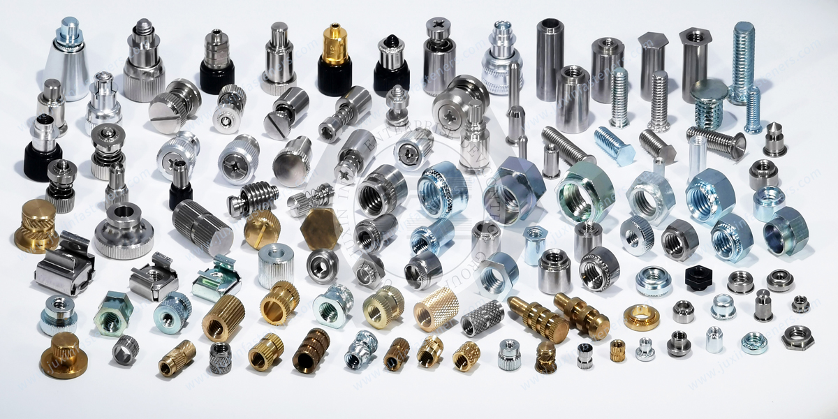
JUXIN FASTENERS manufactures and supplies engineered fastening components for industrial OEM applications, including broaching nuts, broaching studs,
broaching standoffs, PCB fastening hardware, self-clinching fasteners, studs, nuts, standoffs, and custom fasteners manufactured to customer drawings.
For electronics packaging and PCB projects, our engineering and sales teams can review the fastener interface together with the customer's substrate, mounting-hole requirements,
thread specification, material, finish, and assembly conditions.
For second-source projects, customers can provide an existing drawing or physical sample for dimensional and application review.
For new or custom projects, send your 2D drawing or available CAD data, PCB or substrate material, board thickness, mounting-hole specification,
required thread, nut/stud/standoff configuration, material and surface-finish requirements, mechanical performance requirements where applicable, prototype quantity, and estimated annual usage.
Where substrate-dependent retention is critical, sample validation in representative production material should be completed before volume approval.
Email: info@juxinfasteners.com
Website: www.juxinfasteners.com
Send your PCB hardware drawing or application requirements for a broaching fastener technical review, sample evaluation, second-source qualification, or volume RFQ.
Product Packaging
Packaging Standard
At Juxin Fasteners, we apply standardized export packaging to ensure product protection, traceability, and compliance with international logistics requirements.
1. Standard Export Packaging
Unless otherwise specified, all products will be packed according to our factory standard export packaging, which includes:
Moisture-resistant inner protection
Poly bag or small box packing as required
Reinforced export cartons
Clear labeling with part number, specification, batch number, and quantity
Palletizing for sea or air shipment when necessary
Our standard packaging is designed to ensure safe transportation, efficient warehousing, and long-distance international shipping.
2. Customized Packaging Options
We also provide customized packaging solutions according to customer requirements, including but not limited to:
Private labeling
Customized barcodes
Specific carton dimensions
Retail packaging
Special pallet configuration
Customer-specific marking and identification
So that you know, customized packaging may involve additional costs and extended lead time depending on the complexity of the requirements.
3. Compliance & Quality Assurance
All packaging processes are controlled under our ISO 9001 quality management system to ensure consistency, traceability, and product integrity throughout the supply chain.
Product Pictures
Contact Us
Tel.:
+86 020 8621 0320
+86 020 3121 6067
E-mail:
Technical Support:
Navigation
SEND INQUIREY