Call Us
+86 136 6007 9809
Call Us
+86 136 6007 9809

Heavy equipment, rail vehicles, commercial transportation systems, industrial machinery,
and outdoor power equipment place access-panel fasteners under conditions very different from those found in stationary indoor enclosures.
Product Specification
Heavy equipment, rail vehicles, commercial transportation systems, industrial machinery,
and outdoor power equipment place access-panel fasteners under conditions very different from those found in stationary indoor enclosures.
A service panel may experience:
continuous vibration
transverse joint movement
mechanical shock
structural flexing
engine or motor excitation
fan and pump vibration
repeated thermal cycling
gasket compression and relaxation
frequent maintenance opening and closing
Under these conditions, simply making a screw captive does not automatically prevent loosening.
This distinction is fundamental.
A captive fastener is designed primarily to remain retained to the panel when disengaged from its mating thread.
A vibration-resistant fastening system is designed to maintain the required joint condition under specified dynamic loads.
The same assembly may perform both functions, but they are not mechanically identical.
For demanding equipment, engineers may therefore combine captive panel hardware with carefully selected anti-loosening features such as prevailing-torque elements,
engineered thread interference, suitable spring mechanisms, controlled clamp load, appropriate drive systems, and assembly-level validation.
Also searched as vibration-resistant captive screws, heavy-duty captive panel screws, shock-resistant panel screws, captive screws for vibration,
self-locking captive fasteners, anti-loosening captive screws, and retained panel fasteners,
these components are used where service access, hardware retention, and dynamic joint reliability must be considered together.
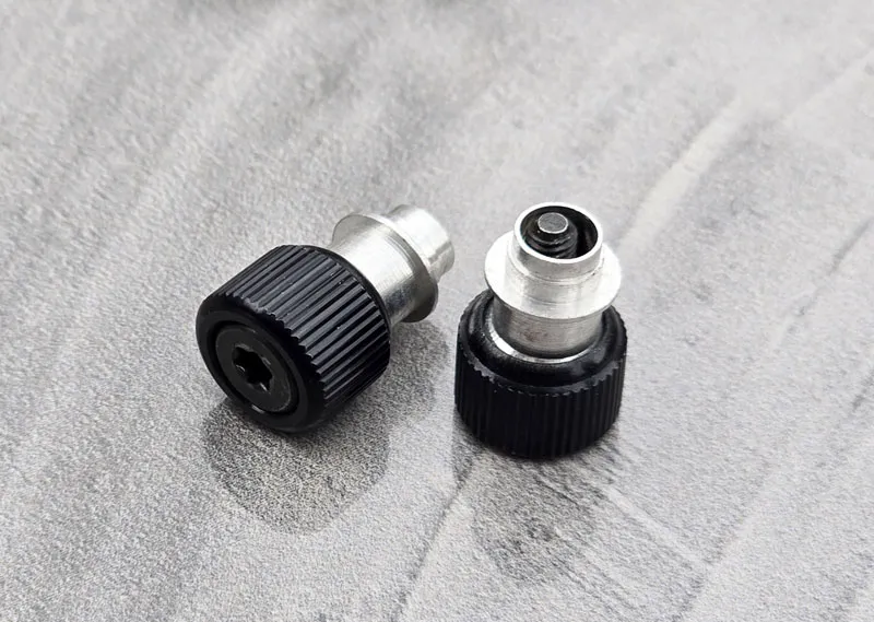
A vibration-resistant captive fastener is a retained panel-fastening assembly engineered for applications where vibration or shock could otherwise contribute to loss of clamp load,
rotational loosening, panel movement, or disengagement.
Depending on the design, the assembly may include:
a captive screw
retaining sleeve
ferrule or panel retainer
compression spring
prevailing-torque thread feature
polymer locking patch
deformed-thread locking feature
washer or load-distribution feature
tool-actuated drive
application-specific panel interface
Not every vibration-resistant captive fastener uses all of these elements.
The correct architecture depends on the actual joint.
This is one of the most important concepts when specifying captive panel hardware.
Captive retention answers:
“What happens to the screw after it is disengaged?”
The screw remains attached to the access panel or assembly rather than becoming a loose component.
Anti-loosening answers:
“What happens while the screw is tightened and the equipment is operating?”
The joint must maintain sufficient mechanical integrity under the specified service conditions.
A screw can therefore be:
captive but not specifically vibration resistant
vibration resistant but not captive
both captive and vibration resistant
OEM engineers should specify both requirements independently.
A properly tightened screw creates clamp load between joined components.
That clamp load generates friction within the joint and helps prevent relative movement.
Under dynamic service conditions, several mechanisms can reduce joint stability.
These can include:
transverse movement between joint members
embedment or settling
gasket relaxation
thermal expansion and contraction
panel flexing
insufficient initial preload
thread or bearing-surface slip
repeated shock loading
Severe transverse movement is particularly important because relative slip at the thread and bearing interfaces can contribute to rotational self-loosening.
The actual mechanism depends on the complete joint rather than vibration frequency alone.
When an access-panel screw repeatedly loosens, changing the screw is not always the first or only engineering solution.
The root cause may be:
inadequate clamp load
excessive joint movement
flexible panel construction
insufficient fastener quantity
excessive spacing between fasteners
gasket relaxation
poor bearing surface
incorrect tightening process
thermal cycling
unsuitable locking technology
This means anti-loosening design should begin with the joint architecture.
The useful engineering sequence is:
Dynamic environment → joint movement → preload behavior → panel stiffness → locking requirement → fastener selection
rather than:
Vibration exists → add a locking patch
The purpose of tightening a panel screw is not merely to prevent the screw from rotating.
It is to establish the required joint condition.
For many access panels, clamp load may need to:
hold the panel against the frame
prevent rattling
maintain electrical bonding where required
compress an environmental gasket
prevent local movement
support structural alignment
If clamp load decreases, relative movement can increase.
That movement can further increase the risk of loosening.
This interaction is why tightening torque, panel stiffness, gasket behavior, fastener spacing, and anti-loosening technology should be evaluated together.
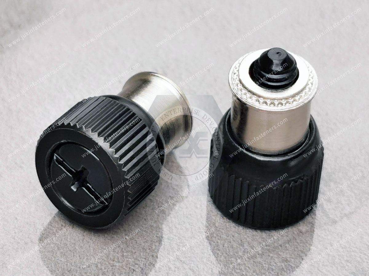
Both conventional screws and captive screws can be engineered for vibration-resistant joints.
The captive configuration adds hardware-retention benefits.
| Design Consideration | Conventional Loose Screw | Captive Panel Fastener |
|---|---|---|
| Hardware retained after disengagement | No | Yes, when correctly designed |
| Loose-part risk during service | Higher | Reduced |
| Maintenance handling | Screw must be separately controlled | Screw remains associated with panel |
| Anti-loosening capability | Depends on joint and locking system | Also depends on joint and locking system |
| Spring-loaded option | Application dependent | Common in some captive assemblies |
| Tool-controlled tightening | Available | Available |
| Suitability for vibration | Depends on complete joint | Depends on complete joint |
Captivity should therefore not be used as a synonym for vibration resistance.
Prevailing-torque systems create resistance to screw rotation beyond the torque produced solely by joint clamp load.
Depending on the design, this may be achieved through:
polymeric interference elements
controlled thread deformation
specialized mating-thread geometry
other engineered interference mechanisms
The prevailing torque must be compatible with:
installation torque
removal torque
service cycles
mating-thread material
temperature
coating
lubrication
required clamp load
Too little prevailing torque may provide insufficient rotational resistance.
Too much can interfere with assembly, increase tool load, or make it difficult to distinguish locking torque from clamp-generating torque.
A polymeric locking patch can be applied to a selected portion of the male thread.
As the screw enters the mating thread, the patch creates interference and increases rotational resistance.
Potential advantages can include:
pre-applied locking feature
no separate loose locking component
compatibility with production assembly
potential reuse depending on the specific locking system and qualification requirements
However, polymer locking performance depends on the actual material and product specification.
Important variables include:
polymer type
application thickness
thread size
mating thread
installation torque
operating temperature
chemical exposure
number of service cycles
storage conditions
There is no universal temperature rating or reusable-cycle count that applies to every polymer patch.
Supplier data and application validation should control the specification.
These technologies are sometimes grouped together, but they operate differently.
A polymeric prevailing-torque patch primarily creates mechanical interference during thread engagement.
A microencapsulated thread-locking adhesive contains chemical components that are activated during assembly and form an adhesive locking mechanism.
Their:
installation behavior
curing behavior
reuse capability
temperature capability
removal characteristics
can differ significantly.
An OEM drawing should identify the intended locking technology rather than using ambiguous terms such as “locking patch” when a specific mechanism is required.
Some all-metal locking systems use controlled thread deformation or other interference geometry.
These can provide prevailing torque without relying on a polymer locking element.
Potential reasons to evaluate an all-metal solution include:
temperature requirements
chemical exposure
material compatibility
service requirements
customer specifications
However, all-metal prevailing-torque designs can affect installation and removal torque and should be matched to the mating thread.
The complete system should be qualified rather than assuming that more interference always provides better vibration resistance.
Specialized thread forms or mating systems may also be used to improve resistance to self-loosening.
These should not be treated as interchangeable with standard ISO metric or Unified thread systems unless the design specifically provides for that compatibility.
Where a proprietary or specialized thread geometry is required, procurement should define:
male thread geometry
mating female thread
installation requirement
material
coating
inspection method
licensing or sourcing constraints where applicable
For second-source projects, thread geometry must be verified rather than inferred from nominal diameter and pitch.
Spring-loaded captive screws are useful in many service-panel applications.
A compression spring can:
retract or extend the screw depending on architecture
keep the screw positioned during panel removal
assist alignment
prevent the screw from falling loosely within the retainer
improve service handling
provide controlled axial positioning
However, the spring should not automatically be assumed to maintain the full structural clamp load of the joint.
Once a threaded captive screw is tightened, joint clamp load is primarily governed by the tightened threaded connection and the complete joint architecture.
The spring's role depends on the specific fastener design.
This distinction prevents a common specification error.
A captive screw's internal spring may apply a relatively small axial positioning force.
The tightened screw may generate a much larger joint preload.
These are different forces with different functions.
Therefore:
Spring force ≠ tightening preload
and:
Spring force ≠ guaranteed anti-loosening performance
The spring should be specified for its intended captive or positioning function.
The threaded joint should be engineered separately for clamp load and dynamic stability.
A standard captive screw may be entirely suitable for equipment with modest dynamic loading.
Additional locking features may be considered when the service environment or consequences of loosening justify them.
| Engineering Factor | Standard Captive Hardware | Vibration-Engineered Captive Hardware |
|---|---|---|
| Captive screw retention | Yes | Yes |
| Dedicated prevailing-torque feature | Optional | May be specified |
| Spring mechanism | Design dependent | Design dependent |
| Tool-actuated drive | Available | Often useful |
| Dynamic qualification | Application dependent | Often important |
| Reusability | Product dependent | Must consider locking technology |
| Environmental capability | Material/finish dependent | Material/finish dependent |
| Appropriate applications | Depends on joint | Depends on dynamic requirement |
The selection should be based on risk and actual service conditions rather than equipment category alone.
A strong fastener cannot compensate indefinitely for an excessively flexible access panel.
Panel deflection can reduce local clamp load and allow relative movement.
Factors affecting panel stiffness include:
sheet thickness
material
panel span
bends
beads
ribs
flanges
fastener spacing
cutouts
gasket stiffness
If the center of a large service panel moves significantly between fastener locations, increasing locking torque at each screw may not solve the underlying joint problem.
Fastener spacing influences:
panel deflection
gasket compression
vibration
local clamp distribution
sealing performance
rattling
There is no universal spacing that works for all access panels.
The correct pattern depends on:
panel dimensions
sheet stiffness
frame stiffness
gasket compression characteristics
external loads
fastener clamp load
environmental requirements
Large outdoor panels may require more attention to spacing and structural stiffness than small rigid covers.
Captive screws are frequently used on access panels that compress elastomeric gaskets.
In these assemblies, fastener design interacts with sealing design.
Important variables include:
gasket material
gasket thickness
compression range
compression set
panel stiffness
frame flatness
fastener spacing
tightening sequence
service temperature
aging
A vibration-resistant screw does not automatically create a weatherproof enclosure.
It only contributes to maintaining the mechanical joint.
Environmental sealing must be validated at the enclosure level.
This is especially important for BESS containers, rail equipment, outdoor cabinets, wind-energy equipment, and heavy machinery.
A panel may include high-quality captive screws and still fail environmental ingress requirements because of:
gasket discontinuities
panel distortion
inadequate compression
weld seams
cable entries
ventilation openings
door hinges
coating damage
Therefore, terms such as waterproof, weatherproof, IP-rated, or sealed should only be used when the complete enclosure has been designed and validated accordingly.
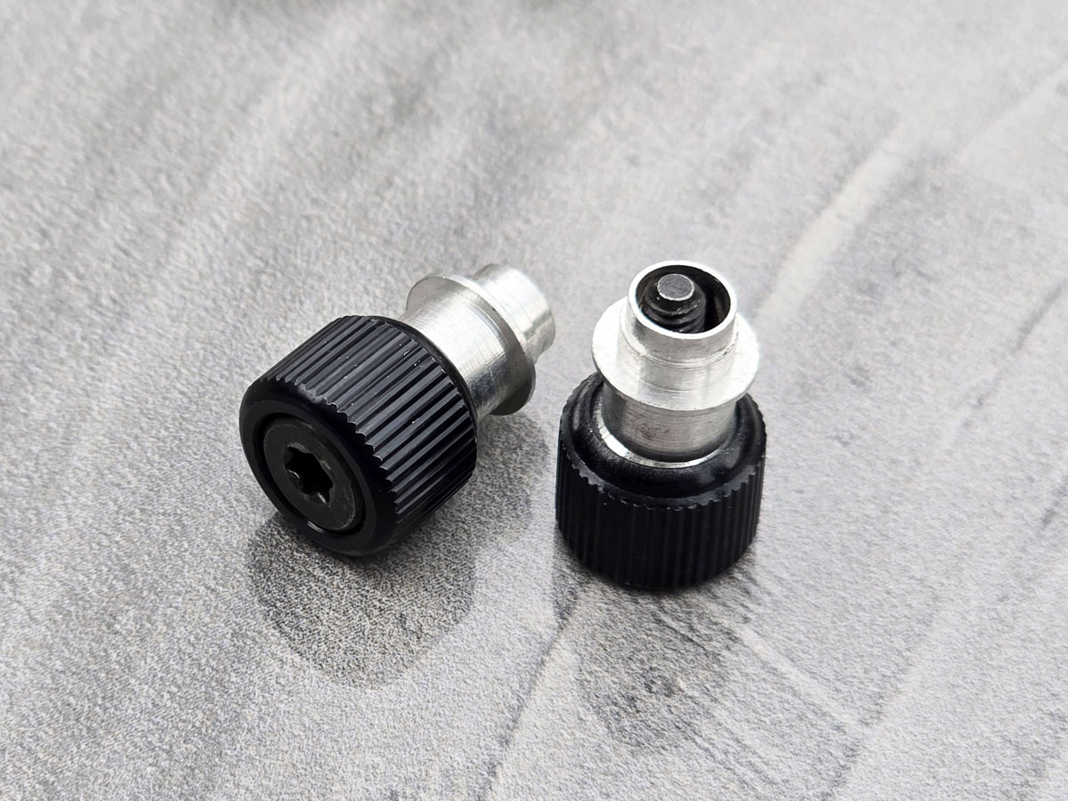
Tool-actuated heads can be useful where maintenance procedures require controlled tightening.
Common drive options may include:
internal hex
Torx-style drives
slotted drives
cross recesses
external hex
tamper-resistant drives where required
The appropriate drive depends on:
required torque
tool access
service frequency
field environment
operator requirements
tamper-control requirements
available installation tools
A tool-actuated design can make controlled tightening easier, but the presence of a Torx or hex drive does not itself guarantee correct preload.
Where joint integrity is important, tightening procedures should be established for the actual fastener and assembly.
Torque behavior can be influenced by:
thread friction
head-bearing friction
plating
lubrication
polymer locking patches
deformed threads
gasket compression
mating-thread material
A locking element adds torque that may not directly contribute to clamp load.
This distinction matters when specifying installation torque.
With a prevailing-torque fastener, the tool may need to overcome:
Prevailing torque + torque required to generate clamp load
This means the total measured installation torque is not necessarily equivalent to the clamp-generating torque of a free-running screw.
For critical joints, engineers should consider how the locking element affects the torque-tension relationship.
This is particularly important when changing locking technologies during second-source qualification.
Heavy-equipment access panels may be opened repeatedly during maintenance.
The drive interface should therefore be evaluated for:
installation torque
removal torque
repeated tool engagement
contamination
field accessibility
corrosion
operator tool availability
A drive system that works well in a clean production environment may behave differently after years of outdoor service.
The captive screw is only one part of the assembly.
The panel-retention component may use:
self-clinching installation
flaring
swaging
riveting
other mechanical retention methods
Its compatibility depends on:
panel material
panel thickness
mounting-hole diameter
sheet hardness
installation tooling
required retention load
Second-source qualification should therefore include the retainer body as well as the screw.
Under severe service loads, failure may occur at the panel-retention interface rather than at the thread.
Potential failure modes can include:
retainer pull-out
panel deformation
sleeve rotation
local sheet cracking
hole enlargement
The correct validation program should identify the actual load path and likely failure mode.
Potential captive-fastener materials can include:
carbon steel
stainless steel
other engineered materials where technically appropriate
Material selection should consider:
mechanical strength
host-panel compatibility
corrosion
temperature
wear
service cycles
electrical requirements
customer specifications
The material should be selected as part of the complete assembly.
Possible surface treatments can include:
zinc-based coatings
zinc-nickel coatings
zinc flake systems
passivated stainless steel
customer-specified finishes
Corrosion performance depends on the exact coating system, thickness, substrate, pretreatment, geometry, test method, and acceptance criteria.
A generic finish name should not automatically be assigned a universal salt-spray duration.
If a customer requires corrosion testing, the RFQ should define the applicable standard and acceptance requirement.
Relevant test methods may include ASTM or ISO corrosion-test procedures where specified by the customer.
Salt-spray testing is useful for comparative coating evaluation and specification compliance.
However, a specified number of salt-spray hours should not be interpreted directly as an equivalent number of years in outdoor service.
Actual field corrosion depends on:
chloride exposure
humidity
temperature
wet/dry cycles
galvanic couples
coating damage
chemical exposure
installation environment
Procurement should therefore use corrosion test requirements as controlled qualification criteria rather than simple field-life predictions.
Rail vehicles expose equipment to continuous vibration, track inputs, braking loads, thermal cycling, and repeated service access.
Potential captive-fastener applications include:
propulsion control cabinets
traction inverter enclosures
passenger-car electrical cabinets
HVAC control boxes
battery enclosures
underfloor equipment covers
communication equipment panels
Vibration-resistant captive hardware can be evaluated where retained service screws and controlled joint stability are required.
Rail applications should follow the OEM's applicable mechanical, environmental, fire, electrical, and validation requirements.
Heavy trucks, buses, utility vehicles, and specialty commercial vehicles may use captive panel hardware on:
battery box covers
electrical compartments
engine access panels
control enclosures
auxiliary power equipment
service doors
The appropriate locking technology depends on actual vehicle vibration, panel stiffness, service interval, corrosion environment, and maintenance requirements.
Excavators, loaders, graders, cranes, and other off-highway equipment operate under severe mechanical conditions.
Potential applications include:
engine compartment panels
hydraulic-system access doors
electrical cabinets
operator-cab service panels
cooling-system covers
control boxes
Captive hardware can reduce the risk of service screws being dropped or lost during maintenance in field conditions.
Where vibration resistance is required, the joint should be validated against representative equipment loads.
Mining machinery can combine:
shock
vibration
dust
moisture
abrasive contamination
large temperature changes
difficult field maintenance
Potential applications include:
crusher control panels
haul-truck equipment covers
conveyor control enclosures
electrical cabinets
hydraulic service doors
Material, coating, drive geometry, and locking method should be selected according to the actual environment.
Containerized Battery Energy Storage Systems combine large outdoor enclosures with power electronics, battery modules,
HVAC or thermal-management equipment, monitoring electronics, and high-voltage systems.
Potential captive-fastener applications include:
electrical service panels
inverter covers
auxiliary control cabinets
battery-management enclosures
HVAC access covers
equipment compartments
Cooling fans, outdoor exposure, transportation, thermal cycling, and service access can all influence fastening requirements.
For gasketed exterior panels, fastener selection should be coordinated with the enclosure sealing strategy.
Wind turbines contain control cabinets, power electronics, converters, pitch systems, and serviceable equipment inside towers and nacelles.
Potential applications include:
converter cabinets
control-panel covers
nacelle service enclosures
auxiliary electrical equipment
sensor cabinets
Vibration, corrosion, maintenance accessibility, and long service intervals should be considered together.
Central inverters, grid-support equipment, transformer controls, and outdoor power cabinets may use retained panel hardware for frequent or controlled service access.
The fastening system may need to account for:
outdoor corrosion
thermal cycling
fan vibration
gasket compression
electrical safety
maintenance procedures
Captive retention helps control loose hardware, while vibration resistance must be engineered through the complete joint.
Automotive and EV equipment can use captive fasteners in:
electrical enclosures
power electronics
battery-related service covers
charging electronics
auxiliary control modules
commercial EV equipment
Automotive applications may impose customer-specific requirements for vibration, thermal cycling, corrosion, traceability, and production validation.
The correct fastener architecture should be qualified for the actual program.
Industrial machines contain access panels for:
motors
drives
control systems
hydraulic equipment
electrical components
lubrication systems
safety systems
Repeated maintenance makes captive screws attractive because they remain associated with the panel.
Where machinery generates substantial vibration, additional anti-loosening features may be evaluated.
Many data-center systems are comparatively stationary, but captive panel fasteners can still be useful for serviceability and loose-hardware control.
Applications can include:
rack power equipment
cooling systems
UPS equipment
power distribution equipment
serviceable server chassis
liquid-cooling infrastructure
Whether dedicated vibration-resistant features are necessary depends on the actual equipment environment, transportation loads, fans, pumps, service requirements, and joint design.
Telecommunications equipment may operate outdoors, on towers, beside transportation infrastructure, or in equipment shelters.
Potential applications include:
outdoor telecom cabinets
radio equipment
power systems
network enclosures
cooling equipment
service panels
Wind, fan vibration, transportation, corrosion, and repeated field maintenance can influence captive-fastener selection.
For demanding applications, fastener performance should be validated in a representative assembly.
A meaningful test program may consider:
vibration direction
frequency range
acceleration
displacement
duration
mechanical shock
panel geometry
fastener spacing
gasket
installation torque
temperature
service cycles
Applicable vibration or shock standards depend on the equipment industry and customer requirements.
The fastener supplier should not assume one generic test profile represents every application.
A screw tested alone cannot reproduce:
panel flexing
gasket relaxation
frame stiffness
joint slip
fastener spacing
equipment resonance
thermal effects
For critical programs, the actual or representative panel assembly provides more meaningful information.
Testing may evaluate:
residual tightening condition
rotational movement
clamp-load change
panel rattling
fastener disengagement
retainer damage
gasket condition
Acceptance criteria should be defined before testing.
A supplier should not state that a fastener can never loosen under vibration without defining the test conditions.
A more technically useful requirement is:
No unacceptable rotational loosening or loss of joint function under the specified vibration and shock test profile.
This connects the requirement to:
actual equipment loads
installation torque
test duration
panel construction
acceptance criteria
It also creates a qualification requirement that can be compared between suppliers.
Serviceable captive hardware may be opened and closed repeatedly.
Reusability can be affected by:
locking technology
polymer wear
thread deformation
coating wear
corrosion
drive wear
mating-thread condition
installation torque
There is no universal number of reuse cycles for all vibration-resistant captive fasteners.
If repeated service is important, the OEM should specify a required maintenance-cycle qualification.
A locking system may perform well during initial assembly but change after repeated removal and reinstallation.
For serviceable equipment, engineers should ask:
What happens to prevailing torque after repeated cycles?
Does the locking element wear?
Does the mating thread change?
Does coating wear alter friction?
Does the required installation torque change?
Does the drive remain serviceable?
This makes lifecycle testing particularly important for rail, heavy machinery, BESS, and industrial equipment.
Procurement teams qualifying a second source should not compare vibration-resistant captive fasteners by thread size alone.
A functional-equivalent audit should include:
thread size
thread pitch
thread tolerance or class
screw length
grip or panel range
retainer geometry
mounting-hole requirement
locking technology
prevailing-torque characteristics
spring architecture where applicable
spring force or rate where functionally relevant
drive type
head geometry
fastener material
retainer material
surface finish
corrosion requirement
installation method
service-cycle requirement
dynamic validation requirement
Two assemblies can look nearly identical while behaving differently under vibration.
Begin with the customer's:
2D drawing
3D model
existing part number
physical sample
assembly specification
Provide known requirements for:
vibration
shock
equipment type
operating temperature
service interval
transportation
corrosion exposure
Provide:
panel material
panel thickness
mounting-hole dimensions
frame material
mating thread
gasket information
fastener spacing
tightening requirement
Determine whether the current assembly uses:
free-running thread
polymer prevailing-torque patch
adhesive locking feature
all-metal prevailing torque
specialized thread geometry
spring-assisted captive architecture
another locking method
Compare all functionally important dimensions and material requirements.
Confirm:
retainer installation
screw alignment
panel fit
drive access
thread engagement
gasket compression where applicable
Where prevailing torque is specified, evaluate it using the applicable customer-defined procedure.
For reusable assemblies, multiple installation and removal cycles may be required.
Evaluate the complete assembly under the specified vibration and shock profile.
Production approval should follow successful dimensional, material, assembly, environmental, and dynamic verification as required by the program.
When replacing one locking system with another, procurement should not assume that equal installation torque means equal joint performance.
A replacement fastener may have different:
prevailing torque
friction coefficient
clamp-load relationship
removal torque
reuse behavior
The qualification process should therefore distinguish between:
free-running torque
prevailing torque
final tightening torque
removal torque
This is especially important for calibrated assembly processes.
Where the existing part includes a defined coating requirement, the second source should match the actual specification rather than only the coating name.
Important factors can include:
substrate
coating type
coating thickness
topcoat
friction characteristics
corrosion test
acceptance criteria
appearance
environmental restrictions
If an OEM requires a particular ASTM, ISO, EN, or other internationally recognized test method, that requirement should be included on the drawing or purchase specification.
A technically complete RFQ allows the supplier to evaluate both the fastener and the joint.
For vibration-resistant captive fasteners, heavy-duty captive panel screws, shock-resistant panel screws, or custom retained access hardware, provide as much of the following information as possible:
2D drawing
3D STEP model where available
existing part number or physical sample
panel material
panel thickness
panel hardness where relevant
mounting-hole diameter
retainer installation method
mating-thread specification
thread size
thread pitch or threads per inch
thread tolerance or class
screw length
grip range
required drive profile
locking technology
prevailing-torque requirement where specified
spring requirement where applicable
fastener material
retainer material
surface finish
corrosion requirement
operating temperature range
chemical exposure
vibration requirement
shock requirement
tightening torque or assembly procedure
gasket details where applicable
environmental sealing requirement
expected service cycles
sample quantity
prototype quantity
Estimated Annual Usage (EAU)
packaging requirements
inspection requirements
documentation requirements
production schedule
If vibration data are not yet available, equipment type and known operating conditions can still help begin the technical discussion.
Useful supplier-qualification questions include:
Which captive retention method is proposed?
Which anti-loosening mechanism is proposed?
Are captivity and vibration resistance separate functions in this design?
What panel thickness and mounting-hole requirements apply?
What mating thread is required?
Is a prevailing-torque element used?
Is the locking technology reusable?
What service-cycle data are available for the specified configuration?
How does operating temperature affect the locking element?
What materials and finishes are available?
What installation tooling is required?
Can the supplier review our current 2D drawing?
Can samples be provided for assembly testing?
Can the supplier evaluate a physical sample for functional equivalence?
Can custom geometry be manufactured from our drawing?
What inspection and material documentation can be supplied?
What EAU is required for production pricing?
These questions help procurement distinguish a technically qualified solution from a visually similar replacement.
Standard captive hardware can satisfy many applications.
Custom development may be appropriate where the OEM requires:
non-standard thread
special screw length
unusual grip range
custom retainer geometry
special drive
unique spring configuration
defined prevailing-torque behavior
special material
special surface finish
restricted installation envelope
customer-specific panel geometry
application-specific service requirements
For OEM projects, custom development should be evaluated against volume, tooling, qualification cost, and the possibility of using an existing standard architecture.
Different teams may identify the same fastening problem differently.
A mechanical engineer may report panel movement.
A reliability engineer may find screw rotation after vibration testing.
A service technician may report lost screws during maintenance.
An enclosure engineer may see uneven gasket compression.
A procurement manager may need a second source for an existing captive assembly.
A supplier-development team may need to qualify a functional equivalent.
These problems can be translated into a common engineering and commercial workflow:
Service environment → joint failure mode → panel/gasket analysis → captive requirement → anti-loosening requirement
→ fastener architecture → drawing review → sample installation → dynamic validation → supplier qualification → production sourcing
This approach is more reliable than simply searching for a “vibration-proof screw.”
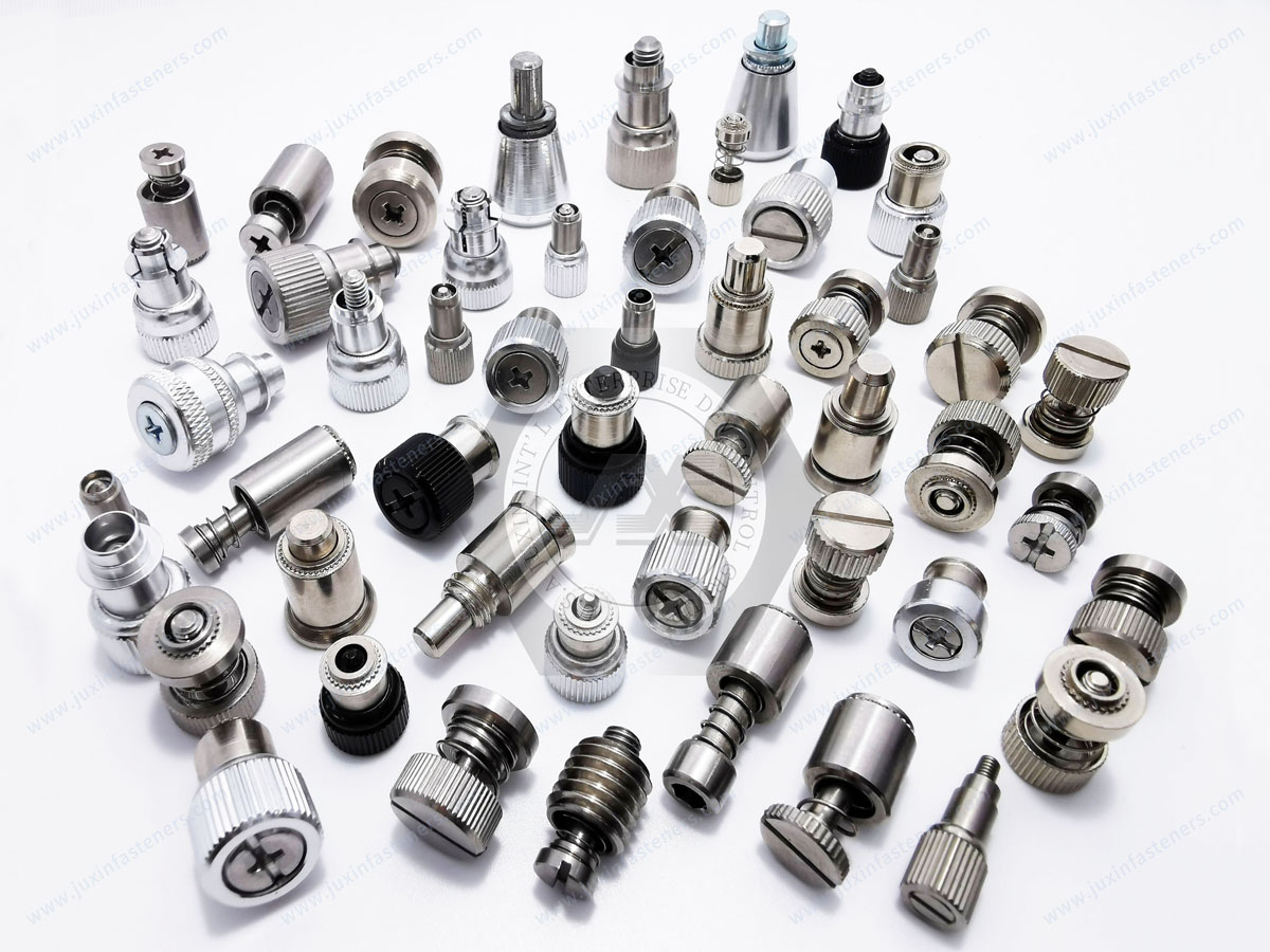
JUXIN FASTENERS supplies engineered captive panel hardware, vibration-resistant captive screws, spring-loaded captive fasteners,
tool-actuated panel screws, retained panel assemblies, and custom fastening components for OEM and industrial applications.
For projects involving vibration-resistant captive fasteners, heavy-duty captive panel screws, shock-resistant panel hardware,
spring-loaded captive screws, or custom equipment access fasteners, our team can review customer drawings and application requirements to evaluate the appropriate manufacturing and sourcing path.
Technical review can begin from:
a customer 2D drawing
a 3D model
an existing fastener specification
a physical sample
panel and mating-frame information
vibration and shock requirements
a functional-equivalent requirement
a new OEM access-panel application
Where dynamic joint performance is important, representative sample installation and assembly-level vibration or shock validation are recommended before final production approval.
Where environmental sealing is required, the captive fastener should be evaluated as part of the complete panel, gasket, frame, and enclosure system.
For drawing review, sample evaluation, functional-equivalent sourcing, custom vibration-resistant captive fastener development,
or production-volume quotation, send your technical requirements to JUXIN FASTENERS.
Email: info@juxinfasteners.com
Website: www.juxinfasteners.com
Product Packaging
Packaging Standard
At Juxin Fasteners, we apply standardized export packaging to ensure product protection, traceability, and compliance with international logistics requirements.
1. Standard Export Packaging
Unless otherwise specified, all products will be packed according to our factory standard export packaging, which includes:
Moisture-resistant inner protection
Poly bag or small box packing as required
Reinforced export cartons
Clear labeling with part number, specification, batch number, and quantity
Palletizing for sea or air shipment when necessary
Our standard packaging is designed to ensure safe transportation, efficient warehousing, and long-distance international shipping.
2. Customized Packaging Options
We also provide customized packaging solutions according to customer requirements, including but not limited to:
Private labeling
Customized barcodes
Specific carton dimensions
Retail packaging
Special pallet configuration
Customer-specific marking and identification
So that you know, customized packaging may involve additional costs and extended lead time depending on the complexity of the requirements.
3. Compliance & Quality Assurance
All packaging processes are controlled under our ISO 9001 quality management system to ensure consistency, traceability, and product integrity throughout the supply chain.
Product Pictures
Contact Us
Tel.:
+86 020 8621 0320
+86 020 3121 6067
E-mail:
Technical Support:
Navigation
SEND INQUIREY