Call Us
+86 136 6007 9809
Call Us
+86 136 6007 9809

Nov. 20, 2026
In precision medical analyzers, robotic actuators, power-electronics inverters, industrial sensors, and automated machinery, standard off-the-shelf fasteners may not satisfy specialized functional requirements. A standard bolt cannot simultaneously clamp a linkage and act as a tight-tolerance pivot axle without excessive play; an unreinforced plastic housing creeps and cracks under bolt preload without a precision metallic compression limiter; and standard catalog standoffs rarely match custom multi-board spacing, cross-drilled fluid/wire passages, or tight coaxial alignment across stacked housings.
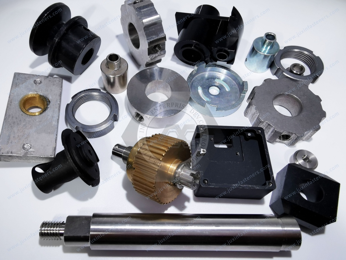
When off-the-shelf hardware forces engineers to add extra shims, rework standard parts, or tolerate assembly binding, moving to a made-to-drawing component resolves the mechanical failure mode directly. As an industrial fastener manufacturer, Juxin Fasteners manufactures custom CNC machined fasteners and precision components from customer 2D drawings and 3D CAD models—evaluating CNC turning, CNC milling, cold heading, cold forming, and applicable secondary operations for each part rather than forcing every drawing into one rigid manufacturing route.
Four Core Families of Custom Machined Fasteners and Precision Components
Precision Bushings, Sleeves, and Compression Limiters
Unthreaded and internally threaded cylindrical sleeves act as wear liners, alignment bushings, bearing journals, and compression limiters inside molded polymer or composite housings. Functional performance depends on inner-to-outer diameter coaxial alignment, wall-thickness uniformity, perpendicular end faces, and controlled surface finish so mating shafts rotate smoothly or clamping loads transfer cleanly without crushing surrounding plastics.
Custom Threaded Standoffs and Precision Spacers
Hex, round, knurled, or stepped standoffs control exact mechanical clearances between printed circuit boards, heatsinks, optical decks, and structural chassis plates. Made-to-drawing standoffs integrate custom lengths, blind thread depths, male-to-female steps, wrench flats, or press-fit features where catalog hardware cannot maintain assembly stack tolerances.
Stepped Shoulder Screws and Precision Shafts
Custom shoulder screws combine structural clamping with precision pivoting or linear guidance. Drawing-based manufacturing allows engineers to specify exact shoulder fit tolerances (such as ISO h6 or h8 where functionally required), controlled under-head fillet radii, dedicated retaining-ring or lubrication grooves, and specific metric or unified thread pitches unavailable in standard stripper-bolt catalogs.
Specialty Connecting Hardware, Pins, and Adapters
This category includes custom captive panel screw assemblies, knurled thumb screws, cross-drilled clevis pins, fluidic and sensor threaded adapters, eccentric adjustment pins, and specialty security or low-clearance drive fasteners designed for compact OEM maintenance envelopes.
Evaluating Manufacturing Routes: Pure CNC vs. Cold Forming Plus CNC Secondary Operations
Choosing the most economical production route is a major lever for OEM purchasing managers and design engineers. Because optimal manufacturability depends on head-to-shank diameter ratio, material machinability, critical tolerances, and annual volume, no manufacturing route is assigned to any specific part prior to engineering drawing review.
| Decision Factor | CNC Turning & Milling (From Bar Stock) | Cold Heading / Cold Forming + CNC Secondary Operations |
|---|---|---|
| Typical Volume Fit | Prototypes, pilot runs, low-to-medium industrial batch quantities | Medium-to-high industrial batch runs and recurring multi-year OEM programs |
| Dedicated Tooling & Changeover | Minimal custom tooling; fast design-revision turnaround via CNC programming | Requires forming dies and setup; tooling amortized across higher batch volume |
| Geometric Capability | Excels at deep undercuts, cross-holes, milled flats, thin walls, asymmetric features, and sharp stepped profiles | Well-suited to axisymmetric flanged, hex, or stepped blanks finished via CNC for tight shoulders, grooves, or cross-holes |
| Material Efficiency & Grain Flow | Higher chip removal when large flanges or heads are turned from wide bar stock | High material utilization; favorable formed grain flow can be beneficial for fatigue performance when geometry, material, heat treatment, and testing support the comparison |
| Dimensional Precision | Achieves tight datums, runout, and complex GD&T features directly on multi-axis lathes/mills | Combines near-net forming cost efficiency with CNC accuracy on critical functional datums |
| Thread Manufacturing | Single-point CNC threading or tapping (highly flexible for non-standard pitches) | High-speed thread rolling (smooth work-hardened flanks) or CNC threading where geometry dictates |
During drawing review, evaluating whether a high-volume bar-machined fastener can transition to a cold-formed near-net blank with CNC secondary finishing—or keeping complex low-volume hardware on pure CNC turning—often unlocks substantial cost reduction while maintaining identical functional tolerances.
GD&T, Surface Roughness, and Material Selection Trade-Offs
Dimensional Tolerances and Functional Datums
Applying standard general machining tolerances (such as ISO 2768-m) to non-critical surfaces keeps cycle time and inspection cost practical. Tighter bilateral tolerances (for example, illustrative precision zones around ±0.01 mm to ±0.025 mm) should be reserved strictly for functional fits such as bearing journals, press-fit sleeves, and seal grooves. Note that achievable tolerances on any specific drawing depend on diameter, length-to-diameter ratio, alloy, and post-machining processes and are confirmed during feasibility review rather than guaranteed universally.
Concentricity vs. Coaxiality and Runout (ASME Y14.5-2018 vs. ISO 1101)
On stepped shoulder screws, sleeves, and sensor adapters, alignment between thread axes, bearing shoulders, and locating diameters prevents assembly binding and eccentric wear. Engineers should align GD&T callouts with modern inspection standards:
Under ASME Y14.5-2018, the legacy concentricity symbol was removed because derived median points are difficult and expensive to measure reliably; engineers instead specify circular runout, total runout, or position relative to a functional datum axis.
Under ISO 1101, coaxiality/concentricity remains defined, though runout is still widely favored on cylindrical turned parts because it controls both coaxial alignment and form error in a way that inspects cleanly on the shop floor.
Completing coaxial features in a single CNC clamping setup—or using controlled secondary fixturing and precision grinding when warranted by the drawing—helps maintain tight runout across production batches.
Surface Roughness (Ra)
General structural spacers and static fasteners typically perform well with standard turned finishes (illustrative range around Ra 1.6–3.2 µm). Sliding bushings, dynamic bearing shoulders, and O-ring sealing grooves often specify smoother finishes (such as Ra 0.8 µm or finer), requiring tuned cutting geometry, controlled feed rates, or secondary grinding depending on the alloy and drawing specification.
Material Selection and Machinability
Free-Machining vs. Structural Alloy Steels: Free-machining carbon steels (such as 12L14 or 11SMn30 where regulatory lead/sulfur restrictions allow) offer rapid cycle times for non-structural spacers, whereas medium-carbon and alloy steels (such as 4140 / 42CrMo4) provide high strength and wear resistance after heat treatment for loaded shafts and custom bolts.
Stainless Steels (303, 304, 316/316L, 17-4PH): 303 stainless machines cleanly for indoor precision components; 304 and 316/316L provide higher corrosion resistance but work-harden rapidly, demanding rigid tooling and controlled cutting speeds; precipitation-hardening 17-4PH balances high mechanical strength with corrosion resistance when specified on high-load OEM drawings.
Brass (C36000 and Lead-Free Grades): Rapid machinability, low galling friction against stainless steel, and strong electrical/thermal conductivity for knurled inserts, electrical terminals, and instrument standoffs.
Aluminum Alloys (6061-T6, 7075-T6): Lightweight and readily anodized for robotics, optical decks, and industrial electronics housings.
Practical DFM Checklist to Reduce Cost and Lead Time on OEM Drawings
Reviewing six Design for Manufacturability (DFM) points before releasing custom drawings prevents quoting delays and unnecessary machining cost:
1. Specify Thread Relief Undercuts: Where an external or internal thread meets a square shoulder, define a standard thread relief groove (such as DIN 76) or allow an incomplete-thread runout zone rather than demanding full threads tight against a sharp vertical wall.
2. Avoid Sharp 90-Degree Internal Corners: Specifying realistic internal fillet radii on milled slots and stepped shafts reduces stress concentrations and allows stronger, faster cutting tools.
3. Keep Blind Hole Depths Practical: Deep blind tapped holes and small cross-holes beyond roughly 3 to 4 times diameter increase chip-evacuation difficulty and tap breakage risk; keep engagement depths functional and leave clear drill-point clearance at hole bottoms.
4. Align Outer Diameters to Standard Bar Stock: Specifying a 12.2 mm outer diameter may require machining from the next available stock size; adjusting non-critical ODs to standard 12.0 mm bar stock may reduce material removal and cycle time after stock availability and fit are checked.
5. Define Edge Breaks Clearly: Call out measurable chamfer or edge-break ranges (e.g., break sharp edges 0.2 to 0.4 mm) instead of open-ended cosmetic polishing notes unless functionally required.
6. Clarify Pre-Finish vs. Post-Finish Tolerances: Electroplating, anodizing, and heat treatment shift tight dimensions slightly; explicitly note on the 2D drawing whether critical tolerances apply before or after surface finishing.
Direct Engineering Q&A
When should an OEM move a custom machined fastener from pure CNC turning to cold forming plus CNC secondary machining?
Generally when the part has an axisymmetric blank (such as a flanged bolt, stepped stud, or hex standoff) with significant raw-material removal in pure turning and an Estimated Annual Usage high enough to amortize forming-die costs. An engineering feasibility review compares tooling amortization against per-piece material and cycle-time savings.
Why does specifying "concentricity" on a US OEM drawing sometimes increase quoting cost?
Because ASME Y14.5-2018 retired concentricity in favor of runout or position. Specifying functional circular or total runout relative to the actual mounting datum aligns with standard metrology equipment and avoids unnecessary inspection overhead.
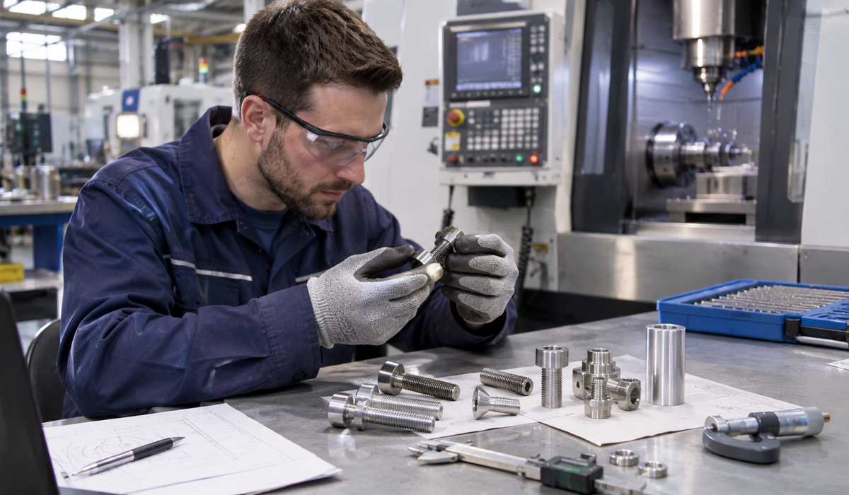
Sample Validation, Batch Consistency, and OEM RFQ Execution
Juxin Fasteners supports industrial batch production of custom machined fasteners and precision components through drawing review, First Article Inspection (FAI) sample verification, in-process dimensional control, and coordinated secondary operations (such as heat treatment, passivation, plating, or anodizing, performed via applicable internal or qualified partner processes per project plan). Procurement managers should account for specialty alloy sourcing, forming-die fabrication (if multi-process forming is selected), and secondary surface-finishing cycles when scheduling pilot builds and recurring supply programs.
To request a drawing-based DFM review and OEM quotation, send your technical package to info@juxinfasteners.com, or submit your drawings through our website. Please include:
Complete 2D engineering drawings (PDF) with revision level, CTQ tolerances, GD&T datums, thread classes, and surface roughness (Ra)
3D CAD models (STEP or IGES format)
Exact material grade, temper, heat-treatment hardness, and surface finish requirements (stating pre- vs. post-finish tolerance rules)
Assembly function, mating component materials, and operating environment
Required inspection documentation, prototype sample quantity, initial batch order size, and Estimated Annual Usage (EAU)
Contact Us
Tel.:
+86 020 8621 0320
+86 020 3121 6067
E-mail:
Technical Support:
Navigation
SEND INQUIREY