
Call Us
+86 136 6007 9809
Call Us
+86 136 6007 9809

Oct. 07, 2026
Thin sheet-metal equipment often needs permanent external threaded mounting points without adding a loose bolt from the opposite side of the panel.
This requirement appears across:
Semiconductor manufacturing equipment
Robotic automation systems
Motion-control equipment
Electronic enclosures
Electrical cabinets
Telecom equipment
Server chassis
Industrial machinery
Medical equipment
HVAC controls
Power electronics
A self-clinching stud can create a permanently retained male thread in suitable sheet metal through a mechanical press-in installation process.
JUXIN FASTENERS supplies self-clinching fastening components including:
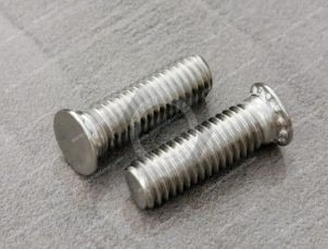
Self-clinching studs
Flush-head clinch studs
Carbon-steel clinch studs
Stainless steel clinch studs
Metric self-clinching studs
Miniature self-clinching fasteners
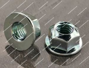
Self-clinching nuts
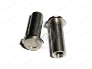
Self-clinching standoffs
Drawing-based custom self-clinching components
Self-clinching studs can provide an alternative to loose bolts, welded studs or other fastening methods where the sheet material, thickness and manufacturing sequence support clinching.
However:
A self-clinching stud should not be selected from thread size and stud length alone.
The parent sheet is part of the fastening system.
A self-clinching stud is a male threaded fastener mechanically installed into a prepared hole in suitable sheet material.
During press installation, the fastener's clinching geometry displaces surrounding sheet material into an undercut or retention feature.
After correct installation, the stud becomes mechanically retained in the sheet while its external thread remains available for assembly.
This can create a permanent male mounting point without requiring the assembler to insert a separate bolt through the panel during final assembly.
Depending on the design, a self-clinching stud can be useful where the opposite side of the panel should remain relatively flush or unobstructed.
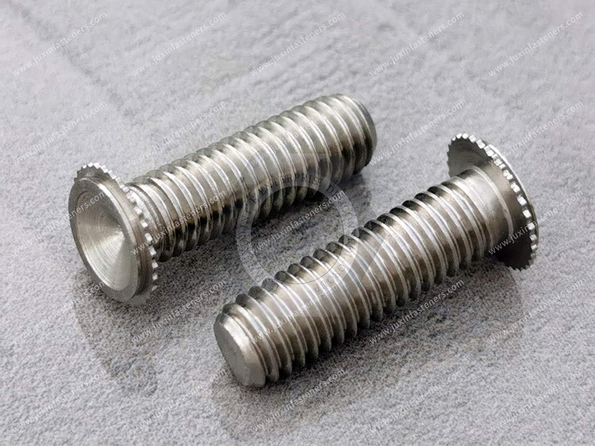
Thin sheet does not provide enough material thickness for many conventional tapped-thread applications.
A self-clinching stud solves a different problem.
Instead of cutting a male or female thread into the sheet, it integrates a separate threaded fastener into the panel.
Potential benefits include:
Permanent external threaded mounting point
Reduced loose hardware during final assembly
No welding operation for stud attachment
Installation during sheet-metal fabrication
Repeatable mounting position
Compatibility with automated or semi-automated assembly when appropriately designed
The actual benefit depends on the equipment architecture and production process.
Engineers often begin a fastener search with:
M4 self-clinching stud
or:
M5 × 20 clinch stud
That is understandable, but incomplete.
A better selection sequence is:
Sheet Material → Sheet Thickness → Sheet Hardness → Mounting Hole → Clinching Geometry → Thread → Stud Length → Surface Finish
Why?
Because the stud must first become mechanically retained in the parent sheet.
If the sheet cannot interact correctly with the clinching geometry, having the correct M5 thread does not solve the fastening problem.
Consider two products both described as:
M5 × 20 self-clinching stud
They may still differ in:
Head diameter
Head thickness
Clinching geometry
Mounting-hole requirement
Minimum sheet thickness
Material
Hardness relationship to the parent sheet
Surface finish
Thread tolerance
Installed projection
Therefore:
Thread diameter × stud length is not a complete substitution specification.
This matters for procurement teams qualifying alternate suppliers.
The existing fastener drawing and parent-sheet drawing should both be reviewed.
Self-clinching installation depends on controlled plastic deformation of the parent sheet.
During installation:
The stud is positioned in a correctly sized mounting hole.
A press applies controlled axial force.
Clinching features displace material around the mounting interface.
Sheet material flows into the fastener's retention geometry.
The installed stud becomes mechanically retained in the panel.
This is a mechanical joining process.
No welding heat is required for the stud-to-panel attachment.
However, successful installation depends on:
Fastener geometry
Sheet material
Sheet hardness
Sheet thickness
Hole dimensions
Installation force
Tooling
Anvil support
Sheet thickness affects whether sufficient parent material is available to engage the clinching geometry.
If the sheet is too thin for the selected fastener:
Retention may be inadequate
Panel deformation may increase
The stud may not seat correctly
If the fastener is not designed for the actual sheet thickness, increasing press force is not a reliable solution.
The fastener and sheet should be matched before production.
Sheet hardness can be as important as sheet thickness.
Self-clinching installation requires the parent material to deform around the retention features.
If the sheet is too hard relative to the selected stud:
Material flow may be insufficient
Installation may be incomplete
Fastener damage may occur
Panel damage may occur
Retention can be compromised
Therefore:
Two panels with identical thickness but different materials may require different self-clinching fastener solutions.
Cold-rolled steel sheet is widely used in:
Electrical cabinets
Industrial enclosures
Automation equipment
Server chassis
Telecom equipment
Machinery panels
Self-clinching studs can be suitable where the sheet properties and fastener design are compatible.
The actual material grade and thickness should be confirmed during selection.
Stainless steel sheet creates a different clinching environment from lower-hardness sheet materials.
The designer should not assume that a clinch stud selected for ordinary carbon steel will automatically install correctly into stainless steel.
Important considerations include:
Stainless grade
Sheet hardness
Sheet thickness
Fastener material
Clinching geometry
For stainless sheet applications, a compatible fastener design should be selected specifically for that substrate.
Aluminum is widely used in:
Electronics
Semiconductor equipment
Automation systems
Communication equipment
Lightweight enclosures
When specifying a clinch stud for aluminum, engineers should consider:
Aluminum alloy
Temper
Sheet thickness
Fastener material
Mechanical loading
Surface finish
Environmental exposure
Two aluminum sheets of equal thickness can behave differently if their alloy or temper differs.
This distinction becomes important during supplier substitution.
An installation validated in one aluminum alloy and temper should not automatically be assumed equivalent in another.
For critical applications, the actual substrate specification should travel with the fastener requirement.
The mounting hole is a functional dimension in a self-clinching joint.
If the hole is too small:
The stud may not enter correctly
Clinching features may be damaged
Installation force can increase
If the hole is too large:
Material engagement can be reduced
Position control may worsen
Retention can decrease
Hole diameter and tolerance should therefore be controlled on the sheet-metal drawing.
The production team should not treat the hole as a generic clearance hole.
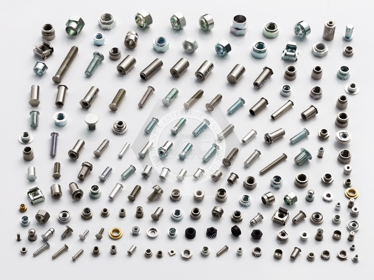
Hole preparation can also affect installation.
Important factors can include:
Punching
Drilling
Laser cutting
Burr condition
Hole roundness
Edge condition
Where a specific hole-preparation method or installation orientation is required, it should be defined during manufacturing planning.
The fastener supplier cannot compensate for an uncontrolled mounting interface simply by increasing installation force.
A clinch stud installed close to a sheet edge or large cutout has less surrounding material available to support installation.
Insufficient edge distance can contribute to:
Local panel deformation
Edge bulging
Reduced retention
Cosmetic damage
This is especially relevant in densely packaged electronic and automation enclosures where studs compete for space with:
Ventilation openings
Cable cutouts
Connectors
Adjacent fasteners
Panel bends
Edge distance should be considered before the enclosure drawing is released.
Self-clinching studs are installed using controlled pressing.
The objective is not simply to apply maximum force.
Too little force can result in incomplete seating.
Excessive force can:
Deform the panel
Damage the fastener
Distort the mounting area
Damage tooling
The appropriate installation process depends on the selected fastener and parent sheet.
Self-clinching studs and welded studs both create permanent male threaded mounting points, but they use different joining mechanisms.
Uses mechanical deformation of the parent sheet.
Potential advantages can include:
No welding heat at the attachment point
No weld spatter from stud attachment
Integration into press-based sheet-metal fabrication
Reduced need for post-weld cleanup associated with the stud attachment process
Uses a welding process to join the stud to the structure.
It can be appropriate where:
The substrate and joint are designed for welding
Welding is already integrated into production
Press access is unavailable
The structure is not suitable for clinching
The correct choice depends on the panel and manufacturing process.
A self-clinching stud avoids thermal distortion caused specifically by stud welding.
But it still applies mechanical force to the panel.
If the sheet is thin, unsupported or incorrectly tooled, mechanical installation can create:
Local deformation
Dishing
Panel marking
Flatness change
Therefore, it is more accurate to say:
Self-clinching eliminates welding heat from the attachment process, but panel flatness still depends on fastener selection, sheet design and installation tooling.
This distinction matters in precision equipment.
Semiconductor production equipment can contain:
Electronic control enclosures
Motion-control modules
Sensor assemblies
Internal brackets
Cable-management systems
Power electronics
Equipment panels
Self-clinching studs may be considered where these structures use suitable thin sheet and require permanent external threaded mounting points.
Potential applications include mounting:
Control modules
Cable brackets
Sensors
Internal covers
Electronic assemblies
Lightweight structural brackets
However, semiconductor equipment requirements vary significantly by machine zone and process.
A fastener used in an external equipment enclosure should not automatically be described as suitable for a cleanroom-critical or process-critical location.
Semiconductor manufacturing often raises concerns about particles and contamination.
Self-clinching installation avoids welding spatter associated with stud welding.
But this does not automatically make a fastener or installation process “cleanroom certified.”
Particle performance can depend on:
Installation process
Surface finish
Cleaning
Packaging
Handling
Equipment location
Customer cleanliness specification
If a semiconductor OEM has particle-control or cleanliness requirements, those requirements should be defined separately.
Robotic systems and automation cells can contain:
Control cabinets
Servo-drive enclosures
Sensor modules
Safety equipment
Cable-routing brackets
Internal mounting plates
Operator-interface structures
Self-clinching studs can provide permanent threaded mounting points in sheet-metal structures where press installation is practical.
The correct stud should be selected according to the actual load and panel design rather than simply labeling the application “high vibration.”
Robotic equipment can experience:
Acceleration
Deceleration
Machine vibration
Repeated operating cycles
Transport vibration
But the presence of vibration does not mean that a self-clinching stud alone prevents joint loosening.
The stud provides the male thread and its attachment to the panel.
The final bolted joint also depends on:
Mating nut
Clamp load
Joint stiffness
Bearing surfaces
Tightening strategy
Locking method where required
Self-clinching retention and nut-loosening resistance are separate engineering issues.
A stud can remain firmly retained in the sheet while the mating nut loosens.
Conversely, the nut can remain tight while the stud-to-panel interface is overloaded.
These are different failure modes.
Engineering validation should distinguish between:
Stud retention in the sheet
and:
Mating nut retention on the stud
This distinction is particularly important in dynamic machinery.
Push-out resistance describes the axial force required to displace the installed stud from the parent sheet.
It can be affected by:
Stud geometry
Sheet material
Sheet thickness
Sheet hardness
Mounting hole
Installation quality
A push-out value from one sheet material should not automatically be applied to another substrate.
During assembly, tightening the mating nut applies torsional loading to the stud.
The stud-to-sheet interface must resist rotation sufficiently for the intended assembly process.
Torque resistance can depend on:
Clinching geometry
Sheet material
Sheet thickness
Installation quality
Push-out and rotational resistance should therefore be treated as different performance characteristics.
A number such as:
Push-out = X N
is incomplete without identifying the test configuration.
Useful performance data should also identify relevant conditions such as:
Fastener size
Fastener material
Sheet material
Sheet thickness
Installation condition
The parent sheet is part of the test specimen.
This is why generic strength claims for self-clinching fasteners can be misleading.
The exposed stud thread must work correctly with the mating nut.
Important characteristics can include:
Thread diameter
Pitch
Thread tolerance
Thread length
Thread damage
Plating buildup where applicable
Metric threads can reference applicable ISO thread systems when required by the drawing.
Inch-series threads can reference appropriate ASME requirements where applicable.
The exact thread tolerance should follow the customer drawing rather than being assumed universally.
Depending on product design and manufacturing process, external threads may be produced using appropriate thread-forming or machining methods.
The process should be selected according to:
Material
Geometry
Thread requirement
Production volume
Customer drawing
A supplier should not claim that every self-clinching stud uses one specific thread-manufacturing process unless that process is actually controlled for the part.
The functional requirement is the specified thread geometry and assembly performance.
The nominal overall stud length is not the only length that matters.
Engineers should consider:
Installed projection
Mating-component thickness
Washer thickness
Nut height
Required thread engagement
Clearance behind the assembly
A stud that is too short may not provide sufficient engagement.
A stud that is unnecessarily long can create:
Interference
Cable-clearance problems
Safety concerns
Packaging problems
The required projection should be calculated from the actual assembly stack.
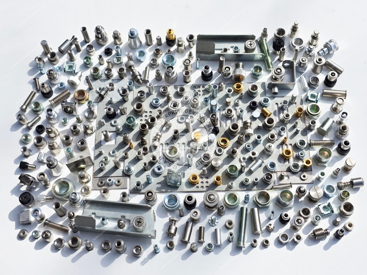
Selecting a 20 mm stud because “20 mm is standard” can create unnecessary protrusion.
A better sequence is:
Panel → Mounted Component → Washer → Nut → Required Thread Engagement → Additional Clearance
Then select the stud length.
This is particularly useful in compact electronics and automation equipment.
One important reason to use self-clinching studs is the ability to maintain a low-profile or flush condition on one side of the panel, depending on the specific stud design.
This can be valuable where the opposite panel surface:
Must remain unobstructed
Faces another component
Requires minimal protrusion
Has appearance requirements
The installed head condition should be confirmed from the actual product geometry and installation specification.
“Flush” should not be assumed from the generic term self-clinching stud.
Carbon steel can be suitable for many:
Industrial enclosures
Electrical cabinets
Server chassis
Automation systems
Equipment panels
Surface finish can be selected according to the application and customer specification.
Possible project requirements may include zinc-based or other specified protective finishes.
Corrosion performance should be tied to the actual coating specification.
Stainless steel can be selected where the project requires:
Stainless construction
Corrosion resistance
Material compatibility
Specific environmental performance
However:
304 or 316 should not be specified simply because the equipment is “high-tech” or used near a clean environment.
Material selection should follow the actual:
Corrosion environment
Sheet material
Cleanliness requirement
Customer drawing
Mechanical requirement
The clinching compatibility between stainless fastener and parent sheet must also be reviewed.
Surface treatment can affect:
Corrosion resistance
Appearance
Thread fit
Friction
Electrical behavior
Material compatibility
Potential project-specific finishes can include zinc-based coatings and other customer-specified systems.
If zinc-nickel or another coating is required, the coating specification and acceptance criteria should be defined.
A generic coating name should not automatically be associated with a fixed salt-spray performance.
ASTM B117 can be used as a salt-spray test method where specified.
But salt-spray exposure does not directly predict field service life.
A meaningful corrosion specification should define:
Coating system
Test duration
Evaluation criteria
White corrosion criteria where relevant
Red corrosion criteria where relevant
This is more useful than marketing a fastener using only a large salt-spray-hour number.
Equipment may combine:
Carbon steel
Stainless steel
Aluminum
Copper
Coated materials
When dissimilar metals are electrically connected in the presence of an electrolyte, galvanic corrosion can become a consideration.
This can matter in:
Outdoor equipment
HVAC systems
Industrial machinery
Humid environments
Some semiconductor support equipment
Material and coating selection should consider the complete assembly.
A metal stud may be used as part of an electrical bonding architecture in some equipment.
However:
A self-clinching stud does not automatically become a verified grounding stud simply because it is metallic.
Electrical performance can depend on:
Sheet coating
Contact surfaces
Stud material
Surface finish
Mating hardware
Clamp load
Equipment grounding design
If the stud is intended for protective bonding or grounding, the electrical requirement should be defined and validated separately.
A conventional through-bolt may be the simplest solution when both sides remain accessible.
A self-clinching stud becomes attractive when:
A permanent stud is useful
Loose-bolt handling should be reduced
One panel side should remain relatively flush
The stud can be installed during fabrication
A through-bolt may remain preferable where:
Both sides are easily accessible
Production volume is low
Permanent panel integration is unnecessary
The panel is unsuitable for clinching
The correct solution follows the manufacturing architecture.
The choice between these technologies should consider:
| Design Factor | Self-Clinching Stud | Weld Stud |
|---|---|---|
| Attachment method | Mechanical press installation | Welding |
| Welding heat | None from stud attachment | Present |
| Press access | Required | Not the same requirement |
| Parent sheet compatibility | Critical | Welding compatibility critical |
| Stud replacement | Generally not intended as field-removable | Generally permanent |
| Panel distortion risk | Mechanical installation must be controlled | Thermal effects must be controlled |
| Manufacturing integration | Sheet-metal press process | Welding process |
Neither should be selected from a marketing claim such as “stronger.”
The correct method depends on the structure and production process.
Both use clinching technology but provide opposite thread orientations.
Creates a permanent male external thread.
Creates a permanent female internal thread.
The choice depends on:
Assembly direction
Component geometry
Service sequence
Tool access
Desired hardware architecture
In the same enclosure, both may be used in different locations.
A standoff provides both:
Mounting interface
Controlled spacing
A stud primarily provides an external threaded mounting point.
If the mounted PCB or module requires a defined stand-off distance from the panel, a self-clinching standoff may be more appropriate.
If the component already contains the required spacing geometry, a stud may be preferable.
A self-clinching stud must be installed before the panel geometry blocks access to the required tooling.
This means manufacturing sequence matters.
Engineers should ask:
Is the panel flat during installation?
Has bending already occurred?
Can the press reach the location?
Is an anvil available behind the joint?
Will nearby flanges interfere with tooling?
A stud that works perfectly in the final CAD model may still be difficult to install if the production sequence is ignored.
This is especially important in complex cabinets.
If the clinch stud location becomes enclosed after bending, the production team may lose straight-line press access.
The engineering team may then be forced to:
Change tooling
Change assembly sequence
Change the fastener
Modify the panel
Reviewing fastener installation before releasing the bending sequence can prevent these changes.
Equipment panels can contain multiple studs for mounting one bracket or module.
The final assembly pattern depends on:
Hole-position tolerance
Stud geometry
Installation position
Panel deformation
Mounted-component hole pattern
If all mating holes are tightly constrained, tolerance accumulation can make assembly difficult.
The engineer should determine:
Which stud establishes location?
Which holes require clearance?
Where can tolerance be absorbed?
Whether a floating feature is needed elsewhere in the assembly?
This is a system-level tolerance decision.
For semiconductor equipment builders, useful questions include:
Is the stud inside or outside a controlled environment?
Is stainless material required?
Is particle control specified?
Is electrical bonding required?
Is the panel aluminum, stainless or coated steel?
Will the stud carry a bracket, electronic module or cable-management component?
Can the location be accessed by installation tooling?
These questions are more useful than simply requesting a “semiconductor-grade stud.”
There is no single universal fastener specification for all semiconductor manufacturing equipment.
For robotics and automation equipment, engineers should define:
Panel material
Dynamic loading
Mounted component mass
Stud orientation
Nut locking strategy
Service frequency
Environmental exposure
A clinch stud can solve the permanent male-thread requirement.
It does not independently solve every vibration or joint-loosening problem.
Self-clinching studs can also be used for:
Control modules
Brackets
Grounding architecture where separately validated
Cable supports
Internal frames
Covers
Power electronics
In these applications, designers should consider both mechanical and electrical requirements.
Server chassis and telecom cabinets may use self-clinching studs alongside:
Self-clinching nuts
Self-clinching standoffs
Cage nuts
Rivet nuts
PCB hardware
Each fastener should own a specific function.
For example:
Cage nut → removable rack mounting point
Self-clinching nut → permanent female thread
Self-clinching stud → permanent male thread
Self-clinching standoff → thread plus controlled spacing
Rivet nut → blind-side permanent threaded feature
This creates a more efficient enclosure fastening architecture than forcing one fastener type into every joint.
Self-clinching studs can also be considered for non-implant medical and laboratory equipment enclosures.
Potential applications include:
Internal brackets
Electronic modules
Control panels
Equipment chassis
Material, finish, cleaning and documentation requirements should follow the OEM specification.
The term “medical grade” should not be applied without a defined requirement.
HVAC control systems and building equipment can use sheet-metal enclosures containing:
Controllers
Sensors
Power modules
Electrical brackets
Covers
Self-clinching studs can provide permanent male mounting points where the panel and manufacturing process support clinching.
For humid or outdoor applications, corrosion requirements should be reviewed separately.
Design engineers should begin with:
1. What is the sheet material?
Carbon steel, stainless steel, aluminum or another material?
2. What is the sheet thickness?
Confirm compatibility with the selected fastener.
3. What is the sheet hardness or temper?
Particularly important for stainless steel and aluminum.
4. What mounting hole is required?
Use the selected stud specification.
5. What thread is required?
Metric or inch-series?
6. What installed stud length is required?
Calculate from the complete assembly stack.
7. What loads apply?
Axial, rotational, shear or combined?
8. Is the location accessible to installation tooling?
Review before finalizing panel bends.
9. What material and finish are required?
Base the decision on the actual environment.
This sequence is more reliable than beginning and ending with “M5 × 20 clinch stud.”
For accurate technical review and quotation, procurement teams should provide:
Thread size and pitch
Metric or inch thread
Stud length
Required installed projection
Fastener material
Surface finish
Sheet material
Sheet grade where known
Sheet thickness
Sheet hardness or temper where relevant
Mounting-hole diameter
Edge distance where restricted
Installed-head requirement
Required push-out performance where specified
Required torque resistance where specified
Corrosion requirement
Electrical bonding requirement where applicable
Prototype quantity
Annual production quantity
2D drawing
3D model where available
Inspection requirements
Packaging requirements
For an existing design, send both the stud drawing and parent-sheet drawing where possible.
Do not compare only:
M5 × 20 + stainless + price.
Compare:
Head geometry
Clinching geometry
Mounting-hole requirement
Sheet compatibility
Minimum sheet condition
Stud material
Thread
Thread length
Installed projection
Surface finish
Dimensional consistency
Installation behavior
Push-out requirement
Rotational resistance requirement
Drawing revision control
Sample approval
Production repeatability
Packaging
Two studs with the same thread and length may not be interchangeable.
When qualifying a second source, procurement and engineering teams should avoid approving the component from dimensional appearance alone.
A useful comparison should include:
Controlled drawing
Parent-sheet specification
Mounting hole
Installation process
Installed appearance
Thread fit
Required mechanical performance
Surface finish
Assembly evaluation
If the alternative fastener requires a different mounting hole, it may not be a true drop-in replacement even when its thread and stud length match.
Standard self-clinching studs cover many applications.
Drawing-based components may be required where the OEM needs:
Special stud length
Restricted head envelope
Special thread
Inch-series thread
Miniature geometry
Special material
Customer-specified finish
Application-specific clinching geometry
JUXIN FASTENERS supports standard and drawing-based self-clinching fastening components for industrial OEM applications.
Feasibility should be reviewed against the parent sheet and production process.
Before production release, a practical evaluation can include:
Mounting-hole confirmation
Installation trial
Installed-head inspection
Panel deformation review
Thread fit
Nut rundown
Assembly evaluation
Push-out testing where required
Rotational testing where required
The exact validation plan should follow the customer specification and application.
For drawing-based projects, a practical development path can follow:
Application Requirement → Parent Sheet Review → Stud Selection → Mounting-Hole Confirmation → Drawing Review
→ Prototype / Sample → Installation & Assembly Evaluation → Golden Sample Approval → Production
Where mechanical, electrical, cleanliness or corrosion testing is required, the acceptance criteria should be defined separately.
Applicable international standards may be referenced where relevant to:
Metric threads
Inch threads
Material specifications
Coating tests
Corrosion testing
Customer-specific requirements
However, many self-clinching fasteners are defined primarily by manufacturer or customer-controlled dimensions and application requirements.
The product should not be presented as universally compliant with every ISO, DIN, ASME, BS or EN standard.
The controlled drawing remains the primary technical reference for a custom part.
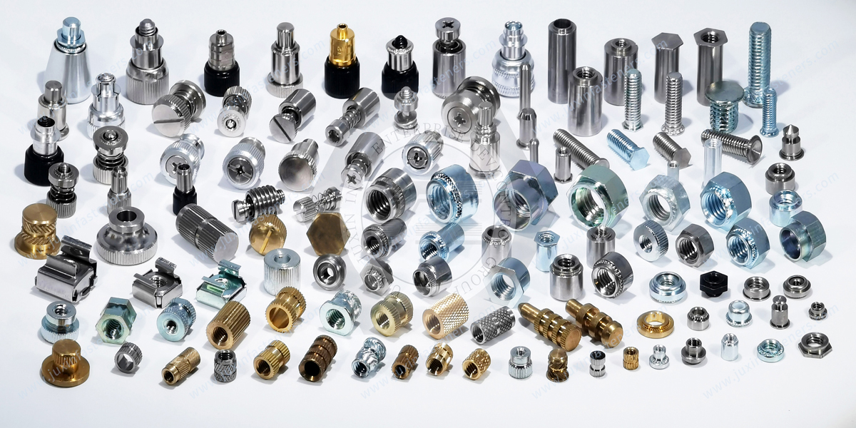
This page is a product-specific child page within the self-clinching fastener architecture.
Related solutions include:
Self-Clinching Fasteners for Telecom Cabinets & AI Data Center Enclosures — parent selection guide for clinching technology in thin-sheet equipment
Self-Clinching Standoffs for AI Server Chassis & Electronic Enclosures — permanent spacing and threaded PCB/module mounting
Self-Clinching Nuts for Thin Sheet Metal — permanent female threads in suitable sheet structures
Miniature Self-Clinching Fasteners — compact clinching hardware for dense electronics and equipment
AI Data Center Server Rack & Cabinet Fastening Solutions — complete rack, chassis and enclosure fastening architecture
Blind Rivet Nuts for Sheet Metal Enclosures & One-Sided Assembly — blind-side permanent threaded attachment
Projection Weld Nuts for Automotive Chassis & Sheet Metal Assemblies — welded female threads for fabricated structures
Weld Studs for Sheet Metal and Fabricated Structures — welded male threaded attachment where welding is appropriate
Internal linking should help engineers move according to the fastening decision:
Permanent male thread → Self-Clinching Stud
Permanent female thread → Self-Clinching Nut
Thread + controlled spacing → Self-Clinching Standoff
Blind-side thread → Rivet Nut
Replaceable rack thread → Cage Nut
Welded attachment → Weld Nut / Weld Stud
If you are designing or sourcing self-clinching studs for:
Semiconductor manufacturing equipment
Robotic automation systems
Motion-control equipment
Electrical cabinets
Electronic enclosures
Server chassis
Telecom equipment
Industrial machinery
Medical equipment
HVAC controls
Power electronics
send us your stud drawing, thread requirement, required stud length, parent-sheet material, sheet thickness, mounting-hole dimensions,
surface-finish requirement and estimated production quantity.
If the application is still in development, send the parent-sheet drawing as well.
Reviewing the stud and sheet together helps determine whether the selected self-clinching architecture is appropriate before the enclosure design is released.
JUXIN FASTENERS can evaluate carbon-steel, stainless-steel, metric, miniature and drawing-based self-clinching stud configurations according to the actual sheet-metal and assembly requirements.
JUXIN FASTENERS
Website: www.juxinfasteners.com
Engineering & RFQ: info@juxinfasteners.com
 MORE NEWS
Contact Us
Tel.:
+86 020 8621 0320
+86 020 3121 6067
E-mail:
Technical Support:
Navigation
SEND INQUIREY