
Call Us
+86 136 6007 9809
Call Us
+86 136 6007 9809

Oct. 07, 2026
AI server chassis, GPU computing systems, telecom equipment, power electronics and HVAC control cabinets increasingly combine dense PCB assemblies with thin sheet-metal structures.
This creates a fastening requirement that is easy to underestimate:
How do you create a permanent mounting point and maintain a controlled spacing distance from a thin metal panel without adding loose nuts, washers and separate spacers?
A self-clinching standoff can integrate the threaded mounting point and spacing function directly into a suitable sheet-metal chassis.
JUXIN FASTENERS supplies self-clinching fastening components for electronic and industrial equipment, including:
Threaded self-clinching standoffs
Through-hole self-clinching standoffs
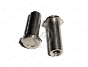
Blind self-clinching standoffs
Unthreaded standoff configurations
Miniature self-clinching standoffs
Carbon-steel standoffs
Stainless steel standoffs
Drawing-based custom standoff configurations
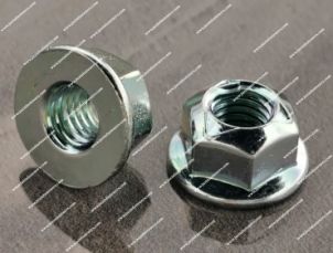
Self-clinching nuts
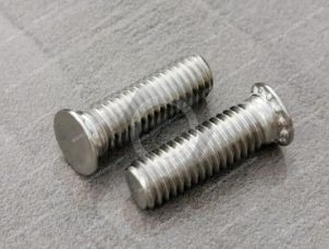
Self-clinching studs
Applications include AI server chassis, GPU server systems, telecom cabinets, PDU and UPS enclosures, HVAC control cabinets, industrial electronics and other thin-sheet equipment.
The correct standoff, however, should not be selected by thread and height alone.
Sheet material, sheet hardness, sheet thickness, mounting-hole geometry, edge distance, standoff height, PCB stack-up, installation access and final loading all matter.
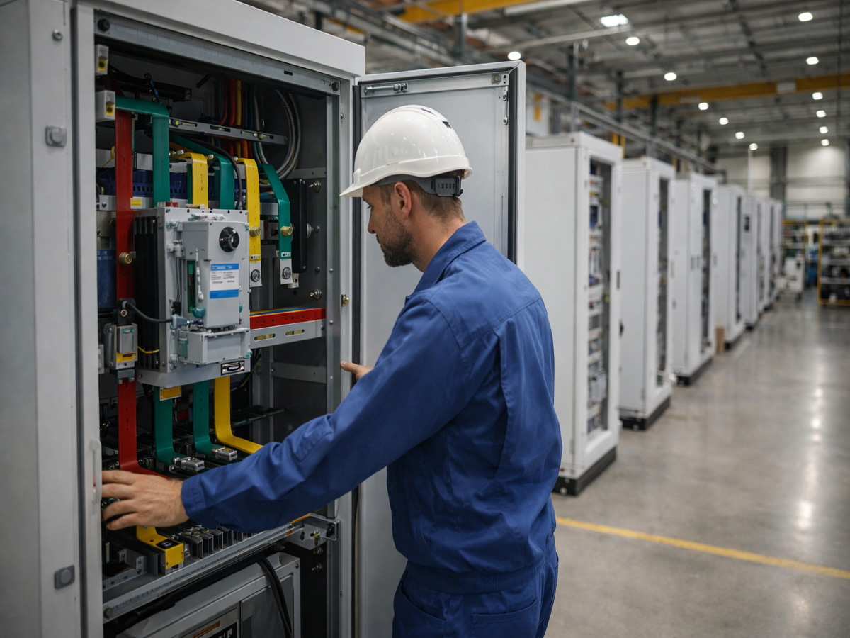
Self-clinching standoffs are useful where electronic or mechanical components must be positioned at a controlled distance from a sheet-metal panel.
Potential applications include:
Server motherboards
Control PCBs
Power management boards
Interface boards
Fan-control electronics
Internal brackets
Sensor modules
Power supply assemblies
As AI computing systems become denser, internal packaging space becomes increasingly valuable.
Integrating the mounting feature into the chassis can simplify the mechanical architecture compared with using separate loose spacers, nuts and washers.
Self-clinching standoffs can also be used in:
PDU enclosures
UPS systems
Power shelves
Power conversion equipment
Control electronics
Monitoring systems
Internal electrical modules
Potential applications include:
Network cabinets
Telecom chassis
Base-station equipment
Communication modules
Power electronics
Control boards
HVAC systems increasingly incorporate electronic controls, sensors, drives and communication modules.
Self-clinching standoffs can support:
Control PCBs
Variable-frequency drive electronics
Sensor modules
Communication boards
Power-control components
Internal mounting plates
Applications can include:
Automation controllers
Industrial computers
Machine-control systems
Power electronics
Instrumentation
Electrical cabinets
Robotics controllers
The common engineering requirement is a permanent mounting point plus controlled spacing in a sheet-metal structure.
A self-clinching standoff is pressed into a correctly prepared hole in suitable sheet metal.
During installation, the parent sheet material flows into the fastener's retention geometry.
This creates a mechanical interlock between the standoff and the panel.
Depending on the product design, the clinching geometry may include features such as:
Annular grooves
Undercuts
Displacer features
Anti-rotation geometry
Once installed, the standoff can provide:
A threaded or unthreaded mounting point
A controlled spacing height
A permanent attachment to the panel
Reduced dependence on loose mounting hardware
But the standoff's retention depends on the compatibility between the fastener and the parent sheet.
It should not be treated as a universal press-in component.
Engineers often specify a standoff mainly by its thread.
For example:
M3 self-clinching standoff
But the standoff performs two separate functions:
1. It provides a mounting interface.
2. It establishes a spacing distance.
This means standoff height can be just as functionally important as thread size.
The height can influence:
PCB clearance
Connector alignment
Cable routing
Component clearance
Cooling airflow
Board-to-panel spacing
Assembly stack-up
Access to nearby components
A small height change can affect the electronic enclosure even when the thread remains unchanged.
A common mistake is to select a self-clinching standoff from thread and height, then attempt to install it into whatever panel material has already been specified.
The better engineering sequence is:
Sheet Material → Sheet Thickness → Sheet Hardness → Mounting Hole → Standoff Type → Height → Thread
Why?
Because self-clinching installation depends on controlled displacement of the parent sheet.
If the sheet cannot flow appropriately into the retention geometry, the standoff may not install or retain as intended.
Two panels can have the same nominal thickness but behave differently during clinching.
For example:
Cold-rolled steel
Galvanized steel
Stainless steel
Aluminum
can have different material characteristics.
Therefore:
“1.0 mm sheet” is not a complete standoff specification.
The engineer should identify the actual sheet material and, where relevant, hardness or temper condition.
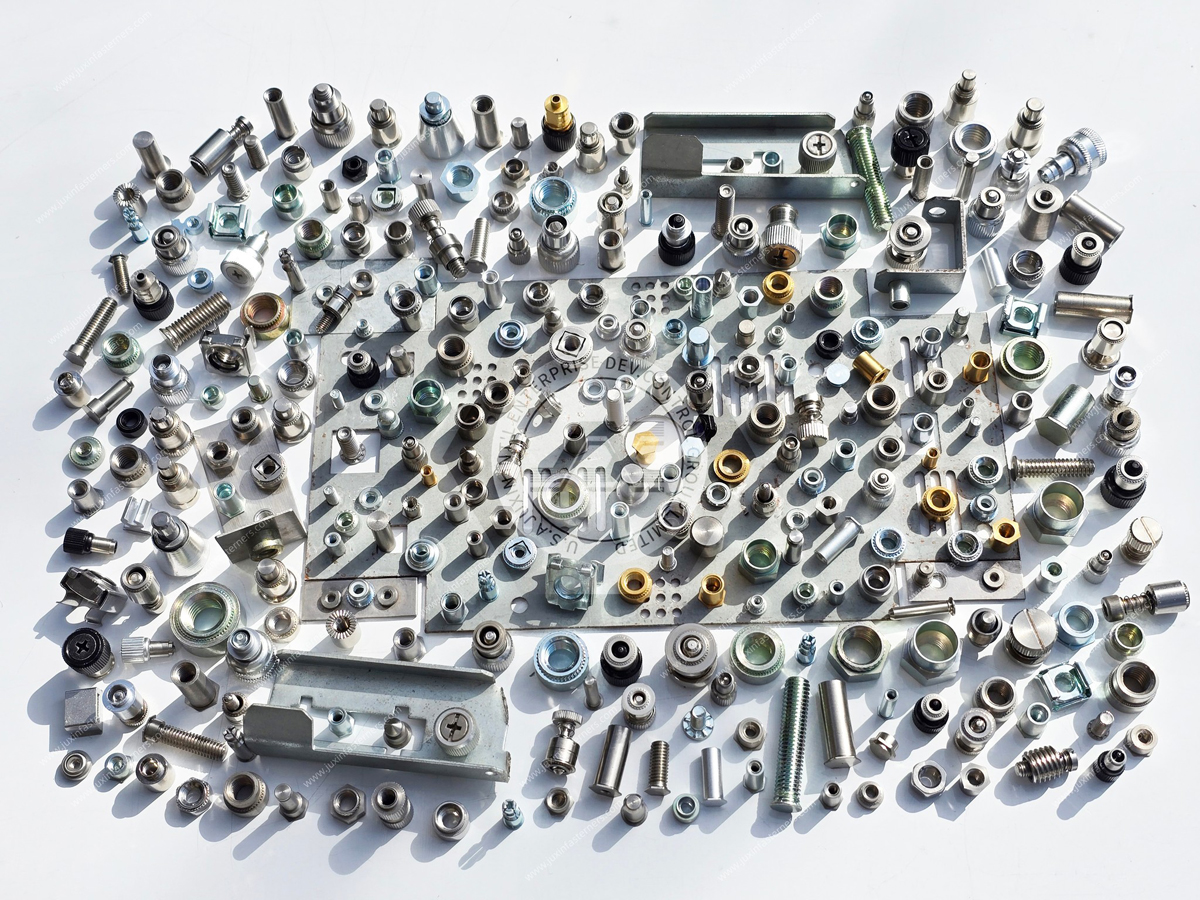
Self-clinching technology depends on the relationship between the fastener and parent material.
If the panel is too hard relative to the fastener design, sufficient material flow into the clinching features may not occur.
Potential consequences include:
Poor retention
Incomplete installation
Panel damage
Fastener damage
This is particularly important when a design changes from one sheet material to another.
A standoff validated in one panel material should not automatically be assumed suitable for a different material simply because the thickness is unchanged.
The mounting hole controls the interface between the standoff and sheet.
Important parameters can include:
Hole diameter
Hole tolerance
Hole quality
Burr condition
Hole location
Edge distance
A hole that is outside the intended dimensional range can affect:
Installation
Push-out resistance
Torque resistance
Standoff alignment
Panel flatness
The mounting-hole specification should therefore be controlled on the sheet-metal drawing.
It should not be left as an undefined fabrication detail.
Electronic chassis designs are often densely packaged.
PCB mounting points may be positioned close to:
Panel edges
Ventilation openings
Cable cutouts
Connector openings
Adjacent fasteners
If a self-clinching standoff is installed too close to an edge or large opening, the panel may not provide enough surrounding material to support the clinching process.
Potential problems include:
Local panel distortion
Edge bulging
Reduced retention
Cosmetic deformation
Edge distance should therefore be reviewed before releasing the enclosure drawing.
Self-clinching standoffs are designed for controlled pressing.
They should not be treated like impact-installed fasteners.
Installation conditions can influence:
Material flow
Standoff seating
Panel flatness
Retention
Alignment
The production process should consider:
Press access
Installation direction
Supporting anvil
Tooling geometry
Fastener orientation
Assembly sequence
The correct fastener can still perform poorly if the installation process is unsuitable.
Self-clinching standoff retention is often discussed using two terms:
Push-out describes resistance to axial force attempting to remove the standoff from the sheet.
Torque-out describes resistance to rotation of the standoff within the sheet.
These are different loading conditions.
A PCB mounting application may create one combination of axial and rotational loads, while a bracket or module mounting point may create another.
Therefore:
A single generic “standoff strength” value is not enough to describe application performance.
The required validation should match the actual joint.
Through-hole standoffs provide an open passage through the standoff.
Depending on the configuration, they can support:
Screw access
Component alignment
Through-fastening
PCB mounting
Equipment stacking
Potential applications include:
Server motherboards
Power electronics
Control PCBs
Telecom modules
Industrial electronics
The designer should verify whether the assembly requires an internally threaded standoff, an unthreaded passage or another configuration.
A blind standoff has a closed end rather than a continuous through-hole.
Blind configurations can be useful where the designer wants to:
Prevent a mating screw from passing completely through the standoff
Control screw penetration
Separate the threaded cavity from the opposite side
Protect nearby components from excessive screw length
This can be particularly useful where sensitive electronics or other components are located behind the mounting point.
However:
A blind standoff should not automatically be described as waterproof or dustproof.
Environmental sealing depends on the complete installed assembly.
Internally threaded self-clinching standoffs provide both controlled spacing and a reusable machine thread.
They are particularly useful for:
PCB mounting
Electronic modules
Internal brackets
Control boards
Equipment covers
Sensor assemblies
Thread selection should consider the mating screw and required engagement length.
Not every standoff requires an internal thread.
Unthreaded configurations can provide:
Spacing
Alignment
Support
Clearance
Through-hole mounting
These designs can be useful where a screw passes through the standoff or where the component architecture uses another retention method.
The correct choice depends on the complete assembly stack.
Compact electronics create demand for smaller fastening hardware.
Miniature self-clinching standoffs can be useful in:
Compact server electronics
Communication modules
Instrumentation
Medical electronics
Control modules
Small PCB assemblies
As the component becomes smaller, manufacturing and assembly tolerances become increasingly important.
There is less geometric margin for:
Hole-position error
Edge-distance error
Height variation
Connector misalignment
Miniature fastening systems should therefore be evaluated early in the enclosure and PCB design.
A PCB mounted to multiple chassis standoffs creates a tolerance stack involving at least:
Sheet-metal hole positions
Standoff installation positions
Standoff geometry
PCB mounting-hole positions
PCB dimensions
Connector positions
If each mounting point is treated independently, accumulated tolerance can create assembly stress.
Potential symptoms include:
Difficult screw installation
Board bending
Connector misalignment
Forced assembly
The correct response is not automatically to loosen every dimensional tolerance.
Instead, engineers should determine:
Which feature establishes primary location?
Which holes need clearance?
Where should positional tolerance be absorbed?
Does the assembly require a floating feature?
This is a system-level tolerance problem, not simply a standoff problem.
When multiple standoffs support one PCB, height consistency becomes important.
However, PCB flatness depends on more than the standoff.
It can also be affected by:
Sheet-metal flatness
PCB flatness
Hole positions
Component stack-up
Screw tightening sequence
Applied clamp load
Therefore, a supplier should not claim that a precision standoff alone guarantees a stress-free PCB.
Instead, standoff height should be controlled as one contributor to the complete stack-up.
Metal standoffs may form part of an electrical bonding path in some electronic assemblies.
But:
A metal self-clinching standoff does not automatically guarantee chassis grounding or EMI performance.
Electrical behavior can depend on:
Panel coating
Paint
Plating
Oxide layers
Standoff material
Contact pressure
PCB pad design
Washer design
Ground architecture
Assembly condition
If the standoff is intended to participate in grounding or bonding, the electrical requirement should be defined and validated as part of the finished equipment.
Mechanical retention and electrical bonding are different engineering requirements.
AI servers, telecom equipment and industrial electronics can have demanding electromagnetic compatibility requirements.
A standoff may contribute to the mechanical and electrical architecture, but EMC performance depends on the complete enclosure system, including:
Chassis design
Seam geometry
Ground paths
Shielding
Cable routing
PCB layout
Connectors
Surface finishes
Therefore, the correct fastener can support the design but cannot independently guarantee EMI or EMC compliance.
A traditional assembly may use:
Screw
Spacer
Washer
Nut
A self-clinching standoff can sometimes integrate several functions into one permanently installed component.
| Design Condition | Self-Clinching Standoff | Loose Spacer Assembly |
|---|---|---|
| Permanent attachment to chassis | Yes, after correct installation | No |
| Loose hardware during initial assembly | Reduced | Multiple separate components possible |
| Controlled spacing | Integrated into standoff height | Determined by spacer |
| Press operation required | Yes | No |
| Serviceability | Thread remains available | Depends on complete hardware stack |
| Best use | Sheet-metal chassis with suitable press access | Assemblies where clinching is not practical |
The self-clinching solution is not automatically better.
It becomes attractive when the manufacturing process and enclosure architecture support it.
A welded standoff can provide a permanent mounting point but introduces a welding process.
Self-clinching standoffs use mechanical installation instead.
Potential reasons to consider self-clinching include:
Avoiding welding heat
Avoiding weld spatter
Reducing local thermal distortion
Integrating installation into sheet-metal fabrication
A welded solution may still be appropriate where:
Welding is already part of production
Parent material supports the process
Joint design favors welding
Press access is unavailable
The correct choice follows the manufacturing architecture.
Where only one side is accessible, a rivet nut may solve a thread-generation problem that a self-clinching fastener cannot conveniently address during final assembly.
However, if controlled spacing is also required, additional hardware may be needed.
A self-clinching standoff can be attractive when:
The sheet is accessible during fabrication
Press installation is available
Permanent spacing is required
A threaded mounting point is required
A rivet nut may be preferable when:
Only one side is accessible
The structure is already closed
Retrofit installation is required
These are different manufacturing solutions rather than competing versions of the same fastener.
Carbon-steel standoffs can provide an economical solution for many electronic and industrial chassis applications.
Surface treatment should be selected according to:
Corrosion environment
Parent material
Customer specification
Electrical requirements
Final enclosure finish
If the panel will be painted or coated after installation, the production sequence should also be considered.
Stainless steel standoffs may be considered where the application requires:
Stainless material
Corrosion resistance
Material compatibility
Customer-specified stainless construction
However, stainless sheet requires special attention.
Self-clinching performance depends on the relationship between the fastener and sheet material.
A standoff suitable for cold-rolled steel should not automatically be assumed suitable for every stainless steel panel.
Sheet grade, hardness and thickness should be identified during selection.
Aluminum chassis are common in electronic equipment because they can provide low weight and useful thermal characteristics.
When installing a self-clinching fastener into aluminum, engineers should consider:
Aluminum alloy
Temper
Sheet thickness
Fastener material
Retention requirement
Environmental exposure
Galvanic compatibility
A carbon-steel or stainless fastener installed into aluminum creates a mixed-metal interface.
If moisture is present, galvanic corrosion may need to be considered.
The finish on a self-clinching standoff can influence:
Corrosion protection
Electrical contact
Friction
Appearance
Compatibility with the enclosure
Possible requirements may include:
Zinc plating
Zinc-nickel plating
Stainless surface condition
Customer-specified finishes
Where salt-spray testing is required, the coating system and acceptance criteria should be specified.
A generic salt-spray-hour claim should not be substituted for the customer's actual corrosion requirement.
Consider two server chassis designs using the same M3 PCB mounting thread.
The sheet is flat and accessible before bending and final assembly.
A self-clinching standoff may integrate naturally into the fabrication process.
The mounting location becomes accessible only after the enclosure is fully assembled.
A different fastening technology may be more practical.
The thread requirement is identical.
The manufacturing sequence is different.
Therefore:
Fastener selection should follow the production sequence, not just the final CAD geometry.
This is particularly important for contract manufacturers and supplier-development teams evaluating alternate fastening methods.
Before releasing the sheet-metal drawing, verify:
Sheet material
Sheet thickness
Sheet hardness where relevant
Mounting-hole diameter
Hole tolerance
Edge distance
Installation direction
Press access
Tooling clearance
Standoff height
Internal thread or through-hole requirement
PCB clearance
Connector alignment
Surface-finish sequence
Electrical bonding requirement if applicable
Service access
This review can prevent late-stage changes after sheet-metal tooling and PCB layouts have already been released.
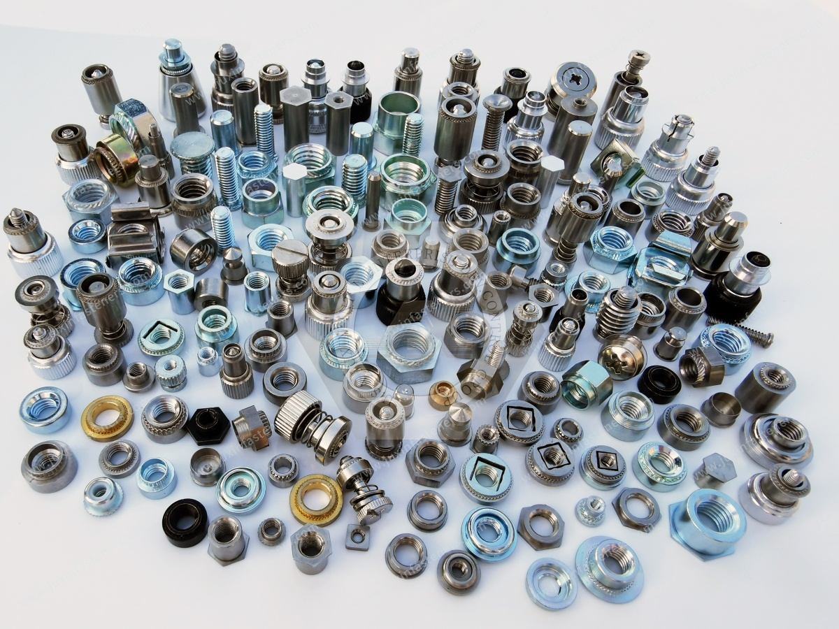
Design engineers should begin with these questions:
What is the parent sheet material?
Steel, galvanized steel, stainless steel or aluminum?
What is the sheet thickness and condition?
Confirm compatibility with the selected standoff.
What spacing height is required?
Determine this from PCB and enclosure stack-up.
What thread is required?
Metric, inch or unthreaded through-hole?
Should the standoff be through-hole or blind?
Consider screw penetration and component clearance.
Is the mounting point near a panel edge?
Check edge-distance requirements.
Can the location be accessed by a press?
If not, another fastening method may be more appropriate.
Does the standoff participate in electrical bonding?
If yes, define the electrical requirement separately from mechanical retention.
This selection path is more useful than searching only for “M3 PCB standoff.”
For accurate technical review and quotation, procurement teams should provide:
Thread size and pitch
Standoff height
Through-hole, threaded or blind configuration
Fastener material
Surface finish
Sheet material
Sheet thickness
Sheet hardness where known
Mounting-hole size
Edge distance where restricted
PCB or mounted-component information
Required push-out or torque-out criteria where specified
Electrical bonding requirement if applicable
Prototype quantity
Annual production quantity
2D drawing
3D model where available
Inspection requirements
Packaging requirements
For an existing design, sending the sheet-metal drawing as well as the standoff drawing can significantly improve technical review.
Do not compare only thread, height and unit price.
Important characteristics can include:
Material
Mounting-hole requirement
Clinching geometry
Height tolerance
Thread quality
Surface finish
Sheet compatibility
Push-out requirement
Torque-out requirement
Burr control
Dimensional consistency
Drawing revision control
Sample approval
Packaging
Production repeatability
A standoff can fit the same M3 screw and have the same nominal height while requiring a different mounting hole or sheet condition.
That difference matters in production.
Standard standoff configurations cover many applications.
Drawing-based custom components may be useful where the OEM requires:
Special height
Restricted outside diameter
Miniature geometry
Special thread
Inch-series thread
Blind configuration
Special through-hole
Custom material
Special surface treatment
Application-specific geometry
JUXIN FASTENERS supports standard and drawing-based self-clinching fastening components for electronic and industrial equipment.
For custom projects, the fastener drawing should be reviewed together with the parent sheet and mounted component.
A practical development path can follow:
Application Requirement → Sheet & Stack-Up Review → Standoff Selection → Mounting-Hole Confirmation → Drawing Review
→ Sample Installation → Mechanical / Assembly Evaluation → Golden Sample Approval → Production
If the standoff participates in grounding or another electrical function, that requirement should be validated separately within the finished equipment.
JUXIN FASTENERS supports server equipment manufacturers, data center infrastructure suppliers, telecom manufacturers,
HVAC equipment companies, electrical equipment manufacturers, contract manufacturers and industrial electronics OEMs.
This page is a product-specific child page within the self-clinching and electronic-enclosure fastening architecture.
Related pages include:
Self-Clinching Fasteners for Telecom Cabinets & AI Data Center Enclosures — selection guide for nuts, studs and standoffs in thin-sheet equipment
AI Data Center Server Rack & Cabinet Fastening Solutions — complete fastening architecture for server racks, GPU cabinets, PDU and UPS equipment
Self-Clinching Nuts for Thin Sheet Metal — permanent internal machine threads for suitable sheet-metal structures
Self-Clinching Studs for Electronic Enclosures — permanent male threaded mounting points
Miniature Self-Clinching Fasteners — compact hardware for dense electronic assemblies
Blind Rivet Nuts for Sheet Metal Enclosures & One-Sided Assembly — threaded installation where rear-side access is restricted
PCB Standoffs and Supports — metallic and engineering-plastic PCB mounting hardware
Nylon and Engineering-Plastic Fasteners — insulating screws, washers, spacers and PCB components
The parent pages should link into this self-clinching standoff page, while future detailed standoff pages should link back to it.
If you are designing or sourcing self-clinching standoffs for:
AI server chassis
GPU server systems
Data center equipment
Telecom cabinets
Network equipment
PDU enclosures
UPS systems
Power electronics
HVAC control cabinets
Industrial control systems
Automation equipment
Electronic enclosures
send us your 2D drawing, 3D model where available, thread requirement, standoff height, sheet material,
sheet thickness, mounting-hole specification and estimated production quantity.
If the project is still in the design stage, provide the PCB or mounted-component stack-up where possible.
JUXIN FASTENERS can evaluate threaded, through-hole, blind, miniature and drawing-based self-clinching standoff configurations according to the actual sheet-metal and assembly requirements.
JUXIN FASTENERS
Website: www.juxinfasteners.com
Engineering & RFQ: info@juxinfasteners.com
 MORE NEWS
Contact Us
Tel.:
+86 020 8621 0320
+86 020 3121 6067
E-mail:
Technical Support:
Navigation
SEND INQUIREY