Call Us
+86 136 6007 9809
Call Us
+86 136 6007 9809

Nov. 19, 2026
Serrated vs. Plain Flange Bolts for Coated Automotive Brackets
Automotive bracket joints are often specified by bolt diameter, property class and coating, while the underside of the flange receives less attention. Yet the choice between a serrated bearing face and a smooth (plain) flange can affect the bracket coating, installation friction, achieved clamp load and condition of the joint after service. The correct choice depends on the complete joint—not on a universal claim that either design is always more secure.
This guide focuses on a practical OEM decision: how should an engineering team compare serrated and plain hex flange bolts on the same coated automotive bracket before releasing a drawing or production order? It addresses e-coated, painted and powder-coated steel brackets, with additional considerations for aluminum components. Juxin Fasteners manufactures standard and made-to-drawing industrial fasteners and supports OEM review of geometry, material, coating and production requirements.
What Changes When the Flange Bearing Face Is Serrated?
A serrated flange has raised teeth or ribs beneath the head. Under installation load, these features can indent the mating surface and change resistance to relative rotation. A plain flange presents a smoother bearing area, although it can still compress, polish or damage a coating when the bolt is tightened. Neither design by itself guarantees retention of preload in a joint exposed to vibration, settling or thermal cycling.

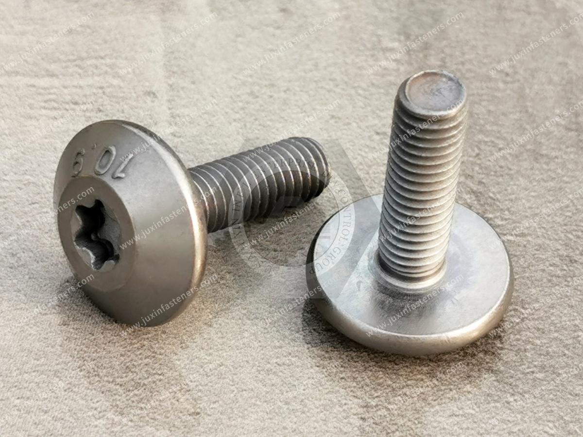
Serrations may be appropriate where the joint design deliberately permits local surface indentation and the resulting behavior has been validated. On a coated bracket, however, tooth penetration can locally remove or crack the protective film. A smooth flange may reduce concentrated indentation in some assemblies, but it can still exhibit coating compression, friction variation or embedment. The relevant question is not simply whether the teeth grip; it is whether the assembled joint meets the specified preload, corrosion and durability requirements.
Coated Steel Brackets: Surface Protection and Contact Pressure
E-coat, paint and powder coating differ in film thickness, hardness, adhesion and response to concentrated pressure. A serrated flange may cut through the coating at tooth contact points, while a plain flange distributes contact over a different area. In either case, a coating can crack or delaminate near the bearing face, particularly when the substrate or film is not sufficiently supported.
Coating damage is not automatically a corrosion failure, and an intact-looking surface is not automatically corrosion-proof. Risk depends on whether bare substrate is exposed, the surrounding coating system, water and salt exposure, crevice geometry and the joint's service environment. For production release, engineers should examine actual coated brackets after tightening, not infer corrosion performance from bolt geometry alone.
When the bracket is aluminum, additional issues include surface indentation, local material deformation, galling potential and galvanic compatibility with the selected fastener/coating system. The same bolt comparison should be repeated on representative aluminum joints rather than transferred directly from steel-bracket results.
Torque–Tension Scatter and Clamp-Load Consistency
Installation torque is consumed partly by thread friction and partly by friction beneath the bolt head or flange. Changing the flange bearing geometry can therefore change the torque–tension relationship, even when the nominal bolt size and property class remain unchanged. Coating thickness, lubricant topcoat, washer use, joint hardness, tool speed and installation sequence may also influence results.
A meaningful serrated-versus-plain comparison holds the other variables as constant as practicable: bolt diameter and length, property class, thread condition, fastener coating and lubrication, bracket substrate and coating, mating thread, and tightening equipment. The test should record the installation strategy and the measured clamp load or a validated proxy, rather than assuming that equal applied torque produces equal preload.
Engineers should evaluate the distribution of achieved clamp load across multiple assemblies, including low and high results—not merely an average. If a torque-angle strategy is used, its acceptance limits must be established for the specific joint. No single friction coefficient, tightening torque or clamp-load advantage can be promised for every serrated or plain flange bolt.
A Practical Side-by-Side Validation Plan
A useful OEM trial compares both flange designs on the same representative bracket configuration and records the following: (1) the pre-assembly coating condition and thickness where specified; (2) fastener and bracket material, surface finish and hardness; (3) installation torque, angle, tool and tightening sequence; (4) clamp-load results and scatter; (5) visible coating indentation, cracking or loss beneath the flange; (6) joint behavior after the specified mechanical and environmental exposure; and (7) the condition of the bearing surface after controlled removal.
Use a sample quantity and acceptance criteria justified by the application, and include production-representative parts where possible. Photography and dimensional measurements before assembly, after tightening and after removal help make results reviewable by engineering, production and purchasing teams.
Vibration and transverse joint movement require separate assessment. A serrated flange may alter local resistance to rotation, but the joint must still be evaluated for loss of clamp load and loosening under representative loading. If corrosion exposure is relevant, use the OEM-approved coating and corrosion test specification; salt-spray hours alone do not establish complete vehicle-service life.
Where a bracket will be disassembled and reassembled in service, repeatability matters. Assess whether the first installation changes the bearing surface or coating sufficiently to affect subsequent tightening. Reuse requirements must be specified rather than assumed.
Flange Geometry, Standards and Drawing Control
DIN 6921 and ISO 4162 are commonly referenced for metric hex flange bolts, but engineers must confirm the exact dimensional edition and relevant head, flange and wrench-clearance requirements. A standard reference does not, by itself, fully specify serration form, coating system, friction window or the acceptance criteria for a coated bracket. Do not assume that similarly named bolts from different standards or drawings are interchangeable.
For a made-to-drawing part, identify whether the flange underside is serrated or plain; define any critical flange diameter, head height, bearing-face condition and geometric tolerances; and state the fastener material/property class and thread requirements. Where a specific tooth pattern or bearing finish is essential, provide a drawing or validated sample rather than relying on a general product name.
The specified finish must be considered together with thread fit, friction requirements, corrosion performance and any risk controls relevant to high-strength fasteners. A zinc-nickel or zinc-flake coating is not a substitute for joint-specific verification. Any claim about coating durability, friction or hydrogen-embrittlement controls should be tied to the approved process and applicable OEM specification.
Manufacturing Feasibility for Automotive OEM Programs
Juxin Fasteners supports industrial batch manufacturing of standard and custom flange bolts according to the confirmed drawing and production volume. Available manufacturing approaches can include cold heading or cold forming, CNC machining and suitable secondary operations, with the process route determined for each product rather than assumed.
During feasibility review, the team can assess whether the requested flange geometry, serration detail, head clearance, thread tolerance and surface finish can be produced and inspected consistently. A cold-formed blank with selected secondary machining may be considered for some custom geometries, but no specific route is guaranteed without a drawing review.
For OEM programs, consistent dimensional inspection and traceability requirements should be agreed before quotation. Where specified, the validation plan may include first-article dimensions, coating verification, torque–tension testing, corrosion testing and production documentation. PPAP or other program-specific deliverables should be confirmed in scope rather than implied as universal for every order.
How Engineering, Production and Purchasing Teams Can Use the Results
Design engineers should decide which bearing-face geometry meets the joint's mechanical and coating requirements. Production managers need a tightening method that achieves repeatable clamp load without excessive damage or rework. Purchasing and supplier-quality teams should compare quotations against the same validated drawing, coating, inspection and documentation scope.
A lower bolt unit price does not necessarily reduce assembled-joint cost if it increases coating rework, tightening variation, tool adjustments or rejected assemblies. Conversely, an alternative flange geometry should not be rejected on appearance alone when controlled testing demonstrates that it meets the approved acceptance criteria. The decision should be based on documented joint performance and total production requirements.
OEM RFQ Checklist: Request a Drawing-Based Review
To request an engineering feasibility review and industrial batch quotation, send the following to info@juxinfasteners.com:
2D drawing (PDF) and available 3D model (STEP/IGES), including revision level and annual quantity.
Bolt size, thread, property class, material and applicable DIN/ISO/OEM specifications.
Required flange type (serrated or plain), flange dimensions and any underside geometry detail.
Bracket substrate and thickness, including steel or aluminum grade where known.
Bracket coating type, nominal thickness, specification and permitted bearing-face damage.
Fastener coating, lubrication/topcoat, corrosion and friction requirements.
Mating thread or nut, installation tool, tightening method and target clamp-load or torque–angle criteria.
Vibration, environmental, reuse, inspection and documentation requirements.
If both flange types are under consideration, identify the planned comparison and acceptance criteria. Juxin Fasteners can review the manufacturability and specification completeness of the requested components; final joint suitability must be validated by the OEM or responsible design authority under representative conditions.
Contact Us
Tel.:
+86 020 8621 0320
+86 020 3121 6067
E-mail:
Technical Support:
Navigation
SEND INQUIREY