
Call Us
+86 136 6007 9809
Call Us
+86 136 6007 9809

Oct. 14, 2026
Helical thread repair inserts provide an engineered method for restoring damaged internal threads and creating durable threaded connections in compatible metal components.
In industrial machinery, aluminum castings, gearbox housings, hydraulic equipment, automotive components, and precision mechanical assemblies,
damaged internal threads can cause equipment downtime, assembly failure, and expensive component replacement.
Thread damage may result from repeated maintenance, excessive tightening torque, cross-threading, insufficient thread engagement, corrosion, or mechanical overloading.
When the surrounding parent material remains structurally suitable, a helical wire thread insert can restore the original nominal internal thread size without requiring a larger mating bolt.
Helical inserts are also used in original equipment manufacturing to create threaded connections in materials where direct tapping may not provide the desired durability or service characteristics.
For mechanical engineers, manufacturing engineers, maintenance specialists, production managers, and industrial procurement teams,
successful installation requires more than choosing an insert with the correct nominal thread diameter.
The engineering process must consider parent material strength, existing thread damage, STI thread preparation, insert length, hole depth, installation tooling,
tang management, and the mechanical requirements of the completed joint.
JUXIN FASTENERS supplies industrial threaded inserts and drawing-based fastening components for OEM manufacturing and industrial maintenance applications.
This engineering guide explains helical insert selection, thread restoration in metal castings, installation methods, mechanical performance, inspection requirements, production considerations, and international B2B sourcing.
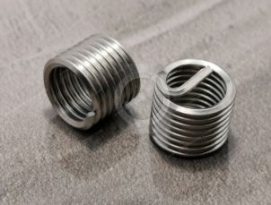
Helical thread repair inserts are precision-formed wire components designed to create internal screw threads within specially prepared receiving holes.
They are also known as:
Helical wire thread inserts.
Wire thread inserts.
Screw thread inserts.
Helical coil inserts.
Thread repair coils.
STI thread inserts.
The term STI refers to Screw Thread Insert and is commonly used when describing the special receiving threads and installation tooling required for wire thread inserts.
A helical wire insert is installed into a specially tapped internal thread in the parent material.
The insert forms a new internal thread that accepts a mating bolt or screw of the specified nominal size.
The outer surface of the wire coil engages with the prepared receiving thread.
The internal surface provides the functional thread profile for the mating fastener.
When correctly designed and installed, this arrangement can provide a serviceable threaded connection in suitable parent materials.
One major advantage of helical thread repair is the ability to restore the original nominal thread size.
For example, a damaged M8 × 1.25 internal thread may be repaired using a compatible M8 × 1.25 helical insert system.
The parent material must first be prepared using the appropriate STI drilling and tapping procedure.
After installation, the mating bolt remains M8 × 1.25.
However, the receiving hole is larger than the original tapped hole.
The repair is feasible only when sufficient surrounding material remains.
Helical inserts are used in two different engineering situations.
Thread repair: Restoring damaged internal threads in an existing component.
Original equipment installation: Creating specified threaded connections during manufacturing.
These applications may require different inspection, installation, and qualification procedures.
Helical inserts are commonly manufactured from formed wire with a specialized cross-sectional profile.
The wire geometry is designed to create the required internal and external thread engagement after installation.
Many conventional helical inserts use a rhombic or diamond-shaped wire cross-section.
The wire is formed into a helical coil corresponding to the required thread configuration.
The resulting geometry allows the installed insert to engage with the STI receiving thread while providing an internal thread for the mating fastener.
Austenitic stainless steel is commonly used for helical wire thread inserts.
Potential advantages include:
Corrosion resistance in suitable environments.
Compatibility with various industrial threaded assemblies.
Resistance to certain forms of wear.
Availability in multiple thread configurations.
However, stainless steel inserts are not universally suitable for every corrosive or high-temperature environment.
The actual alloy, surface condition, and service requirements must be confirmed.
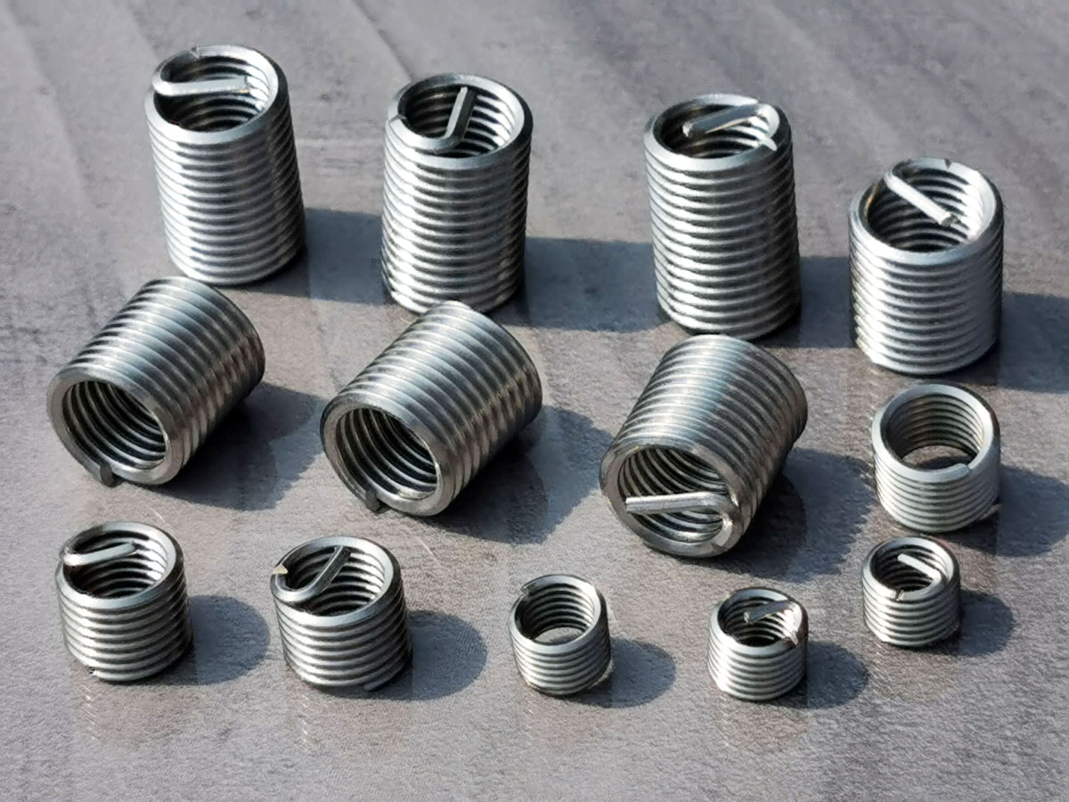
Specialized helical inserts may be manufactured from other materials for particular engineering requirements.
Potential selection factors include:
Operating temperature.
Corrosion exposure.
Parent material.
Mating bolt material.
Electrical requirements.
Mechanical loading.
Customer specifications.
Availability of alternative materials must be confirmed for the specific product.
The insert, parent material, and mating bolt form a combined mechanical system.
Material compatibility should be evaluated for:
Corrosion.
Galvanic interaction.
Thermal expansion.
Thread friction.
Mechanical strength.
Service temperature.
A stainless steel insert installed in aluminum may require additional corrosion evaluation in environments where moisture or electrolytes are present.
Two important helical insert categories are free-running inserts and screw-locking inserts.
These designs serve different engineering purposes.
Free-running inserts provide a conventional internal thread without an intentionally designed prevailing torque locking feature.
They are commonly used for:
Thread restoration.
General machinery.
Equipment housings.
Aluminum components.
Maintenance and repair.
Original equipment threaded connections.
The mating screw should engage according to the specified thread fit and assembly conditions.
Screw-locking helical inserts incorporate a locking feature designed to generate resistance to rotation of the mating screw.
Certain designs use one or more specially formed locking coils.
The locking mechanism must be compatible with the specified bolt and assembly requirements.
| Selection Factor | Free-Running Insert | Screw-Locking Insert |
|---|---|---|
| Primary function | Provide an internal thread | Provide an internal thread with locking interference |
| Prevailing torque | No intentional locking torque feature | Designed to generate prevailing torque |
| Common use | Thread repair and general threaded connections | Applications requiring a specified screw-locking function |
| Installation | Requires compatible STI preparation and tooling | Requires compatible STI preparation and product-specific tooling |
| Mating screw | Standard compatible thread | Compatible screw meeting locking requirements |
| Repeated assembly | Depends on materials and thread condition | Depends on locking design and applicable reuse criteria |
A screw-locking insert should not be selected solely because the assembly experiences vibration.
The complete bolted joint must still be designed for the required preload and loading conditions.
A locking feature does not automatically prevent all causes of joint relaxation or loss of clamp force.
Aluminum castings are widely used in industrial machinery, automotive components, pump housings, gearbox assemblies, and other engineered equipment.
Aluminum alloys may provide weight and manufacturing advantages, but internal threads can become damaged under unsuitable loading or repeated assembly conditions.
Potential causes include:
Excessive tightening torque.
Insufficient thread engagement.
Cross-threading.
Repeated assembly and disassembly.
Inappropriate bolt selection.
Material defects.
Corrosion.
Joint overload.
A properly installed helical insert can restore a compatible internal thread without changing the nominal mating bolt size.
This can reduce the need to redesign surrounding components.
In certain applications, a correctly engineered insert system may also improve the durability of the threaded connection compared with a direct thread in a relatively soft parent material.
However, the improvement depends on the specific design and must not be assumed.
Before repairing an aluminum casting, inspect the surrounding material for:
Cracks.
Porosity.
Previous repair damage.
Excessive hole enlargement.
Local deformation.
Insufficient wall thickness.
Damage to adjacent features.
A helical insert cannot restore the structural integrity of a cracked or otherwise unsuitable casting.
The receiving hole must have sufficient surrounding material to support the larger STI thread.
If the damaged hole has already been enlarged beyond the permitted repair geometry, a conventional helical insert may not be suitable.
Alternative repair methods or component replacement may be required.
Helical inserts may also be used in other compatible metallic materials.
Cast iron components may require thread repair following maintenance damage or mechanical overload.
Relevant considerations include:
Casting grade.
Material condition.
Hole geometry.
Existing damage.
Machining behavior.
Required joint strength.
Magnesium alloys are used in selected lightweight engineering applications.
Threaded insert selection must account for the material properties and corrosion environment.
Machining and repair operations involving magnesium also require appropriate material-specific safety procedures.
Helical inserts may be used in selected steel components where thread repair or another engineered threaded connection is required.
However, insert installation does not automatically improve the mechanical capacity of every steel threaded joint.
Helical inserts may be specified in CNC-machined components where serviceable internal threads or particular assembly characteristics are required.
The selection must reflect the actual parent material and design requirements.
One of the most important technical requirements in helical insert installation is correct preparation of the receiving thread.
A conventional tap used for the nominal mating screw is not interchangeable with the required STI tap.
An STI tap creates a specially dimensioned internal receiving thread for the helical insert.
The receiving thread is larger than the final nominal internal thread.
After installation, the insert provides the required internal thread for the mating bolt.
Suppose an aluminum housing contains a damaged M8 × 1.25 internal thread.
The repair process generally involves:
Assessing the damaged hole and surrounding material.
Preparing the hole to the specified STI drill size.
Tapping the receiving hole with the correct M8 × 1.25 STI tap.
Cleaning and inspecting the prepared hole.
Installing the compatible M8 × 1.25 helical insert.
Completing any required tang management.
Verifying the finished assembly according to the applicable procedure.
The final mating screw remains M8 × 1.25.
However, the receiving hole and STI thread dimensions differ from those of a standard M8 tapped hole.
Using a conventional M8 tap does not create the required receiving thread for an M8 helical insert.
The resulting geometry may prevent proper installation or retention.
The prepared STI thread should be checked using the appropriate inspection method and gauges specified for the insert system.
The correct STI thread geometry is essential to successful installation.
Drill selection is a critical part of helical insert installation.
The required drill diameter depends on the selected insert system and receiving thread specification.
A commonly used approximate tap drill calculation for ordinary metric threads is:
Tap drill diameter ≈ Nominal thread diameter − Thread pitch
This approximation is associated with conventional tapping and must not be used as the universal drill selection method for helical insert receiving holes.
STI receiving threads require their own specified drill dimensions.
The required drill size should be obtained from:
The applicable insert manufacturer's technical data.
The approved engineering drawing.
The specified STI thread standard.
The qualified repair procedure.
The correct drill size may also depend on the parent material and required thread engagement.
An oversized receiving hole may reduce insert engagement or retention.
An undersized hole may cause tapping problems or incorrect thread geometry.
The repaired thread must be aligned with the intended bolt axis.
Misalignment can cause:
Cross-threading.
Bolt interference.
Assembly distortion.
Uneven loading.
Installation difficulty.
Chips and contamination should be removed before insert installation.
Cleaning methods should be compatible with the parent material and equipment.
Insert length is an important design variable.
Helical inserts are often specified by nominal thread diameter and a length designation related to that diameter.
Common commercial designations may include:
1D.
1.5D.
2D.
2.5D.
3D.
Here, D refers to the nominal thread diameter.
For an M8 insert:
1D corresponds to a nominal length designation of 8 mm.
1.5D corresponds to a nominal length designation of 12 mm.
2D corresponds to a nominal length designation of 16 mm.
These examples explain the designation system and do not establish actual installed length tolerances or product availability.
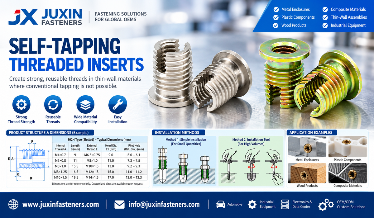
The selected insert must provide sufficient thread engagement for the required load.
However, longer inserts are not automatically better in every application.
The required length depends on:
Parent material strength.
Bolt strength.
Applied load.
Available hole depth.
Thread engagement.
Installation geometry.
Customer specifications.
Blind holes require adequate depth for:
Drilling.
STI tapping.
Insert installation.
Mating bolt engagement.
Any required tang clearance or removal.
A blind hole that is too shallow may prevent correct installation or cause the bolt to bottom out.
A fixed 1.5D or 2D recommendation should not replace engineering evaluation.
Insert length should be selected according to the actual joint requirements and approved product data.
The hole configuration affects tooling selection, installation depth, and tang management.
A through-hole provides access beyond the installed insert.
This may simplify certain installation and cleaning operations.
However, the installed insert must still be positioned correctly.
A blind hole has a closed end.
This creates additional requirements for:
Drill depth.
Tap depth.
Chip removal.
Insert length.
Installation tooling.
Tang clearance.
Bolt engagement.
If the mating bolt reaches the bottom of the hole before developing the intended clamp load, the joint may not function correctly.
The drawing should provide sufficient depth and clearance.
The required insert position relative to the surface must follow the selected insert specification.
The top coil should not be positioned arbitrarily.
Incorrect depth may interfere with assembly or reduce usable thread engagement.
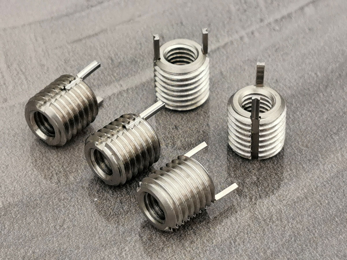
Many conventional helical inserts use a driving tang.
The tang allows the installation tool to rotate the insert into the prepared STI thread.
Step 1: Inspect the Parent Material
Confirm that the component is suitable for repair.
Step 2: Prepare the Receiving Hole
Drill or otherwise machine the hole according to the approved STI dimensions.
Step 3: Tap the STI Thread
Use the specified STI tap and appropriate machining procedure.
Step 4: Clean the Hole
Remove chips, debris, and contaminants.
Step 5: Inspect the STI Thread
Verify the receiving thread using the specified inspection method.
Step 6: Install the Helical Insert
Use a compatible installation tool and follow the required installation direction and depth.
Step 7: Manage the Tang
Remove the driving tang where required by the product and assembly specification.
Step 8: Complete Final Inspection
Verify the installation condition and required thread functionality.
The correct installation tool helps control the insert during insertion.
Incorrect tooling may cause:
Coil distortion.
Insert damage.
Incorrect installation depth.
Thread damage.
Installation difficulty.
Tang management is especially important in blind holes and assemblies where loose debris is unacceptable.
Some helical inserts use a tang that is designed to be removed after installation.
Where tang removal is required, the procedure must follow the product instructions.
Not universally.
The requirement depends on the insert design, application, bolt engagement, and approved installation procedure.
However, tang interference or loose fragments can create serious problems in certain assemblies.
Blind holes may make tang recovery more difficult.
The repair procedure should address:
Tang removal method.
Fragment recovery.
Inspection.
Contamination control.
Tangless designs use an alternative installation and removal interface.
Potential advantages include avoiding a break-off tang and reducing the need to recover a separated tang fragment.
However, tangless inserts require compatible tooling and product-specific installation procedures.
For hydraulic systems, precision equipment, and other contamination-sensitive assemblies, debris control is essential.
A tangless design may be considered, but the complete installation process must still be validated for cleanliness.
Helical inserts are often selected to improve the durability of threaded connections in suitable parent materials.
However, thread strength must be evaluated carefully.
The load-carrying capacity of an internal threaded connection depends on:
Parent material strength.
Thread geometry.
Engagement length.
Bolt strength.
Hole dimensions.
Insert design.
Installation quality.
Thread stripping occurs when the engaged threads cannot sustain the applied load.
In relatively soft parent materials, internal thread stripping may occur before the mating bolt reaches its intended mechanical capacity.
A properly designed helical insert system can provide a durable internal thread and may improve the performance of selected threaded connections.
However, the resulting strength depends on the complete assembly.
A helical insert does not automatically increase the strength of every threaded joint.
In some applications, the limiting failure mode may remain:
Parent material shear.
Casting fracture.
Bolt failure.
Insufficient engagement.
Local deformation.
Insert pull-out.
Where structural performance is important, engineers should evaluate the repaired connection under representative loading conditions.
Testing requirements should be established according to the application.
A helical insert installation should be evaluated as part of the complete threaded connection.
Insert pull-out may occur if the receiving thread or surrounding material cannot support the applied axial load.
Possible contributing factors include:
Incorrect STI thread.
Insufficient engagement.
Damaged parent material.
Excessive loading.
Incorrect installation.
The surrounding metal may fail even when the insert itself remains intact.
This is particularly important in thin-wall castings or components with limited material around the receiving hole.
In some designs, the mating bolt may be the limiting component.
The selected insert must therefore be compatible with the required bolt strength and joint design.
Improper installation or removal may distort the wire coil.
This can affect thread engagement and serviceability.
The mechanical capacity of the assembly should be based on the complete load path rather than an isolated claim about insert strength.
Helical inserts are commonly made from stainless steel, but corrosion performance depends on the entire assembly.
A stainless steel insert in an aluminum component may create a dissimilar-metal interface.
In the presence of moisture or another suitable electrolyte, galvanic corrosion may become a concern.
Important conditions include:
Humidity.
Salt exposure.
Cleaning chemicals.
Industrial fluids.
Outdoor weathering.
Temperature.
Service duration.
Depending on the application, engineering measures may include suitable coatings, sealants, material selection, or environmental protection.
Any treatment must remain compatible with the thread insert system.
Where required, corrosion testing should be specified using an appropriate method.
ASTM B117 may be relevant for specified salt spray testing.
However, salt spray exposure duration does not directly establish actual service life.
Helical inserts may be used in equipment exposed to elevated or changing temperatures.
Different materials expand and contract at different rates.
An aluminum housing, stainless steel insert, and steel bolt may respond differently to temperature changes.
Thermal cycling may influence:
Joint preload.
Thread contact conditions.
Material stresses.
Corrosion behavior.
Long-term serviceability.
The suitability of a helical insert depends on:
Insert material.
Parent material.
Mating bolt.
Applied loading.
Exposure duration.
Surface treatment.
Product specification.
A generic stainless steel insert should not automatically be assigned a universal high-temperature rating.
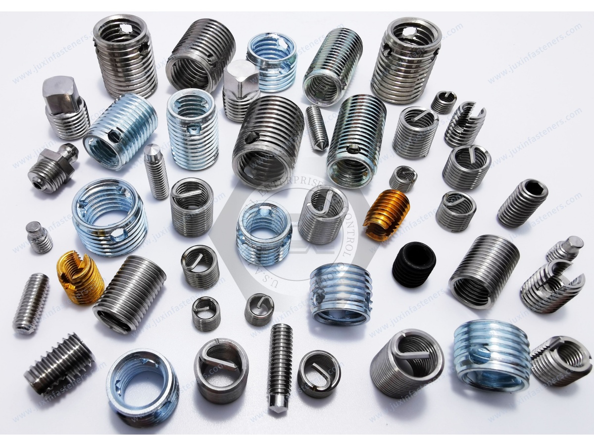
Helical inserts may be used in suitable aluminum housings and mechanical components where damaged internal threads require repair.
Engineering considerations include joint loading, temperature, parent material condition, and repair qualification.
Gearbox housings may require thread repair following maintenance or assembly damage.
The repair must preserve component alignment and structural integrity.
Hydraulic manifolds and equipment housings may contain threaded connections that require repair.
However, pressure-containing and sealing interfaces demand particular caution.
A helical insert does not automatically restore pressure integrity or sealing performance.
Selected threaded mounting points in pump and compressor housings may be suitable for repair.
The repair must be evaluated for vibration, mechanical loading, and material condition.
Helical inserts may be used in machinery housings, mounting structures, and serviceable threaded components.
Wire thread inserts may be specified during original equipment manufacturing to create threaded attachment points in suitable machined materials.
Maintenance operations may use helical inserts to restore damaged threads in selected equipment components.
The repair must be appropriate for the mechanical loads and service environment.
Helical inserts may be used in suitable metal housings and mechanical mounting components.
Electrical grounding or conductivity requirements must be evaluated separately where applicable.
Helical wire inserts are not the only available thread restoration solution.
Solid threaded inserts may be considered for certain repair applications.
Potential characteristics include:
Formed wire construction.
STI receiving thread.
Restoration of the nominal internal thread size.
Availability of free-running and locking configurations.
Solid inserts use a different construction and retention mechanism.
Depending on the design, they may incorporate external threads, locking keys, or other mechanical features.
| Selection Factor | Helical Wire Insert | Solid Thread Repair Insert |
|---|---|---|
| Construction | Formed helical wire | Solid threaded body |
| Receiving hole | Product-specific STI thread | Product-specific preparation |
| Retention | Engagement of wire coil with receiving thread | Depends on solid insert design |
| Installation tooling | Compatible helical insert tooling | Product-specific tooling |
| Wall thickness requirements | Depends on STI geometry | Depends on solid insert geometry |
| Repair suitability | Depends on remaining parent material | Depends on remaining parent material |
| Locking options | Free-running and selected screw-locking types | Depends on product design |
Neither design is universally superior.
The correct selection depends on:
Available material around the hole.
Existing damage.
Mechanical loads.
Installation access.
Repair tooling.
Service requirements.
Approved engineering procedure.
Possible causes:
Incorrect STI tap.
Wrong insert size.
Damaged receiving thread.
Incorrect installation tool.
Misalignment.
Recommended engineering review:
Verify the insert designation, STI thread preparation, and installation tooling.
Possible causes:
Incorrect installation technique.
Excessive installation resistance.
Damaged STI thread.
Incompatible tooling.
Incorrect insert selection.
Recommended engineering review:
Inspect the receiving thread and installation method before attempting another installation.
Possible causes:
Incorrect insert size.
Damaged internal thread.
Incorrect installation depth.
Tang interference.
Misalignment.
Thread contamination.
Recommended engineering review:
Check the installed insert condition, mating bolt specification, and required clearances.
Possible causes:
Incorrect receiving thread.
Insufficient engagement.
Parent material damage.
Excessive tightening load.
Incorrect repair procedure.
Recommended engineering review:
Assess the complete threaded connection and the condition of the surrounding material.
Possible causes:
Incomplete removal.
Incorrect removal tooling.
Inadequate cleaning.
Poor debris recovery.
Recommended engineering review:
Follow the approved tang management procedure and verify cleanliness.
Possible causes:
Incorrect original joint design.
Excessive tightening torque.
Insufficient material strength.
Inadequate repair geometry.
Misalignment.
Repeated overload.
Recommended engineering review:
Identify the original failure mechanism rather than repeating the same repair without further analysis.
Inspection should cover both the prepared receiving thread and the completed installation.
Relevant characteristics may include:
Insert designation.
Thread size.
Insert length.
Wire condition.
Coil geometry.
Surface condition.
Material specification.
The prepared hole should be inspected according to the applicable STI thread requirements.
The correct STI gauges or other approved inspection methods should be used.
Inspection after installation must follow the selected insert system and engineering requirements.
A conventional GO/NO-GO thread gauge procedure should not automatically be treated as sufficient for every installed helical insert.
Certain insert systems specify inspection of the STI receiving thread before installation and use different methods for verifying the completed assembly.
Where appropriate, functional verification may include:
Correct installation depth.
Visual condition.
Mating screw engagement.
Absence of installation damage.
Tang condition.
Required cleanliness.
Where required, mechanical testing should be performed according to a defined procedure.
Acceptance criteria must reflect the actual application.
OEM customers may request material identification, lot information, dimensional inspection records, or other documentation.
The availability of specific documentation must be confirmed for the selected product and order.
Helical thread insert selection should follow the applicable engineering drawing and relevant standards.
Metric thread specifications may reference ISO 68-1 for the basic thread profile, ISO 261 for selected metric thread sizes, and applicable ISO 965 provisions for thread tolerances.
However, the receiving STI thread requires its own specified geometry and inspection requirements.
UNC and UNF threads are commonly used in North American machinery and equipment.
ASME B1.1 is relevant to Unified inch screw threads.
The appropriate insert system and STI receiving thread requirements must be identified separately.
Applicable helical insert standards or customer specifications may include requirements based on the actual insert design, material, thread system, and intended application.
Relevant examples can include applicable NASM screw thread insert specifications where explicitly required by the customer.
The correct specification and edition must be verified rather than assumed.
An M8 × 1.25 thread and a 5/16-inch Unified thread are different systems.
Even where nominal diameters appear similar, pitch and thread geometry may differ.
M6 nominal diameter is approximately 0.2362 inches.
M8 nominal diameter is approximately 0.3150 inches.
M10 nominal diameter is approximately 0.3937 inches.
These are dimensional conversions only.
They do not establish compatibility with UNC, UNF, BSW, or BSF threads.
BSW and BSF are distinct British thread systems.
They should not be treated as interchangeable with ISO metric or Unified threads.
Special thread requirements should be submitted with drawings for technical review.
Helical inserts are used not only for repair but also in selected original equipment manufacturing processes.
Where helical inserts are specified during component manufacturing, the machining sequence may include:
Drilling.
STI tapping.
Cleaning.
Thread inspection.
Insert installation.
Final verification.
Production managers should consider:
Machining time.
Tool wear.
Hole location accuracy.
Installation tooling.
Insert feeding.
Inspection.
Rework.
Scrap prevention.
Certain insert systems may be compatible with automated installation equipment.
Compatibility depends on the product design, tooling, and production requirements.
Consistent receiving-hole dimensions and controlled installation are important to repeatable assembly.
The total installed cost may include:
Insert price.
STI drilling.
STI tapping.
Installation tooling.
Labor.
Inspection.
Scrap.
Rework.
Maintenance.
The lowest insert unit price does not necessarily provide the lowest total manufacturing cost.
Maintenance, repair, and operations purchasing teams often have different requirements from OEM production buyers.
A repair kit may include selected inserts and compatible tooling.
Depending on the product, the kit may contain:
STI tap.
Installation tool.
Tang removal tool.
Inserts.
Drill or drill-size instructions.
Kit contents vary and must be confirmed before purchase.
Bulk inserts may be appropriate for manufacturing operations or maintenance teams with established tooling.
Not every installation tool is compatible with every helical insert design.
Tang-type and tangless systems may require different tools.
Procurement teams should consider:
Frequently used thread sizes.
Insert lengths.
Free-running or locking configurations.
Maintenance frequency.
Tooling availability.
Packaging.
Replenishment requirements.
A product described simply as an M8 thread repair insert may not provide sufficient information.
The buyer should also confirm:
Thread pitch.
Insert length.
Insert type.
Installation method.
Tooling compatibility.
Material.
Applicable specification.
For industrial OEM purchasing teams, supplier qualification should address technical compatibility, quality requirements, and commercial reliability.
The supplier should receive a clear drawing or approved specification.
The insert material and any special surface requirements should be defined.
Critical dimensions and insert geometry should match the approved specification.
The insert must match the intended mating bolt and STI receiving thread system.
Packaging should protect inserts against damage and contamination during handling and transportation.
The required inspection and test documentation should be agreed upon before production.
Relevant requirements include:
MOQ.
Sample quantity.
Production quantity.
Estimated annual demand.
Lead time.
Packaging.
Delivery schedule.
Destination.
Actual supply terms and manufacturing feasibility must be confirmed during quotation.
Before approving a helical insert repair, engineers should complete the following evaluation.
Confirm the nominal diameter, pitch, and thread system.
Determine whether the original thread is stripped, worn, crossed, corroded, or otherwise damaged.
Check for cracking, porosity, deformation, and insufficient remaining wall thickness.
Confirm that the required STI receiving thread can be produced without compromising the component.
Choose free-running or screw-locking according to the application.
Evaluate parent material strength, required thread engagement, and available hole depth.
Verify STI drill size, STI tap, installation tool, and tang management requirements.
Establish receiving-thread inspection and completed installation acceptance criteria.
Where necessary, evaluate mechanical performance under representative loading conditions.
Record the approved repair method and relevant inspection results according to the customer's requirements.
A helical thread repair insert is a formed wire component installed into a specially prepared receiving thread to provide an internal thread for a mating screw or bolt.
Yes, in suitable applications where the surrounding aluminum remains structurally sound and sufficient material is available for the required STI thread.
A properly selected repair insert can restore the original nominal internal thread size while requiring a larger receiving hole in the parent material.
No. Conventional helical insert systems require the specified STI receiving thread and compatible tapping procedure.
Use the approved STI drill dimensions for the selected insert system.
Do not substitute the ordinary nominal-diameter-minus-pitch approximation.
These designations refer to nominal insert length relative to the nominal thread diameter.
A 2D designation represents a nominal length of twice the thread diameter.
Actual dimensions and suitability must follow the product specification.
They may improve performance in certain parent materials and joint designs.
However, strength improvement is not universal and depends on the complete assembly.
Tang removal requirements depend on the insert design and application.
The approved installation procedure must be followed.
A tangless insert uses an installation interface that does not require a conventional break-off driving tang.
Compatible tooling is required.
Yes, where the selected insert and tooling are compatible with the available depth and required clearance.
They may be suitable for certain cast iron components, subject to parent material condition, receiving-thread geometry, and mechanical requirements.
No. Corrosion resistance depends on the insert alloy, parent material, environment, and complete assembly.
They may be used in suitable mechanical threaded connections.
Pressure-containing or sealing interfaces require separate engineering evaluation.
Free-running inserts provide an internal thread without an intentional locking feature.
Screw-locking inserts incorporate a feature designed to generate prevailing torque on the mating screw.
No. Metric and Unified thread systems have different thread requirements and are not directly interchangeable.
Provide the insert type, thread size and pitch, length, material, applicable specification, tooling requirements, order quantity, and delivery requirements.
JUXIN FASTENERS supports international B2B sourcing inquiries for helical wire thread inserts, thread repair components, and drawing-based OEM threaded fastening requirements.
Whether your project involves aluminum castings, industrial machinery, gearbox housings, hydraulic equipment, automotive components, CNC-machined parts,
or industrial maintenance operations, correct insert selection and installation are important to reliable threaded connections.
For OEM manufacturing and MRO procurement inquiries, please provide:
2D engineering drawing or relevant technical specification.
Required nominal thread diameter and pitch.
Metric, UNC, UNF, or other specified thread system.
Free-running or screw-locking insert requirement.
Insert length designation.
Parent material grade.
Existing thread condition, for repair applications.
Available hole depth and surrounding wall thickness.
Blind-hole or through-hole configuration.
Applicable STI thread requirements.
Tang-type or tangless installation preference.
Required insert material.
Operating temperature and environmental conditions.
Mechanical loading requirements.
Inspection and quality documentation requirements.
Insert-only or tooling/kit requirements.
Prototype or sample quantity.
Initial production order quantity.
Estimated annual purchasing volume.
Packaging requirements.
Target delivery schedule and destination.
For nonstandard threaded insert requirements, please provide the relevant engineering drawings for technical feasibility review.
Our team can review the submitted requirements and confirm applicable product sourcing, manufacturing feasibility, and quotation arrangements.
Company: JUXIN FASTENERS
Website: www.juxinfasteners.com
Email: info@juxinfasteners.com
Contact JUXIN FASTENERS with your engineering drawings, technical specifications, and purchasing requirements to request a quotation for helical thread repair inserts,
stainless steel wire thread inserts, and related OEM threaded fastening components.
 MORE NEWS
Oct. 13, 2026
Contact Us
Tel.:
+86 020 8621 0320
+86 020 3121 6067
E-mail:
Technical Support:
Navigation
SEND INQUIREY