Call Us
+86 136 6007 9809
Call Us
+86 136 6007 9809

Precision machine tool spindles, grinding spindles, rotary tables and bearing-supported motion assemblies require accurate axial positioning of rotating components.
In these systems, the retaining nut is not merely a threaded component used to prevent axial movement.
Product Specification
Precision machine tool spindles, grinding spindles, rotary tables and bearing-supported motion assemblies require accurate axial positioning of rotating components.
In these systems, the retaining nut is not merely a threaded component used to prevent axial movement.
Its geometry, bearing-contact face, thread accuracy and locking mechanism can influence the installation and retention of the bearing assembly.
A poorly selected precision locknut may contribute to:
Incorrect bearing preload
Axial positioning errors
Uneven bearing-ring contact
Assembly runout
Thread damage
Loss of locking security
Difficult maintenance or readjustment
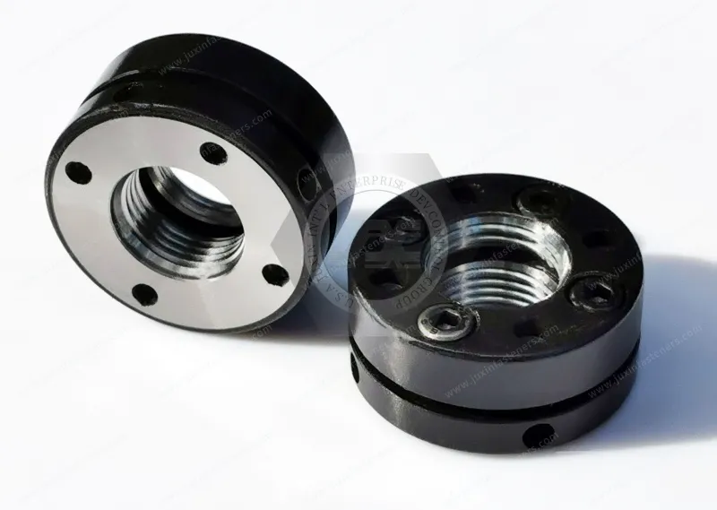
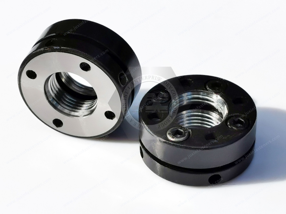
F-type precision locknuts are one category of precision bearing-retaining nuts associated with specific locking configurations used in spindle and rotary machinery applications.
However, the designation F-type is not a universal ISO or DIN dimensional classification.
Different manufacturers may use different naming conventions and locking constructions.
For OEM sourcing, the actual drawing and locking mechanism are more important than the product designation alone.
JUXIN FASTENERS supports precision machined locknuts, custom nuts and drawing-based fastening components for industrial machinery applications.
For F-type or thread-flank-locking precision nuts, exact geometry, locking construction, tolerances and manufacturing feasibility should be confirmed against the customer's specification.
This guide explains how to evaluate precision locknuts for spindle bearings, rotary tables and other rotating machinery assemblies.
An F-type precision locknut generally refers to a precision bearing-retaining nut identified by a supplier-specific product designation.
Depending on the design, the nut may incorporate:
A precision internal thread
A controlled bearing-contact face
A dedicated locking mechanism
Radial or axial locking elements
Special tool engagement features
Application-specific geometry
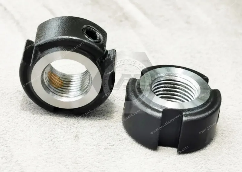
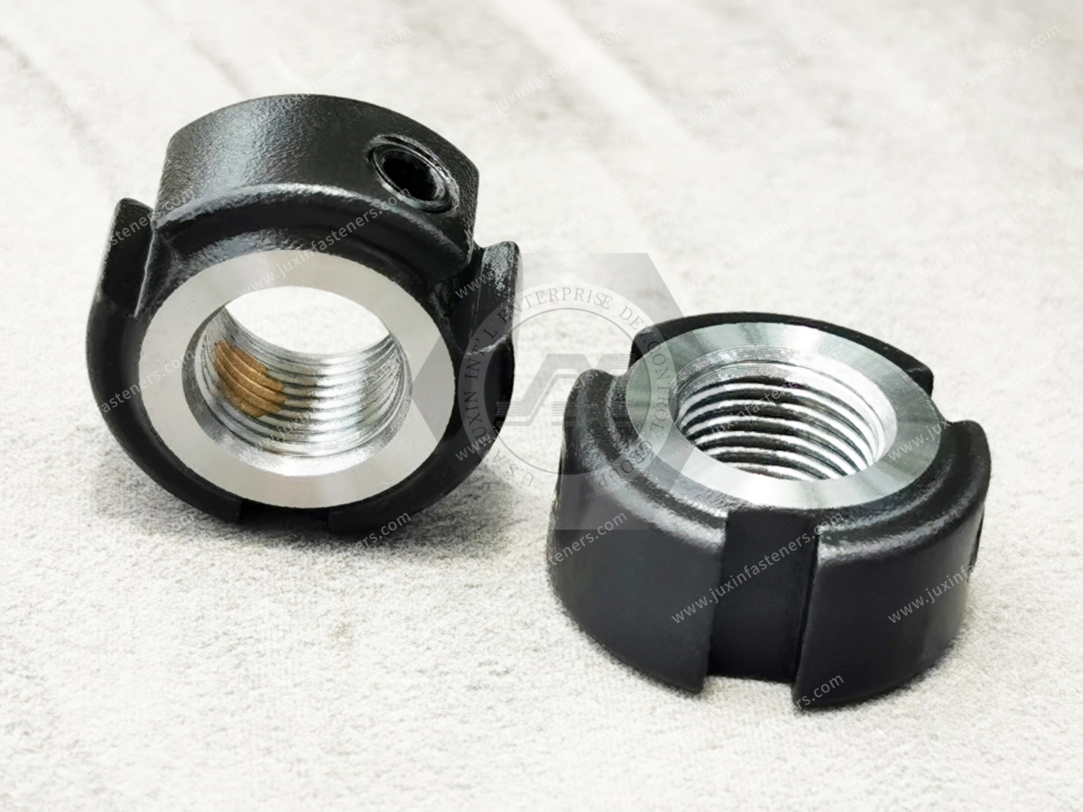
Some precision locknut systems use locking elements that act against the thread flanks.
Other designs use different locking methods.
Therefore, F-type should not be assumed to describe one identical locking mechanism across all suppliers.
For technical interchangeability, the OEM should identify:
Exact part number
Product drawing
Thread specification
Locking mechanism
Contact-face geometry
Tolerance requirements
Material and finish
A conventional locknut may primarily be selected to resist loosening in a threaded joint.
A precision bearing locknut may also perform an axial positioning or bearing-retention function.
Important requirements can include:
Bearing-contact face accuracy
Thread-to-face perpendicularity
Axial positioning
Locking security
Repeatable assembly
Compatibility with the spindle shaft
A standard hex locknut should not automatically be substituted for a precision bearing locknut.
The two components may have the same thread size but different functional requirements.
A precision locknut performs at least two distinct functions.
Function 1: Axial Positioning
The nut applies or retains axial force against the bearing stack or associated components.
Function 2: Rotational Locking
The locking mechanism resists unintended rotation of the nut relative to the shaft.
A nut may lock securely while its bearing-contact face is insufficiently accurate.
Alternatively, a precisely machined nut may provide good contact geometry but have an unsuitable locking mechanism.
For precision machinery, both functions must be evaluated.
Machine tool spindle assemblies may require controlled axial positioning of:
Angular contact bearings
Bearing inner rings
Spacers
Shaft shoulders
Other rotating components
The locknut may be part of the bearing clamping arrangement.
Its function depends on the spindle design.
For some assemblies, the locknut contributes directly to preload adjustment.
For others, bearing preload may be established through a separate arrangement.
Therefore, the locknut should be selected according to the actual bearing system.
Bearing preload depends on the complete assembly.
Potential influencing factors include:
Bearing arrangement
Bearing internal geometry
Shaft dimensions
Housing dimensions
Spacers
Temperature
Assembly procedure
Applied axial load
A precision locknut can influence preload, but it cannot guarantee constant preload under every operating condition.
The complete spindle design must be evaluated.
The bearing-contact face of a precision locknut may contact:
A bearing inner ring
A precision spacer
A retaining collar
Another axial locating component
If the contact face is not sufficiently perpendicular to the relevant thread axis, the load distribution may be uneven.
Potential consequences include:
Nonuniform axial contact
Bearing-ring distortion
Assembly runout
Increased sensitivity to tightening
Reduced positioning accuracy
The required face accuracy should be specified according to the spindle design.
Face runout and perpendicularity are related but not identical concepts.
A drawing may specify geometric tolerances controlling the relationship between the bearing-contact face and a defined datum.
The measurement method and datum structure must be clear.
For precision locknuts, the OEM should identify:
Datum reference
Thread axis definition
Bearing-contact face
Required runout or perpendicularity tolerance
Inspection method
A generic claim of zero runout is not technically meaningful.
A locknut may have a finely ground contact surface.
However, surface finish alone does not establish geometric accuracy.
The face must be controlled relative to the appropriate functional datum.
For example, a very smooth face may still be tilted relative to the threaded axis.
Therefore, engineers should distinguish between:
Surface roughness
Flatness
Perpendicularity
Axial face runout
Each controls a different aspect of the component.
The internal thread determines how the nut engages the spindle shaft.
Important parameters include:
Thread diameter
Thread pitch
Thread profile
Tolerance
Lead accuracy
Thread surface condition
For precision applications, the thread must be compatible with the actual shaft specification.
A nominally matching thread size does not guarantee functional interchangeability.
Thread clearance and manufacturing variation can influence how the nut seats under load.
The resulting relationship between the nut's contact face and the shaft may differ from the free-state geometry.
Therefore, a precision locknut should be evaluated in the context of its mating shaft.
For demanding assemblies, inspection of the individual nut may need to be supplemented by functional assembly verification.
Precision bearing locknuts may use different locking approaches.
Examples include:
Radial locking elements
Axial locking elements
Thread-flank locking elements
Mechanical locking features
Other proprietary or drawing-specific constructions
The correct design depends on the application.
Some precision locknut designs use locking elements intended to engage or load the thread flanks.
Depending on the construction, this may reduce direct point loading or marking compared with certain conventional locking methods.
However, actual shaft-thread protection depends on:
Locking element geometry
Contact pressure
Material hardness
Installation procedure
Locking torque
Thread condition
Thread-flank locking should not be described as universally damage-free.
Two products may both be described as thread-flank locking nuts.
But they may differ in:
Number of locking elements
Element geometry
Contact area
Adjustment method
Locking torque
Material
Shaft-thread interaction
The OEM should review the actual locking construction rather than relying on the product category alone.
Certain locking mechanisms can create localized contact stresses on the shaft thread.
Depending on the design and installation conditions, this may cause:
Surface marking
Thread deformation
Difficult disassembly
Reduced reusability
Damage to precision shaft components
For expensive spindle shafts, thread protection may be an important selection factor.
However, no locking mechanism should be assumed to eliminate all risk of damage.
A precision locknut may be removed and reinstalled during spindle maintenance.
But repeated use can affect:
Locking elements
Thread surfaces
Contact faces
Locking torque behavior
If reuse is required, the OEM should define:
Inspection criteria
Acceptable wear
Replacement conditions
Reassembly procedure
A product described as reusable should still be evaluated according to its actual design.
High-speed spindle systems generate heat during operation.
Temperature changes may affect:
Shaft length
Bearing geometry
Housing dimensions
Spacer dimensions
Axial preload
Contact conditions
The effect depends on the complete spindle assembly.
A precision locknut cannot independently compensate for all thermal expansion.
If a spindle assembly experiences excessive preload change due to thermal expansion, replacing the locknut alone may not solve the problem.
The engineer should review:
Bearing arrangement
Shaft and housing materials
Thermal growth
Spacer geometry
Lubrication
Assembly preload method
The locknut is one component in the system.
Rotary tables and precision indexing systems may experience:
Acceleration
Deceleration
Reversing motion
Vibration
Dynamic torque
The retaining nut must be suitable for the actual loading and locking requirements.
However, the locking mechanism should not be described as absorbing all reversing torque or guaranteeing constant clamping force.
The complete joint design determines load transfer.
In a rotary table, the main drive torque may be transmitted through other mechanical interfaces.
The bearing locknut may primarily provide axial retention.
Therefore, engineers should identify the actual load path before selecting the locknut.
The operating torque of the machine should not automatically be treated as the torque acting directly on the nut.
Precision locknuts may be manufactured from suitable steels or other specified materials.
Selection depends on:
Required mechanical properties
Machinability
Heat treatment
Wear
Thread behavior
Dimensional stability
Corrosion environment
JUXIN FASTENERS can review material requirements according to the actual drawing and manufacturing route.
A particular alloy steel grade should not be assumed for every F-type precision locknut.
Alloy steels may be considered where the design requires particular mechanical properties.
However, material designation alone does not establish:
Final hardness
Thread accuracy
Face runout
Locking performance
Dimensional stability
These characteristics must be specified and verified separately.
Heat treatment may be required for selected precision locknut designs.
Potential considerations include:
Hardness
Strength
Toughness
Distortion
Dimensional stability
The heat-treatment process should be matched to the material and functional requirements.
A precision locknut may undergo:
Rough machining
Heat treatment
Finish machining
Grinding
Thread finishing
Inspection
The actual sequence depends on the design.
If heat treatment introduces distortion, critical dimensions may require finishing afterward.
Therefore, the manufacturing plan should consider which dimensions are controlled in the final condition.
Potential finish requirements may include:
Black oxide
Protective coatings
Customer-specific surface treatments
The selected finish should consider:
Corrosion exposure
Dimensional requirements
Thread fit
Bearing-contact surfaces
Assembly friction
Black oxide should not be described as providing high corrosion resistance without considering the complete finish system and environment.
For precision locknuts, a coating or conversion treatment may influence:
Thread fit
Contact behavior
Friction
Dimensional condition
The drawing should define whether critical dimensions apply before or after surface treatment.
Where contact faces require a specific condition, the finishing process should be controlled accordingly.
| Selection Factor | F-Type / Supplier-Specific Precision Locknut | Conventional Bearing Locknut |
|---|---|---|
| Product designation | Supplier-specific | May follow established dimensional series |
| Locking mechanism | Depends on actual design | Depends on selected type |
| Face accuracy | Drawing-dependent | Product specification-dependent |
| Thread accuracy | Drawing-dependent | Product specification-dependent |
| Shaft protection | Mechanism-dependent | Mechanism-dependent |
| Interchangeability | Requires drawing review | Requires specification review |
| Typical selection basis | Precision application and locking requirements | Bearing retention and applicable standard |
The correct product should be selected by specification, not naming convention alone.
All-metal prevailing-torque lock nuts are designed to provide resistance to rotational loosening through mechanical thread interference or deformation.
Precision bearing locknuts may require additional geometric controls for axial bearing positioning.
These product families are not automatically interchangeable.
A nut suitable for vibration resistance may not provide the required bearing-contact accuracy.
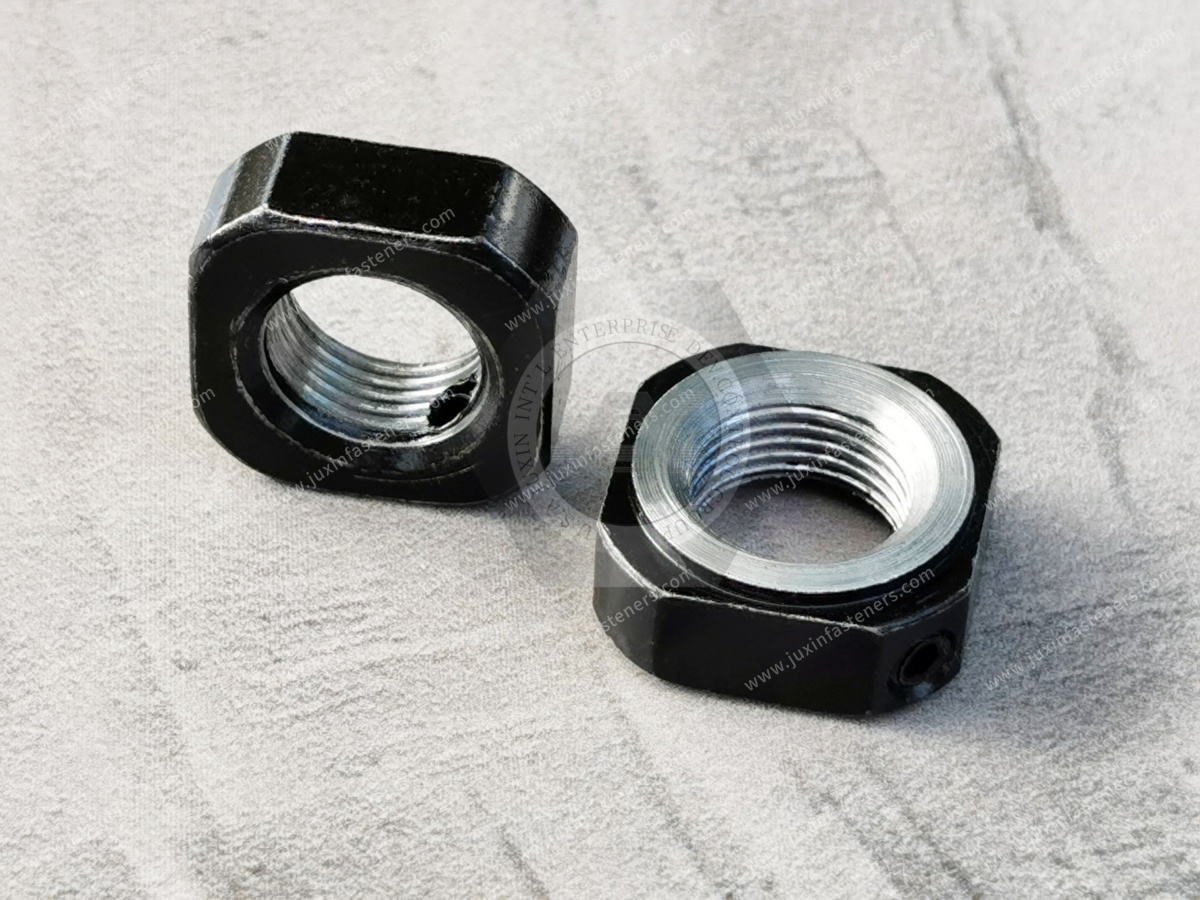
A custom machined nut may be appropriate where:
Standard geometry is unsuitable
Special threads are required
Restricted space is available
A unique locking mechanism is specified
Tight geometric tolerances are required
However, custom machining does not automatically establish precision bearing suitability.
The drawing must define the functional requirements.
For OEM development, a standard precision locknut may reduce:
Development effort
Tooling complexity
Supplier qualification work
Replacement-part risk
Custom geometry should be considered when the standard product cannot satisfy the application.
This helps balance engineering performance and long-term supply continuity.
Potential requirements include:
Accurate bearing positioning
Controlled axial contact
Secure locking
Compatible shaft threads
Serviceability
Dimensional stability
The nut should be selected according to the spindle bearing arrangement.
Grinding spindles may require high rotational accuracy.
Potential considerations include:
Bearing preload
Contact-face accuracy
Thread fit
Vibration
Thermal behavior
The locknut must be evaluated as part of the complete spindle system.
Rotary tables may require precision axial retention for bearing-supported rotating components.
Selection should consider:
Bearing arrangement
Axial loads
Locking mechanism
Installation access
Service procedure
The correct locknut depends on the actual assembly.
Ball screw support bearing assemblies may use precision locknuts for axial retention or preload adjustment.
Potential requirements include:
Thread compatibility
Contact-face accuracy
Axial positioning
Locking security
The assembly should be evaluated according to the bearing manufacturer's recommendations and the OEM design.
Precision automation systems may use custom machined nuts for:
Rotary axes
Bearing supports
Positioning mechanisms
Specialized motion components
The correct geometry and tolerance depend on the application.
Depending on the drawing, inspection may include:
Internal thread verification
Overall dimensions
Contact-face geometry
Runout
Perpendicularity
Surface roughness
Material verification
Hardness where specified
Locking mechanism evaluation
The inspection method should be agreed during technical review.
A drawing stating:
Face Runout: 0.005 mm
is incomplete unless the relevant datum and measurement conditions are clear.
The engineer should identify:
Which face is controlled
Which axis is the datum
How the part is supported
Whether measurement occurs in the free state or assembled condition
This is essential for meaningful supplier comparison.
Identify the spindle, rotary table or bearing-supported assembly.
Determine the locknut's role in axial positioning or preload.
Specify diameter, pitch and tolerance.
Identify the required geometric tolerance and datum.
Evaluate shaft protection, locking security and serviceability.
Specify the required grade and mechanical properties.
Identify hardness and dimensional stability requirements.
Consider corrosion and precision interface requirements.
Specify critical dimensions and functional tests.
Confirm compatibility with the actual spindle or rotary system.
For accurate technical review and quotation, provide:
Existing part number or reference
2D drawing
3D model where available
Thread size and pitch
Thread tolerance
External dimensions
Contact-face geometry
Runout or perpendicularity requirement
Surface roughness requirement
Locking mechanism details
Material specification
Heat-treatment requirement
Surface finish
Inspection requirements
Prototype quantity
Annual purchasing forecast
Required documentation
If replacing an existing precision locknut, provide the current product specification and mating shaft details where possible.
Two precision locknuts may have:
The same nominal thread
Similar external dimensions
Similar appearance
But differ in:
Locking mechanism
Contact-face geometry
Thread accuracy
Locking element travel
Installation procedure
Required tightening torque
Therefore, an alternative supplier should be qualified using the actual engineering requirements.
A nominal dimensional match is not sufficient.
A practical OEM qualification process may follow:
Existing Part Review → Drawing Review → Thread & Datum Verification → Locking Mechanism Review → Material Confirmation
→ Sample → Dimensional Inspection → Functional Assembly Test → Golden Sample Approval → Production
The OEM should define the acceptance criteria.
An approved sample should be linked to:
Drawing revision
Material specification
Heat-treatment condition
Surface finish
Critical dimensions
Locking mechanism
Required inspection results
This helps establish a controlled production reference.
Depending on the project, inspection and documentation may include:
Dimensional inspection
Thread verification
Material verification
Hardness testing
Surface roughness measurement
Geometric tolerance inspection
Locking mechanism evaluation
Additional inspection documents, including EN 10204 documentation where applicable, should be agreed during RFQ review.
Depending on the actual component, relevant references may include:
ISO metric thread specifications
ASME/ANSI inch-thread specifications
ISO 1101 for geometrical tolerancing principles
ISO 6508 series for Rockwell hardness testing where applicable
Applicable ISO or ASTM material specifications
EN 10204 for agreed inspection documentation
Customer-specific precision locknut drawings
The designation F-type should not be represented as a universal ISO or DIN standard without a specific verified reference.
JUXIN FASTENERS can review drawing-based requirements for:
Precision bearing locknuts
Custom machined nuts
Spindle retaining nuts
Special threaded collars
Nonstandard precision nuts
Application-specific locking components
The manufacturing route and locking mechanism should be confirmed according to the actual drawing.
A broader engineering guide to precision nut selection, machining and bearing-retention requirements.
Manufacturing process selection for drawing-based fasteners, including cold heading, CNC machining and hybrid production.
Mechanical locking solutions for vibration-sensitive threaded joints.
Drawing-based precision machining for specialized industrial components.
These related solutions help engineers distinguish between bearing-positioning precision, rotational locking and manufacturing process selection.
Are you sourcing precision locknuts for:
CNC machine tool spindles
Grinding spindles
Rotary tables
Ball screw support bearings
Precision motion assemblies
Industrial automation equipment
JUXIN FASTENERS can review drawing-based precision locknut and custom machined nut requirements for industrial OEM applications.
For efficient technical evaluation, send:
2D Drawing + Thread Specification + Contact-Face Tolerance + Locking Mechanism + Material + Surface Finish + Quantity
If you require an alternative to an existing F-type precision locknut, please include the reference part number and relevant assembly requirements.
The objective is to identify a precision locknut that satisfies the actual bearing-positioning, locking and inspection requirements—not merely one that matches the nominal thread size.
JUXIN FASTENERS
Website: www.juxinfasteners.com
Engineering & RFQ: info@juxinfasteners.com
Send your drawing and application requirements for technical review and quotation.
Product Packaging
Packaging Standard
At Juxin Fasteners, we apply standardized export packaging to ensure product protection, traceability, and compliance with international logistics requirements.
1. Standard Export Packaging
Unless otherwise specified, all products will be packed according to our factory standard export packaging, which includes:
Moisture-resistant inner protection
Poly bag or small box packing as required
Reinforced export cartons
Clear labeling with part number, specification, batch number, and quantity
Palletizing for sea or air shipment when necessary
Our standard packaging is designed to ensure safe transportation, efficient warehousing, and long-distance international shipping.
2. Customized Packaging Options
We also provide customized packaging solutions according to customer requirements, including but not limited to:
Private labeling
Customized barcodes
Specific carton dimensions
Retail packaging
Special pallet configuration
Customer-specific marking and identification
So that you know, customized packaging may involve additional costs and extended lead time depending on the complexity of the requirements.
3. Compliance & Quality Assurance
All packaging processes are controlled under our ISO 9001 quality management system to ensure consistency, traceability, and product integrity throughout the supply chain.
Product Pictures
Hot Products
Contact Us
Tel.:
+86 020 8621 0320
+86 020 3121 6067
E-mail:
Technical Support:
Navigation
SEND INQUIREY