Call Us
+86 136 6007 9809
Call Us
+86 136 6007 9809

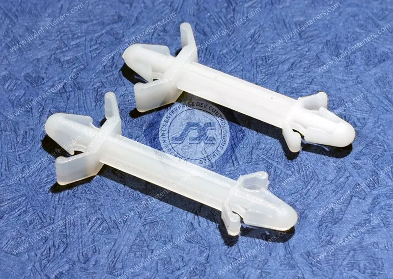
Snap-fit circuit board supports, locking PCB pillars, nylon PCB supports, and push-in circuit board mounts provide fast,
electrically insulating mechanical support between printed circuit boards and chassis structures without requiring
a conventional screw-and-nut fastening operation at every mounting point.
Product Specification
Snap-fit circuit board supports, locking PCB pillars, nylon PCB supports, and push-in circuit board mounts provide fast,
electrically insulating mechanical support between printed circuit boards and chassis structures without requiring a conventional screw-and-nut fastening operation at every mounting point.
These molded components are widely used in electronic equipment where engineers need to control PCB elevation,
maintain board-to-chassis clearance, reduce assembly operations, electrically isolate the board from conductive structures, and secure the PCB against movement during transportation and equipment operation.
Applications extend across industrial automation controllers, AI data center and high-performance computing infrastructure, power electronics,
power distribution equipment, semiconductor equipment, telecommunications infrastructure, medical electronics, robotics, instrumentation,
renewable-energy equipment, energy storage systems, appliances, and other electronic assemblies.
Unlike conventional threaded metal standoffs that may require a screw, washer, nut, or threaded chassis interface,
a snap-fit PCB support uses molded retention features to engage defined holes in the printed circuit board, chassis, panel, or mounting plate.
However, selecting a snap-fit PCB support by standoff height alone is not sufficient.
The complete mechanical interface should be evaluated as:
PCB Hole + PCB Thickness + Chassis Hole + Chassis Thickness + Standoff Height + Locking Geometry + Material + Environment
Juxin Fasteners supplies standard and custom snap-fit circuit board supports, locking PCB pillars, nylon PCB standoffs, spacers,
board supports, cable-management components, and drawing-based custom molded plastic fasteners for industrial OEM applications.
Engineering and sourcing review can begin from an existing manufacturer part number, OEM part number, 2D drawing, 3D CAD model, physical sample,
PCB layout, chassis dimensions, mounting-hole information, or required board-to-chassis spacing.
A snap-fit PCB support is a molded spacer or pillar that combines two functions:
Mechanical Spacing + Mechanical Retention
The central body establishes the required distance between the PCB and the chassis or between two circuit boards.
The end features provide the retention mechanism.
Depending on design, the component may incorporate:
snap-lock fingers;
arrowhead barbs;
push-in bases;
edge-locking features;
releasable latches;
threaded mounting features;
fixed spacer shoulders.
The result is a compact component capable of replacing multiple pieces of conventional mounting hardware in appropriate applications.
A sourcing request may initially state:
“We need a 12 mm PCB standoff.”
That does not establish interchangeability.
Two supports with the same nominal 12 mm standoff height may use completely different:
PCB mounting holes;
chassis mounting holes;
PCB thickness ranges;
panel thickness ranges;
locking geometries;
release methods;
base designs.
Therefore:
Same Standoff Height ≠ Same PCB Support
This distinction is critical for engineering selection and second-source qualification.
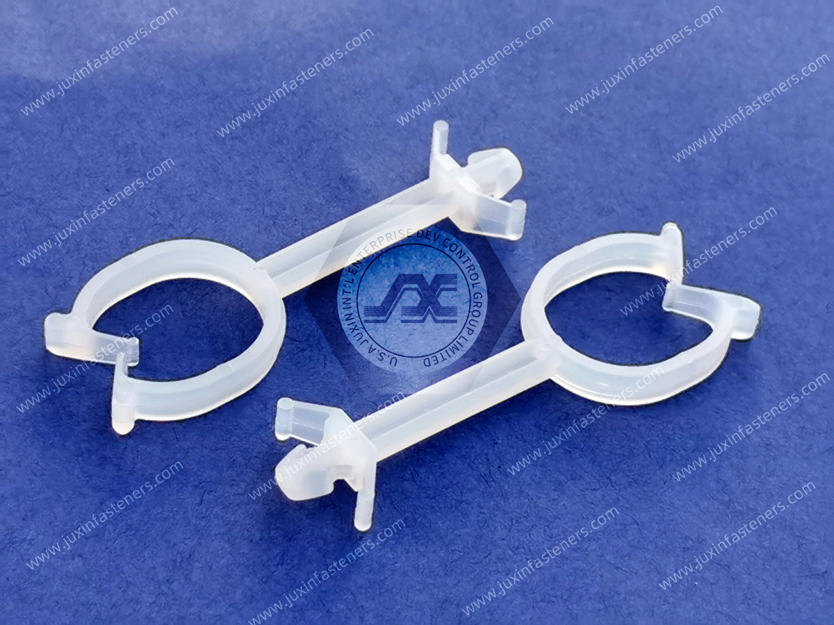
Both components establish controlled board spacing, but their assembly architectures are different.
Typically offers:
rapid push-in assembly;
reduced loose hardware;
no nut at the snap interface;
electrical insulation;
potential tool-free installation.
Typically offers:
positive threaded retention;
defined screw interface;
convenient controlled disassembly;
suitability for applications requiring threaded fastening.
Neither architecture is universally superior.
The correct choice depends on:
board load;
vibration;
service frequency;
assembly process;
available access;
retention requirements.
See our Nylon PCB Standoffs and Plastic Spacers and Standoffs solutions for threaded and non-snap mounting architectures.
Push-in / push-in supports use snap features at both mounting interfaces.
One end engages the chassis or base plate while the opposite end engages the PCB.
This configuration can reduce hardware count and assembly operations because no separate screw may be required at either interface.
However, both mounting interfaces must be dimensionally compatible.
The lower snap feature and upper snap feature should therefore be treated as two independent engineering interfaces.
Arrowhead or barbed mounting bases are designed to compress during insertion through a compatible chassis hole and then expand after passing through the panel.
The resulting shoulder or barb provides axial retention.
Performance depends on:
mounting-hole diameter;
panel thickness;
barb geometry;
material flexibility;
insertion direction.
An oversized hole may reduce retention.
An undersized hole may increase insertion force or damage the locking feature.
A snap-top support uses a locking feature to retain the PCB at the upper interface.
The snap head passes through the PCB mounting hole and then expands or engages above the board.
The support shoulder beneath the PCB controls the board elevation.
This architecture can be used with several different base designs, including:
snap-in base;
push-in base;
threaded base;
adhesive base in selected designs;
chassis-specific mounting feature.
Hybrid PCB supports combine a mechanically fastened base with a snap-lock upper interface.
The chassis side may be attached using a screw or other defined mounting method, while the PCB is retained by the molded snap feature.
This architecture can be useful where engineers want positive chassis retention while maintaining fast PCB installation.
It can also simplify PCB service where the board needs to be removed without removing the complete support from the chassis.
Some PCB mounting architectures retain the edge of the circuit board rather than using a conventional PCB mounting hole.
These designs solve a different mechanical problem and should not automatically be substituted for hole-mounted supports.
See our Edge-Locking PCB Supports solutions for board-edge retention applications.
There is no single universal PCB mounting-hole diameter for snap-fit circuit board supports.
Different support designs require different mounting holes.
Therefore, statements such as:
“PCB snap supports normally use a 4 mm hole”
should not be treated as a universal engineering rule.
The correct PCB hole diameter must be determined from:
component drawing;
manufacturer specification;
approved physical sample;
validated assembly.
For second-source projects:
Nominal Standoff Height + Approximate Appearance ≠ Dimensional Compatibility
The actual mounting interfaces must be checked.
The PCB mounting hole directly influences snap engagement.
If the hole is too small:
insertion force can increase;
locking fingers can overstress;
board damage can occur;
automated assembly may become inconsistent.
If the hole is too large:
lateral movement can increase;
locking engagement can decrease;
board vibration can increase;
pull-out resistance may be reduced.
The acceptable hole tolerance depends on the actual snap geometry.
PCB thickness is sometimes overlooked when replacing a snap-fit support.
However, many locking heads are designed around a defined board-thickness range.
If the board is too thin:
axial play may remain after locking;
the board may rattle;
vibration can increase.
If the board is too thick:
the snap head may not fully engage;
insertion force can rise;
the locking feature can remain partially compressed.
Therefore:
Correct PCB Hole + Incorrect PCB Thickness = Potentially Incorrect Assembly
Both dimensions must be qualified.
The lower mounting interface is equally important.
Depending on the support design, the chassis hole may be:
punched sheet metal;
drilled metal;
molded polymer;
another engineered mounting feature.
The hole diameter must be matched to the support base geometry.
Too small can create excessive insertion force.
Too large can reduce retention or introduce lateral movement.
A snap-in base may rely on the relationship between:
locking barb;
shoulder;
panel thickness.
If the chassis panel is too thick, the barb may not clear the rear surface sufficiently to lock.
If it is too thin, excessive axial clearance may remain.
For this reason:
Chassis Hole Diameter Alone ≠ Chassis Interface Compatibility
Panel thickness must also be checked.
The central spacer body establishes the nominal PCB elevation.
This dimension affects:
component clearance;
solder-joint clearance;
airflow;
electrical clearance;
connector alignment;
enclosure packaging.
A small change in standoff height can create interference elsewhere in a dense electronic assembly.
For replacement projects, nominal height should therefore be verified against the original part drawing or assembly.
A PCB is commonly mounted on multiple supports.
If support heights vary significantly, the board may be mechanically forced into a non-planar condition during installation.
Potential consequences include:
PCB bending;
local stress around mounting holes;
connector misalignment;
mechanical preload.
The mounting architecture should therefore be treated as a multi-point support system rather than as isolated individual fasteners.
More retention points do not automatically produce a better PCB assembly.
If all support locations tightly constrain the board while chassis dimensions and PCB dimensions vary independently, tolerance accumulation can preload the board.
Design engineers should consider:
number of supports;
hole tolerances;
support flexibility;
PCB dimensional tolerance;
chassis tolerance.
The objective is secure retention without unnecessary board stress.
PA66 is commonly used for molded electronic hardware because suitable grades can provide a useful combination of:
mechanical strength;
toughness;
fatigue resistance;
electrical insulation;
moldability;
snap-feature resilience.
However:
PA66 Is a Material Family, Not a Complete Product Specification
Actual properties depend on:
resin grade;
additives;
conditioning;
temperature;
geometry;
processing.
Project-specific material requirements should therefore be clearly identified.
Polyamide absorbs moisture from the surrounding environment.
This can change:
stiffness;
toughness;
dimensions;
flexibility;
snap engagement behavior.
Moisture conditioning may improve toughness in flexible snap features, but it can also affect dimensions and stiffness.
For precision electronic assemblies, engineers should evaluate the expected operating condition rather than relying only on dry-as-molded properties.
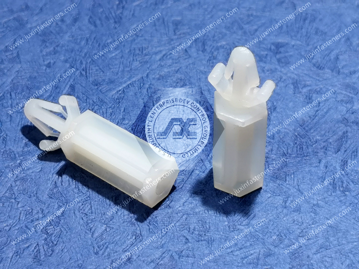
Electronic equipment may require a specified flammability classification.
Where UL 94 performance is required, the project should identify the required classification and applicable tested thickness.
It is important to distinguish:
PA66 ≠ UL 94 V-0
and
PA66 ≠ UL 94 V-2
The classification belongs to the specific resin formulation under defined test conditions and thicknesses.
Juxin Fasteners can evaluate project-specific flame-retardant material requirements when they are included in the drawing or RFQ.
High-density computing, power electronics, power conversion equipment, and industrial controllers can expose PCB hardware to elevated internal temperatures.
Where thermal exposure is significant, engineers should define:
normal operating temperature;
maximum continuous temperature;
short-term peak temperature;
thermal cycling profile.
A heat-stabilized material may be considered where required, but suitability must be evaluated against the complete application.
A nylon PCB support provides a non-metallic mechanical path between the circuit board and chassis at the mounting location.
This can help avoid direct metal-to-metal contact at that point.
However:
Plastic PCB Support ≠ Automatic Compliance with Electrical Clearance Requirements
The complete assembly must still consider:
conductor locations;
component leads;
solder joints;
chassis geometry;
voltage;
creepage paths;
clearance distances;
contamination environment.
Electrical safety requirements should be established by the equipment design.
For electrical equipment, engineers should distinguish:
Clearance = Shortest Distance Through Air
Creepage = Shortest Distance Along an Insulating Surface
Changing standoff height can affect clearance.
Changing support geometry and surface path can influence creepage.
A plastic support should therefore not be selected solely because it is “insulating.”
The complete electrical architecture must be evaluated according to the applicable equipment requirements.
Snap-fit support design involves an important engineering trade-off.
Low insertion force improves assembly ergonomics.
High retention force improves resistance to accidental board separation.
These objectives can conflict.
Conceptually:
Lower Insertion Force → Easier Assembly
Higher Retention Force → Stronger Mechanical Lock
The optimum design depends on the actual application.
A support intended for frequent field service may use a different retention strategy from one intended for permanent internal electronics.
Snap-fit PCB supports can be attractive for high-volume assembly because they reduce loose hardware and tool operations.
However, automated insertion requires consistent:
hole position;
hole diameter;
support orientation;
insertion force;
component feeding.
Excessive dimensional variation can cause:
incomplete seating;
bent locking fingers;
support misalignment;
production stoppages.
For automated assembly programs, sample validation should include the intended manufacturing process rather than only hand installation.
PCB supports in operating equipment can experience dynamic loading from:
cooling fans;
pumps;
motors;
compressors;
transportation;
machinery vibration.
The board itself has mass, and mounted components increase that mass.
Dynamic loading therefore acts through the PCB and into the support locations.
Support evaluation should consider:
Board Mass + Component Mass + Support Spacing + Vibration + Mounting Geometry
rather than the snap feature alone.
A lightly populated control PCB and a board carrying large transformers, inductors, heat sinks, or other heavy components do not impose the same mechanical load.
Where PCB mass is significant, design engineers may need:
additional support locations;
reinforced mounting;
threaded retention;
hybrid mounting architecture.
Snap-fit supports should be selected according to the actual board mass and dynamic environment.
PCB supports also control board deflection.
If supports are spaced too far apart, mechanical loads from:
connectors;
switches;
relays;
insertion forces;
cable connections;
can flex the PCB.
Therefore, the number and location of supports should be considered as part of the complete board mechanical design.
Standoff height affects more than board clearance.
It can also determine the position of:
I/O connectors;
card-edge connectors;
front-panel interfaces;
switches;
LEDs.
A seemingly minor height difference between an original support and a second-source component can therefore cause connector alignment problems.
This is another reason why second-source qualification cannot be based only on approximate physical appearance.
Some snap-fit PCB supports are designed for non-destructive release.
Others are intended primarily for permanent or semi-permanent assembly.
Before specifying a support, engineering teams should define:
expected service frequency;
required removal method;
allowable tools;
acceptable release force.
A high-retention snap support may be ideal for production but inconvenient for equipment requiring frequent field replacement of the PCB.
Snap-fit PCB supports are widely applicable to:
PLC assemblies;
industrial controllers;
I/O modules;
sensor interfaces;
machine-control electronics;
power-control assemblies.
Key considerations include vibration, electrical isolation, board replacement requirements, and production efficiency.
AI computing and high-performance computing infrastructure contain dense electronic assemblies with extensive:
power conversion;
monitoring electronics;
cooling controls;
rack management electronics;
auxiliary circuit boards.
Snap-fit PCB supports can provide efficient mounting in selected control, monitoring, power-distribution, and supporting electronic assemblies.
Design review should consider:
elevated internal temperature;
fan vibration;
serviceability;
board density;
electrical clearance.
Power conversion equipment can include:
inverters;
converters;
rectifiers;
UPS systems;
power supplies;
control boards.
These assemblies can combine elevated temperature, electrical isolation requirements, vibration, and high component mass.
Snap-fit support selection should therefore be coordinated with the complete mechanical and electrical architecture.
Semiconductor manufacturing equipment contains complex electronic control systems requiring precise component positioning and reliable serviceability.
Potential applications include:
controller boards;
sensor electronics;
interface boards;
auxiliary modules.
Dimensional repeatability and clean assembly architecture can be particularly important.
Modern network infrastructure requires compact, serviceable electronic assemblies.
Snap-fit PCB supports can be used in selected:
network equipment;
power modules;
monitoring electronics;
enclosure assemblies.
The material and geometry should be selected according to the actual thermal and mechanical environment rather than a generic telecommunications classification.
Inverters, energy storage systems, battery management electronics, monitoring systems,
and power conversion equipment can contain multiple PCBs requiring controlled spacing and electrical separation.
Relevant design factors can include:
temperature;
vibration;
electrical clearance;
serviceability;
material requirements.
Medical and laboratory equipment may require compact, clean internal electronic packaging.
Snap-fit supports can reduce loose hardware and simplify assembly, but project-specific requirements for:
materials;
cleaning;
chemicals;
temperature;
regulatory compliance;
must be defined by the equipment manufacturer.
Possible causes:
PCB hole too small;
wrong support series;
burr or contamination;
excessive snap-head dimension.
Possible causes:
PCB hole too large;
PCB too thick;
incompatible locking geometry;
incomplete insertion.
Possible causes:
board too thin for locking range;
oversized mounting hole;
incorrect support;
excessive axial clearance.
Possible causes:
chassis hole too large;
panel too thin;
incompatible base geometry;
excessive dynamic load.
Possible contributors:
undersized hole;
excessive insertion force;
unsuitable material condition;
low temperature;
misalignment.
Possible causes:
inconsistent support height;
tolerance stack-up;
over-constrained mounting pattern;
chassis distortion.
Possible causes:
incorrect standoff height;
tolerance stack-up;
wrong support shoulder geometry.
Possible contributors:
insufficient locking engagement;
oversized hole;
incorrect board thickness;
excessive board mass;
dynamic loading.
Failure analysis should evaluate:
Support + PCB + Chassis + Mounting Pattern + Board Mass + Environment
rather than the plastic support alone.
A procurement request may initially state:
“We need a 10 mm snap-in PCB support.”
That is not enough to determine interchangeability.
Two 10 mm supports can differ in:
PCB hole requirement;
PCB thickness range;
chassis hole requirement;
chassis thickness range;
locking-head geometry;
base geometry;
overall height;
release method;
material.
Therefore:
Same Standoff Height ≠ Same Mounting Interface ≠ Same PCB Support
For second-source qualification, both mounting interfaces must be verified.
For practical engineering and procurement review, Juxin Fasteners recommends verifying at least:
PCB Hole + PCB Thickness + Chassis Hole + Chassis Thickness + Standoff Height + Locking Geometry + Material
Where the support has additional features, the customer drawing should govern.
For demanding applications, also verify:
Board Mass + Vibration + Temperature + Electrical Requirements + Serviceability
This creates a much stronger basis for second-source qualification than standoff height alone.
Provide:
manufacturer;
manufacturer part number;
OEM part number;
2D drawing;
3D CAD model;
physical sample;
photographs.
Confirm:
PCB mounting-hole diameter;
PCB thickness;
PCB material where relevant;
mounting-hole tolerance.
Confirm:
chassis hole diameter;
chassis thickness;
chassis material;
mounting method.
Provide:
nominal board-to-chassis spacing;
tolerance;
connector alignment requirements;
component clearance requirements.
Specify:
board mass;
heavy components;
vibration;
shock;
support spacing;
service frequency.
Where applicable, specify:
voltage environment;
clearance requirements;
creepage requirements;
insulating material requirements.
Provide:
minimum temperature;
maximum temperature;
humidity;
chemical exposure;
other relevant operating conditions.
Specify where applicable:
PA66;
heat-stabilized material;
flame-retardant requirement;
other project-specific resin.
Check:
insertion effort;
full locking engagement;
board height;
chassis retention;
PCB flatness;
connector alignment;
release method.
Where required, evaluate:
pull-out retention;
vibration;
thermal cycling;
repeated removal;
long-term stability.
After approval, proceed to:
quotation;
material confirmation;
inspection requirements;
packaging;
lot traceability;
production planning.
Standard PCB supports cover many common electronic mounting requirements, but proprietary electronic equipment frequently requires drawing-specific geometry.
Custom requirements can include:
non-standard standoff height;
custom PCB mounting hole;
custom chassis hole;
special board-thickness range;
custom snap-head geometry;
custom base geometry;
offset support;
proprietary release feature;
dedicated polymer requirement.
Juxin Fasteners can support drawing-based custom PCB hardware through:
2D drawing review;
3D CAD review;
physical sample comparison;
dimensional analysis;
material evaluation;
DFM discussion;
tooling evaluation;
sample validation;
production sourcing.
See our Custom Molded Plastic Fasteners solutions for proprietary OEM electronic hardware.
For faster engineering review and quotation, provide as much of the following information as possible.
manufacturer;
manufacturer part number;
OEM part number;
drawing;
CAD model;
physical sample;
photographs.
PCB mounting-hole diameter;
PCB hole tolerance;
PCB thickness;
board dimensions;
approximate board mass;
heavy component locations where relevant.
chassis mounting-hole diameter;
panel thickness;
chassis material;
mounting orientation.
required standoff height;
overall length;
locking-head geometry;
base geometry;
other drawing dimensions.
insertion force requirement if specified;
retention requirement;
vibration;
shock;
support spacing;
repeated removal requirement.
electrical isolation requirements;
clearance requirements;
creepage requirements where applicable.
minimum temperature;
maximum temperature;
humidity;
chemical exposure;
other relevant conditions.
PA66;
heat-stabilized grade;
flame-retardant requirement where applicable;
other specified polymer.
sample quantity;
production quantity;
expected annual usage;
delivery schedule;
RoHS declaration;
REACH declaration;
material documentation;
lot traceability;
inspection requirements.
Providing both the PCB-side and chassis-side interface dimensions significantly improves second-source evaluation accuracy.
Related Juxin Fasteners product and engineering solutions include:
Edge-Locking PCB Supports for circuit-board edge retention;
Nylon PCB Standoffs for conventional board spacing and mounting;
Plastic Spacers and Standoffs for controlled component separation;
Nylon Machine Screws for non-metallic threaded PCB and enclosure assembly;
Cable Tie Mounts for internal wire-management anchoring;
Custom Molded Plastic Fasteners for proprietary electronic mounting hardware.
These components perform different functions within the electronic packaging architecture and should be selected according to the actual PCB,
chassis, spacing, electrical, environmental, assembly, and service requirements.
Juxin Fasteners supports electronics manufacturers, industrial automation companies, AI data center and HPC infrastructure suppliers,
power-electronics manufacturers, electrical equipment OEMs, semiconductor-equipment manufacturers, telecommunications infrastructure suppliers,
medical equipment companies, renewable-energy equipment manufacturers, energy-storage companies, robotics companies,
instrumentation manufacturers, contract manufacturers, procurement teams, and supplier-development organizations requiring standard or custom PCB hardware.
For snap-fit circuit board support projects, the sourcing pathway can begin with:
Existing Part / Drawing / Sample → PCB Interface Review → Chassis Interface Review → Standoff Height & Stack-Up Review
→ Mechanical / Electrical / Environmental Review → Material Selection → Candidate Support → Physical Sample → Assembly & Functional Validation → Second-Source Qualification → Production RFQ
This process can support:
new electronic product development;
PCB mounting optimization;
assembly-time reduction;
metal-to-plastic hardware conversion;
existing component replacement;
supplier consolidation;
second-source qualification;
obsolete component replacement;
custom PCB support development.
Send us your existing supplier part number, OEM part number, 2D drawing, 3D CAD model, physical sample, PCB hole diameter,
PCB thickness, chassis hole diameter, chassis thickness, required standoff height, board mass, temperature range,
vibration requirements, material specification, compliance requirements, and expected annual volume for technical review.
Email: info@juxinfasteners.com
Website: www.juxinfasteners.com
Product Packaging
Packaging Standard
At Juxin Fasteners, we apply standardized export packaging to ensure product protection, traceability, and compliance with international logistics requirements.
1. Standard Export Packaging
Unless otherwise specified, all products will be packed according to our factory standard export packaging, which includes:
Moisture-resistant inner protection
Poly bag or small box packing as required
Reinforced export cartons
Clear labeling with part number, specification, batch number, and quantity
Palletizing for sea or air shipment when necessary
Our standard packaging is designed to ensure safe transportation, efficient warehousing, and long-distance international shipping.
2. Customized Packaging Options
We also provide customized packaging solutions according to customer requirements, including but not limited to:
Private labeling
Customized barcodes
Specific carton dimensions
Retail packaging
Special pallet configuration
Customer-specific marking and identification
So that you know, customized packaging may involve additional costs and extended lead time depending on the complexity of the requirements.
3. Compliance & Quality Assurance
All packaging processes are controlled under our ISO 9001 quality management system to ensure consistency, traceability, and product integrity throughout the supply chain.
Product Pictures

Contact Us
Tel.:
+86 020 8621 0320
+86 020 3121 6067
E-mail:
Technical Support:
Navigation
SEND INQUIREY