Call Us
+86 136 6007 9809
Call Us
+86 136 6007 9809

Telecommunications infrastructure combines RF equipment, antenna systems, outdoor radio enclosures, optical fiber networks, network cabinets,
power distribution modules, and high-density electronic assemblies into equipment platforms that must operate reliably for extended service periods.
Product Specification
Telecommunications infrastructure combines RF equipment, antenna systems, outdoor radio enclosures, optical fiber networks, network cabinets,
power distribution modules, and high-density electronic assemblies into equipment platforms that must operate reliably for extended service periods.
For mechanical and electronics design engineers, the challenge is not simply choosing a plastic fastener instead of a metal one.
Each component must be selected according to its actual function: electrical isolation, RF-zone compatibility,
PCB spacing, cable retention, fiber routing, enclosure protection, vibration resistance, outdoor weatherability, or assembly efficiency.
Plastic fasteners and cable-management components can solve specific problems within telecom equipment where metallic hardware may be undesirable because of electrical conductivity,
galvanic interaction, surface damage, weight, or electromagnetic interaction near RF-sensitive zones.
However, polymer hardware should not be considered electromagnetically invisible, nor should plastic fasteners be treated as universal replacements for structural metallic fasteners.
A more reliable engineering selection path is:
Application Zone → RF Sensitivity → Mechanical Load → Electrical Function → Temperature → Outdoor Exposure → Material → Geometry → Validation
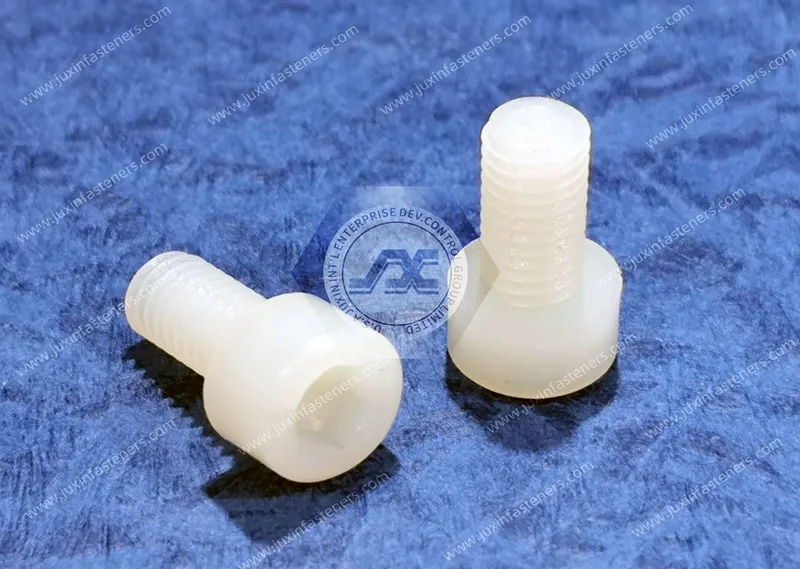
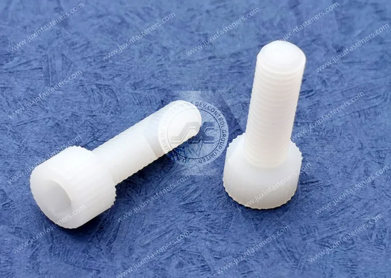
Juxin Fasteners supplies standard and drawing-specific plastic hardware for telecommunications equipment, including nylon machine screws, plastic nuts and washers,
insulating shoulder washers, PCB standoffs, snap-fit circuit board supports, cable clips, P-clips, cable tie mounts, snap bushings, strain relief grommets,
panel fasteners, and custom molded plastic components.
These components can support telecom equipment OEMs, antenna manufacturers, optical communications equipment suppliers, network hardware manufacturers,
enclosure manufacturers, and procurement teams developing qualified second sources.
Typical application zones include:
antenna systems;
antenna radomes;
outdoor radio equipment;
telecom cabinets;
power distribution modules;
PCB assemblies;
fiber distribution equipment;
network racks;
optical communications equipment;
edge network enclosures;
cable entry and strain-relief interfaces.
The engineering requirement changes significantly between these zones.
A fastener located close to an antenna radiating element may require dielectric characterization,
while a cable clip inside a network cabinet may be selected primarily for temperature resistance, flammability, geometry, vibration resistance, and harness retention.
Modern telecommunications antenna equipment integrates radiating elements, RF electronics, filtering components, control electronics, and supporting mechanical structures into compact assemblies.
Metal hardware placed in an RF-sensitive location can interact with electromagnetic fields.
Depending on:
operating frequency;
fastener dimensions;
component orientation;
electrical conductivity;
distance from the radiating element;
antenna geometry;
metallic components may influence the local electromagnetic environment.
Engineering polymers can therefore be useful for selected:
mounting screws;
spacers;
insulating washers;
PCB supports;
radome-related retainers;
non-structural positioning components.
But the correct engineering question is not:
“Is plastic RF transparent?”
The more useful question is:
“Does this specific polymer component provide acceptable dielectric and mechanical behavior in this specific RF location and operating frequency range?”
That distinction is important for telecom equipment design.
Polymers are electrically non-conductive, but they are not electromagnetically invisible.
Every polymer has dielectric properties that can influence an RF field.
Important parameters may include:
relative permittivity;
dissipation factor;
operating frequency;
moisture absorption;
filler content;
pigment system;
flame-retardant additives;
component geometry.
Therefore:
Non-Conductive ≠ Zero RF Interaction
An unfilled polymer, glass-filled grade, and flame-retardant formulation may have different dielectric behavior even when they belong to the same basic polymer family.
For antenna-adjacent components, RF engineers should validate the exact material grade rather than approving a component based only on the generic description “nylon.”
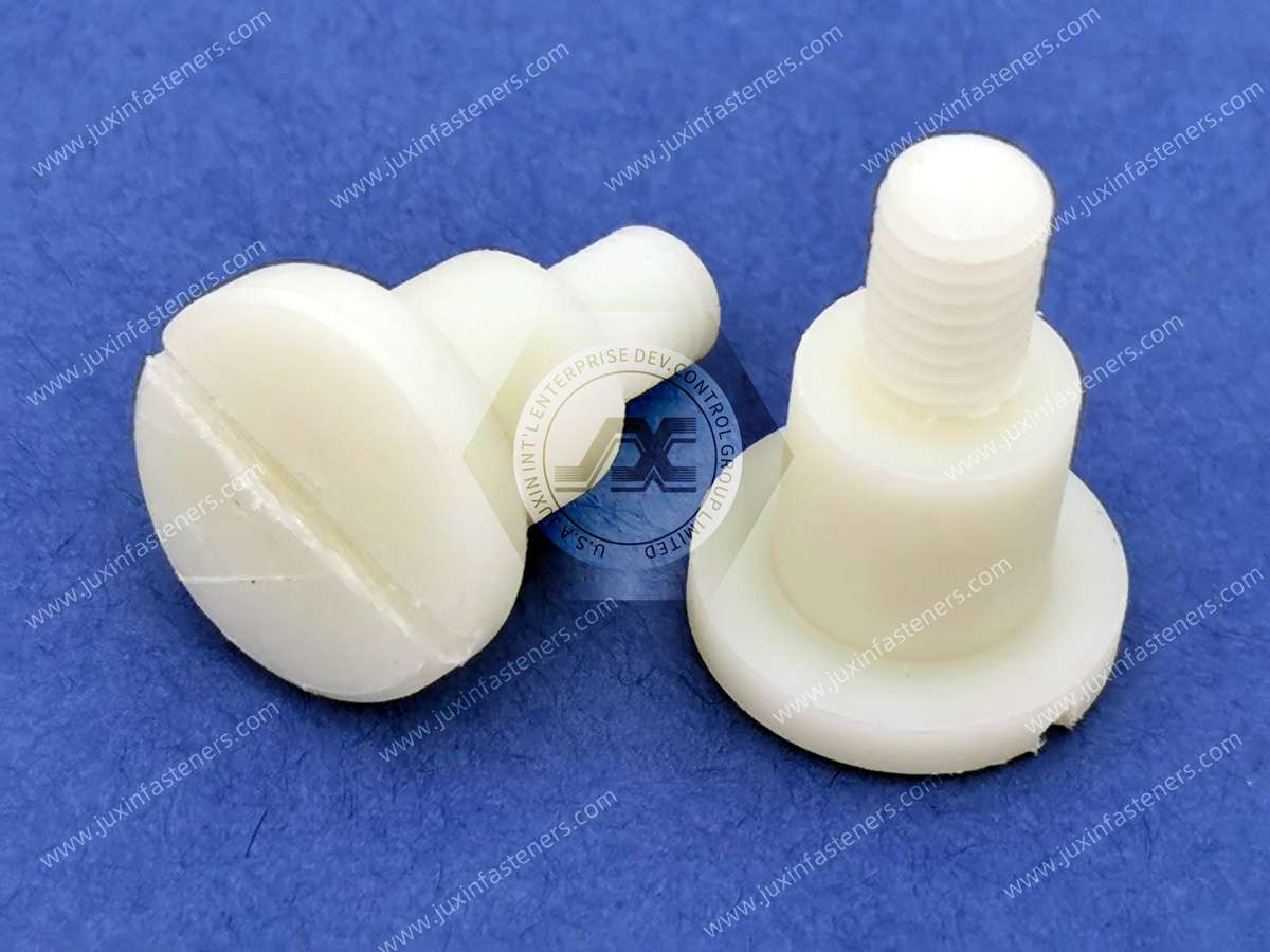
Consider three components commercially described as plastic fasteners:
Component A: Unfilled PA66
Component B: Glass-filled PA66
Component C: Flame-retardant PA66 with additives
Their mechanical and dielectric properties can differ.
Glass reinforcement can increase stiffness and dimensional stability but also changes the material system.
A flame-retardant formulation may satisfy an enclosure fire requirement while introducing additives that affect other material properties.
This creates an important selection principle:
RF Performance Must Be Evaluated at the Compound Level, Not Only the Polymer-Family Level
For RF-sensitive projects, the engineering team should therefore define the required dielectric characteristics or approve the proposed material grade.
Polyamides such as PA66 absorb moisture from the surrounding environment.
Moisture conditioning can influence:
dimensions;
stiffness;
toughness;
dielectric properties.
This can matter when a nylon fastener or spacer is positioned near a sensitive RF structure or used in a tight-tolerance mechanical interface.
The issue is not that PA66 is unsuitable.
The engineering issue is that the component should be evaluated in a condition representative of its actual service environment rather than relying only on dry-as-molded material properties.
For outdoor telecom equipment exposed to humidity and temperature cycling, this distinction becomes particularly relevant.
Radomes protect antenna systems from environmental exposure while allowing the antenna system to perform its intended RF function.
Hardware associated with radome assemblies may require:
low electrical conductivity;
controlled dielectric behavior;
UV resistance;
dimensional stability;
adequate mechanical retention;
environmental durability.
Potential plastic components include:
screws;
washers;
spacers;
panel retainers;
custom molded fastening components.
Hardware located within or near an RF-sensitive region should be reviewed as part of the complete antenna assembly because material, geometry, and location can all influence system performance.
Passive intermodulation, commonly referred to as PIM, can be an important consideration in RF telecommunications equipment.
Metal-to-metal interfaces, loose conductive contacts, surface contamination, unsuitable materials, and nonlinear junctions can contribute to PIM-related problems.
Using polymer hardware in an appropriate non-structural location may remove a conductive metal interface.
However:
Plastic Hardware ≠ Automatic PIM Compliance
The complete assembly may still require RF and PIM validation.
System performance can depend on:
connectors;
metallic contacts;
surface finishes;
assembly torque;
contamination;
grounding architecture;
adjacent conductive components.
Polymer fasteners should therefore be considered one possible engineering tool rather than a standalone PIM solution.
Outdoor telecommunications equipment may experience:
solar heating;
elevated internal electronics temperatures;
low winter temperatures;
humidity;
condensation;
wind-induced vibration;
UV exposure;
airborne contamination.
Plastic components may be used for:
internal cable routing;
PCB support;
insulating interfaces;
cable-entry protection;
control wiring;
removable panels;
secondary retention.
Material selection should be based on the actual environment surrounding the component.
A cable clip installed inside a protected cabinet may have very different requirements from a retainer exposed directly to sunlight, rain, and outdoor temperature cycling.
Telecom radio and network equipment can generate substantial heat.
Heat sinks and thermal interfaces may depend on:
controlled clamping pressure;
mechanical stability;
long-term preload;
thermal interface performance.
Plastic fasteners generally have lower stiffness and greater creep than metallic fasteners.
They should therefore not automatically replace structural heat-sink fastening hardware.
Plastic components may instead be appropriate around the thermal-management system for functions such as:
cable routing;
PCB isolation;
fan wiring;
airflow management;
low-load retention;
insulating interfaces.
This distinction prevents a common design mistake:
Electrical Isolation Requirement ≠ Permission to Replace Every Metal Fastener with Plastic
Telecommunications equipment contains dense electronic assemblies that require controlled spacing between circuit boards and chassis structures.
Potential hardware includes:
Nylon PCB Standoffs;
Snap-Fit Circuit Board Supports;
nylon machine screws;
plastic washers;
Insulating Shoulder Washers.
These components can provide:
board-to-chassis spacing;
electrical isolation;
tool-free assembly;
controlled mounting height;
reduced risk of unintended conductive contact.
Important dimensions include:
PCB hole diameter;
chassis hole diameter;
board thickness;
panel thickness;
standoff height;
locking geometry.
PCB standoff height should not be treated merely as a catalog dimension.
It can influence:
component clearance;
underside solder-joint clearance;
airflow;
creepage distance;
cable routing;
board deflection;
connector alignment.
For replacement PCB hardware, the engineering team should therefore verify:
Mounting Geometry + Standoff Height + Board Thickness + Hole Diameter + Electrical Clearance
rather than matching the standoff length alone.
Modern telecom networks depend heavily on high-density optical fiber routing.
Fiber requires different mechanical treatment from conventional electrical wiring.
Excessive:
bending;
compression;
twisting;
point loading;
can damage the cable or adversely affect optical performance.
Potential plastic hardware includes:
cable clips;
routing saddles;
adjustable clamps;
cable tie mounts;
custom routing components.
The purpose of fiber-management hardware is not simply to organize the enclosure.
It must retain and guide the fiber without creating harmful mechanical stress.
A cable clip can retain a fiber bundle securely while still forcing it through an unsuitable bend.
Therefore:
Retention Geometry + Routing Geometry = Fiber Management System
When selecting plastic fiber-routing hardware, engineers should evaluate:
cable outside diameter;
minimum bend radius specified by the cable manufacturer;
clip width;
routing direction;
bundle size;
installation path;
service access.
This becomes particularly important in high-density telecom cabinets and optical distribution equipment where routing space is limited.
Cable-management components should not be selected only according to maximum bundle diameter.
Fiber bundles can be mechanically sensitive.
An aggressive clamp may create excessive localized pressure.
A useful design principle is:
Secure the Route Without Crushing the Bundle
For high-density fiber applications, engineers may require retention geometry that allows controlled positioning without excessive compression.
Telecommunications equipment also contains:
DC power cables;
fan harnesses;
control wiring;
sensor wiring;
high-speed copper interconnects.
Potential hardware includes:
Nylon Cable Clips;
Heavy-Duty Nylon Cable Clamps & P-Clips;
adjustable cable clamps;
cable tie mounts;
strain-relief components.
Selection variables include:
bundle diameter;
bundle mass;
vibration;
orientation;
temperature;
installation space;
service requirements.
Cables frequently pass through punched or laser-cut cabinet openings.
Without edge protection, vibration, thermal movement, or field servicing can cause cable jackets to rub against sheet-metal edges.
Nylon Snap Bushings & Strain Relief Grommets can provide:
edge protection;
electrical isolation;
cable positioning;
strain management.
Critical dimensions include:
panel hole diameter;
panel thickness;
internal bore diameter;
cable outside diameter;
flange diameter.
For second-source qualification, both the plastic component and the host-panel geometry should be reviewed.
Exterior telecommunications equipment may remain installed for many years.
Polymer components exposed to direct sunlight can experience:
discoloration;
surface degradation;
embrittlement;
loss of mechanical properties.
UV-stabilized material grades may therefore be appropriate for exterior:
cable clips;
panel retainers;
antenna hardware;
routing components.
However, color alone does not establish long-term UV performance.
A black plastic component should not automatically be considered outdoor-qualified without reviewing the actual resin formulation and application requirements.
Outdoor telecom equipment can experience substantial temperature variation between:
daytime and nighttime;
summer and winter;
powered and unpowered conditions.
Plastic and metal have different coefficients of thermal expansion.
This can influence:
snap-fit engagement;
hole clearance;
clamp load;
dimensional alignment.
For tight-tolerance assemblies, designers should evaluate the full specified temperature range rather than room-temperature fit alone.
Telecom cabinets and electronic equipment may require plastic materials with specified flammability performance.
UL 94 classifications such as V-0 or V-2 apply to tested material specimens under defined conditions, including material thickness.
Therefore, engineers should avoid statements such as:
“This is PA66, therefore it is UL 94 V-0.”
Instead, qualification should identify:
exact resin grade;
documented flammability classification;
tested thickness;
application requirements.
For procurement teams, a generic resin description is not equivalent to documented material compliance.
This is particularly relevant to telecommunications hardware.
A flame-retardant additive package may improve fire performance while changing other characteristics of the polymer compound.
In an RF-sensitive zone, engineers may need to balance:
flammability;
dielectric behavior;
mechanical properties;
temperature resistance;
environmental durability.
This leads to an important engineering principle:
The Appropriate Polymer Depends on the Functional Zone
A material optimized for an indoor power cabinet is not automatically the correct material for hardware positioned near an antenna element.
| Application Zone | Primary Engineering Concern | Potential Plastic Hardware |
|---|---|---|
| Antenna / RF Zone | Dielectric Interaction | Polymer Screws / Spacers / Washers |
| Radome Assembly | RF + Weather Exposure | Plastic Fasteners / Custom Retainers |
| Radio Equipment Electronics | Isolation / Temperature | PCB Standoffs / Nylon Screws |
| PCB Assembly | Clearance / Isolation | Snap-Fit PCB Supports |
| Fiber Distribution | Bend Radius / Compression | Cable Clips / Routing Hardware |
| DC Power Cabling | Retention / Vibration | P-Clips / Cable Clamps |
| Cabinet Cable Entry | Edge Protection | Snap Bushings / Grommets |
| Outdoor Harness | UV / Weather / Vibration | Weather-Appropriate Cable Clips |
| Control Cabinet | Organization / Isolation | Tie Mounts / Clips / Standoffs |
| Proprietary Telecom Assembly | Custom Interface | Custom Molded Plastic Fasteners |
This matrix provides an initial selection path.
Final qualification should consider the exact equipment design, RF environment, material grade, temperature, mechanical loading, outdoor exposure, fire requirements, and customer specifications.
Possible causes:
different resin grade;
different filler content;
flame-retardant additives;
pigment changes;
moisture behavior.
Engineering lesson: Never approve antenna-adjacent plastic components based only on dimensions.
Possible causes:
incorrect clip position;
insufficient routing radius;
excessive bundle density;
inappropriate retention geometry.
Engineering lesson: Cable retention must preserve the required routing geometry.
Possible causes:
inadequate UV stabilization;
thermal aging;
unsuitable resin;
environmental exposure.
Possible causes:
incorrect PCB hole diameter;
incorrect chassis hole;
incorrect board thickness;
tolerance mismatch.
Possible causes:
oversized panel cutout;
incorrect panel thickness;
unsuitable locking geometry.
Possible causes:
creep;
stress relaxation;
excessive continuous load;
inappropriate resin grade.
These examples demonstrate why telecom second-source qualification should be based on functional requirements rather than visual similarity alone.
Telecom manufacturers may qualify alternative hardware suppliers because of:
supply-chain resilience;
cost optimization;
supplier consolidation;
obsolete components;
regional sourcing requirements;
capacity requirements;
new equipment platforms.
For polymer components, a second-source review should consider:
Geometry + Material Grade + RF Location + Mechanical Function + Electrical Function + Environment + Serviceability
Two components can share the same:
dimensions;
thread size;
head shape;
color;
while using different polymer compounds.
That difference may influence:
dielectric properties;
stiffness;
moisture absorption;
flammability;
temperature capability;
UV resistance;
snap behavior.
For telecom applications:
Dimensional Match ≠ Functional Match
This becomes particularly important for antenna-adjacent hardware, outdoor components, and electronic assemblies with defined safety or electrical requirements.
Provide where available:
OEM part number;
supplier part number;
2D drawing;
3D CAD model;
physical sample.
Examples:
antenna;
radome;
radio equipment;
PCB;
power cabinet;
fiber distribution;
cable entry;
network rack.
Provide:
thread size;
component dimensions;
PCB hole diameter;
panel hole diameter;
panel thickness;
cable OD;
bundle diameter;
standoff height.
For antenna-adjacent hardware, identify where relevant:
operating frequency range;
dielectric requirements;
filler restrictions;
PIM-related requirements;
approved material specifications.
Specify:
indoor or outdoor installation;
minimum temperature;
maximum local temperature;
humidity;
UV exposure;
vibration;
expected service life.
Examples include:
PA66;
POM;
PVDF;
PEEK;
flame-retardant grades;
UV-stabilized grades;
customer-approved resin.
Material availability and project suitability should be confirmed during engineering review.
Specify required documentation such as:
material data;
flammability information;
RoHS;
REACH;
lot traceability;
customer-specific documentation.
Verify:
dimensional fit;
insertion force;
retention;
cable routing;
PCB clearance;
assembly ergonomics.
Depending on the component and application, the OEM may evaluate:
RF performance;
PIM performance;
thermal cycling;
UV aging;
vibration;
insertion/extraction force;
flammability requirements;
environmental exposure.
After technical approval, procurement can define:
sample quantity;
prototype quantity;
production volume;
annual usage;
packaging;
documentation;
delivery schedule.
For faster technical review, provide the following information.
Equipment Type
antenna system;
outdoor radio equipment;
telecom cabinet;
fiber distribution equipment;
network rack;
edge network enclosure;
other telecommunications equipment.
Application Zone
RF zone;
radome;
PCB;
cable routing;
power section;
fiber management;
enclosure entry.
Existing Component
OEM part number;
supplier number;
drawing;
CAD model;
physical sample.
Dimensions
thread size;
overall dimensions;
mounting-hole diameter;
panel thickness;
PCB thickness;
standoff height;
cable OD;
bundle OD.
RF Requirements Where Applicable
operating frequency range;
dielectric requirements;
PIM considerations;
material restrictions.
Environmental Requirements
indoor/outdoor;
operating temperature;
humidity;
UV exposure;
vibration;
expected service life.
Material Requirements
PA66;
POM;
PVDF;
PEEK;
flame-retardant grade;
UV-stabilized grade;
customer-specified resin.
Compliance Requirements
RoHS;
REACH;
flammability documentation;
material documentation;
traceability;
customer-specific requirements.
Procurement Requirements
sample quantity;
prototype quantity;
production quantity;
estimated annual usage;
packaging;
target delivery schedule.
Related Juxin Fasteners product and engineering pages include:
Nylon Machine Screws for electrically isolated equipment fastening;
Nylon PCB Standoffs for controlled circuit-board spacing;
Snap-Fit Circuit Board Supports & Locking PCB Pillars for tool-free PCB mounting;
Insulating Shoulder Washers for axial and radial screw isolation;
Nylon Cable Clips for signal and control wiring;
Heavy-Duty Nylon Cable Clamps & P-Clips for larger cable bundles;
Cable Tie Mounts for organized telecom cabinet wiring;
Nylon Snap Bushings & Strain Relief Grommets for enclosure cable-entry protection;
Custom Molded Plastic Fasteners for proprietary antenna and enclosure interfaces.
The internal conversion path should be:
Telecom Application → RF / Electrical / Environmental Requirement → Engineering Requirement
→ Product Family → Drawing / Sample → Validation → Second-Source Qualification → RFQ
A telecommunications equipment platform can contain many small plastic components across antenna assemblies, radio equipment, power cabinets, optical distribution systems, and network enclosures.
Procurement teams can organize these components into functional sourcing families.
standoffs;
PCB supports;
nylon screws;
shoulder washers.
cable clips;
P-clips;
adjustable clamps;
cable tie mounts.
snap bushings;
strain relief grommets.
push rivets;
removable fasteners;
plastic screws.
selected polymer screws;
spacers;
washers;
drawing-specific components.
proprietary clips;
antenna retainers;
special spacers;
custom molded fasteners.
This functional-family approach can support:
BOM rationalization;
supplier consolidation;
common-part strategies;
second-source coverage;
qualification efficiency.
Standard catalog components do not solve every telecommunications hardware requirement.
Drawing-specific components may be required for:
proprietary antenna assemblies;
restricted RF zones;
unusual PCB spacing;
special cable-routing paths;
non-standard enclosure cutouts;
legacy equipment replacements.
Juxin Fasteners can support drawing-based sourcing for selected:
plastic screws;
nuts;
washers;
spacers;
standoffs;
PCB supports;
cable clips;
clamps;
bushings;
panel fasteners;
custom molded plastic components.
Project support can include:
drawing review;
CAD review;
physical sample comparison;
dimensional cross-referencing;
material discussion;
DFM review;
sample evaluation;
second-source development.
RF properties, flammability, outdoor performance, certifications, test requirements,
and customer-specific documentation should be confirmed for each individual project rather than assumed from the generic polymer family.
Juxin Fasteners supports telecommunications equipment manufacturers, telecom infrastructure suppliers, antenna manufacturers,
optical communications equipment companies, network hardware manufacturers, enclosure suppliers, procurement teams, and supplier-development engineers requiring standard or drawing-specific plastic hardware.
Our recommended sourcing workflow is:
Existing Part / Drawing / Sample → Application Zone → RF Sensitivity → Mechanical Function → Electrical Requirement
→ Temperature & Environment → Material Grade → Interface Geometry → Sample Validation → Customer Qualification → Production RFQ
This process can support:
new telecommunications equipment development;
RF-zone hardware review;
fiber-routing optimization;
obsolete-part replacement;
second-source qualification;
supplier consolidation;
common-platform component strategies;
custom plastic component development.
Send us your existing part number, 2D drawing, 3D CAD model, physical sample, application zone, thread or mounting dimensions,
cable or fiber dimensions, RF requirements where applicable, operating temperature, outdoor exposure, flammability requirements,
material specification, sample quantity, production quantity, and estimated annual usage for engineering review and RFQ evaluation.
Email: info@juxinfasteners.com
Website: www.juxinfasteners.com
Product Packaging
Packaging Standard
At Juxin Fasteners, we apply standardized export packaging to ensure product protection, traceability, and compliance with international logistics requirements.
1. Standard Export Packaging
Unless otherwise specified, all products will be packed according to our factory standard export packaging, which includes:
Moisture-resistant inner protection
Poly bag or small box packing as required
Reinforced export cartons
Clear labeling with part number, specification, batch number, and quantity
Palletizing for sea or air shipment when necessary
Our standard packaging is designed to ensure safe transportation, efficient warehousing, and long-distance international shipping.
2. Customized Packaging Options
We also provide customized packaging solutions according to customer requirements, including but not limited to:
Private labeling
Customized barcodes
Specific carton dimensions
Retail packaging
Special pallet configuration
Customer-specific marking and identification
So that you know, customized packaging may involve additional costs and extended lead time depending on the complexity of the requirements.
3. Compliance & Quality Assurance
All packaging processes are controlled under our ISO 9001 quality management system to ensure consistency, traceability, and product integrity throughout the supply chain.
Product Pictures
Contact Us
Tel.:
+86 020 8621 0320
+86 020 3121 6067
E-mail:
Technical Support:
Navigation
SEND INQUIREY