
Call Us
+86 136 6007 9809
Call Us
+86 136 6007 9809

Sep. 10, 2026
Automotive Rear Spoiler Fastening Components: Spoiler Bolts and Rear Spoiler Clips
Automotive rear spoiler assemblies require fastening components that match the mounting geometry, vehicle body structure,
spoiler materials and production assembly process.
Depending on the vehicle design, a fastening system may combine specially shaped metal Spoiler Bolts or Slide Bolts with plastic Rear Spoiler Clips or Retainer Clips.
Unlike general-purpose threaded fasteners, many automotive spoiler mounting components incorporate application-specific engagement features.
These may include shaped bolt heads, sliding mounting interfaces, locating surfaces, snap-fit retaining features or other geometry defined by the vehicle manufacturer.
JUXIN FASTENERS supplies customer-specific Spoiler Bolts, Slide Bolts and Rear Spoiler Clips according to approved engineering drawings, material requirements and application specifications.
Our focus is on OEM automotive component sourcing, custom fastening requirements and industrial production programs rather than universal aftermarket replacement parts.
This engineering guide examines the critical factors involved in selecting, specifying and sourcing automotive rear spoiler fastening components,
including dimensional compatibility, mechanical properties, material selection, assembly reliability, manufacturing quality and drawing-based RFQ requirements.
Understanding Automotive Rear Spoiler Fastening Systems
A rear spoiler fastening system provides the mechanical connection between a spoiler assembly and its supporting vehicle structure.
Depending on the design, the mounting interface may involve a trunk lid, tailgate, body panel, reinforcement bracket or another structural component.
The fastening arrangement may include:
Specialized metal Spoiler Bolts
Slide Bolts with shaped mounting heads
Plastic Rear Spoiler Clips
Plastic Retainer Clips
Mating threaded components
Locating and positioning features
Customer-specified sealing or isolation elements
Not every spoiler assembly requires all these components.
The exact arrangement is determined by the vehicle design, mating geometry, installation process and functional requirements.
For engineering purposes, it is important to distinguish between components that provide threaded clamping,
components that establish position and components that provide snap-fit retention.
A metal spoiler bolt and a plastic spoiler clip may operate together, but their mechanical functions are not necessarily interchangeable.
The complete fastening interface must be evaluated rather than selecting individual parts solely by their nominal dimensions.
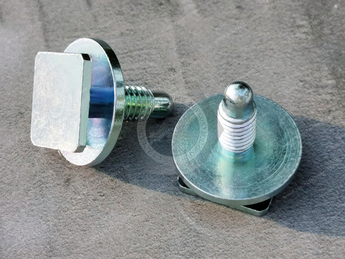
Spoiler Bolts and Slide Bolts: Specialized Metal Fastening Components
A Spoiler Bolt is a threaded metal fastening component used in a rear spoiler mounting assembly.
In certain automotive designs, the bolt incorporates a specially shaped head intended to engage with a slot, channel, bracket or other mounting feature.
The term Slide Bolt is commonly used for designs in which the bolt head can enter or move along a compatible mounting interface before final positioning and tightening.
These terms describe product application and function. They do not establish a universal dimensional standard.
A conventional bolt and a specialized slide bolt may share the same nominal thread size while having substantially different head geometry and installation requirements.
For OEM sourcing, the correct component must therefore be identified by its approved engineering drawing and mating-interface specifications.
Specialized Head Geometry and Double-Level Slide Bolt Designs
Some spoiler slide bolts use a stepped or multi-level head configuration, including designs with two distinct head levels or bearing surfaces.
Depending on the customer design, the upper and lower head features may interact with different sections of a mounting channel or bracket.
This type of geometry can be used to establish positioning and engagement within a defined mounting interface.
However, the function of each head level must be confirmed from the actual engineering drawing.
Critical design characteristics may include:
Upper head width and length
Lower head width and length
Head thickness and step height
Distance between functional bearing surfaces
Head-to-shank transition geometry
Threaded shank diameter
Overall and functional length
Edge radii and chamfers
Coating thickness on engagement surfaces
Dimensional tolerances of the mating channel
A double-level head should not automatically be assumed to provide a specific load capacity or anti-rotation performance.
Those characteristics depend on the contact geometry, material properties and complete mounting assembly.
For customer-specific spoiler bolts, both the bolt drawing and the mating-slot drawing are valuable for evaluating functional compatibility.
Representative JUXIN Spoiler Bolt Specifications
The existing JUXIN product information identifies the following representative configurations.
| Specification | Product Information |
|---|---|
| Product terminology | Spoiler Bolt, Slide Bolt, Spoiler Assembly Bolt |
| Representative thread sizes | M5 and M6 |
| Representative M6 configurations | M6 × 14 and M6 × 20 |
| Steel property class options | 8.8 and 10.9, subject to customer requirements |
| Surface finish options | Color Zinc, Zinc-Nickel Alloy and Black Zinc |
| Optional locking feature | Pre-applied thread-locking patch on specified configurations |
| Head geometry | Customer-specific shaped or stepped mounting head |
| Manufacturing basis | Approved engineering drawings and technical specifications |
These specifications represent documented product configurations and options, not a universal product catalogue.
Exact dimensions, material grades, thread details, surface finishes and manufacturing requirements must be confirmed for each customer project.
How Slide Bolts Engage with Automotive Spoiler Mounting Channels
For a mounting system using a compatible slot or channel, the assembly process may follow four functional stages:
Slide → Position → Engage → Tighten
Slide
The specially shaped bolt head enters the designated mounting opening.
The entrance geometry must accommodate the relevant head dimensions, including dimensional tolerances and surface coating.
Position
The bolt moves into the specified mounting location.
The available movement depends on the channel length, mounting geometry and surrounding components.
Engage
The shaped head interacts with the mating surfaces.
Depending on the design, the geometry may provide positioning, constrain movement or resist rotation during tightening.
Tighten
The threaded connection is tightened according to the customer-approved joint and assembly requirements.
The final tightening procedure must consider the mating material, thread engagement, clamping arrangement and specified assembly conditions.
This sequence is a functional explanation rather than a universal installation instruction.
Actual installation must follow the applicable vehicle or component assembly specification.
Engineering Design of Bolt Heads and Mounting Slots
The bolt head and mating slot form a functional interface.
Their dimensional relationship is often more important to installation compatibility than the nominal thread diameter alone.
Head-to-Slot Clearance
The bolt head must enter the mounting opening and engage the intended surfaces.
Insufficient clearance can cause interference, assembly damage or incomplete installation.
Excessive clearance may permit unwanted movement or reduce the effectiveness of locating and anti-rotation features.
The appropriate clearance must be determined from the customer design and tolerance requirements.
Head Thickness and Channel Depth
Head thickness and channel depth influence whether the bolt can enter, move and remain correctly positioned.
For stepped or double-level heads, the relative dimensions of the different head levels may also affect engagement.
Anti-Rotation Geometry
Certain shaped bolt heads are intended to resist rotation during tightening.
The actual resistance depends on contact area, engagement depth, mating material and the tightening conditions.
A head that physically fits inside a channel is not necessarily capable of resisting the required installation torque.
Contact and Bearing Surfaces
The mounting interface should be evaluated for local contact conditions.
Concentrated contact loads may damage a thin bracket, deform a mounting feature or compromise the intended fastening function.
The suitability of the interface depends on the actual material and geometry.
Dimensional Tolerance Stack-Up
The final assembly must account for dimensional variation across the bolt, mounting channel, bracket and related components.
A component may satisfy its individual drawing while the complete assembly experiences interference or excessive clearance if the combined tolerances are not evaluated.
For OEM projects, the critical functional dimensions should be identified during design review and included in the agreed inspection requirements.
Metric Threads and Dimensional Compatibility
JUXIN's representative spoiler bolt configurations include M5 and M6 metric threads.
Metric screw thread specifications should identify the nominal diameter, pitch and applicable tolerance class.
Relevant international standards include ISO 261 for general-purpose metric thread selection and the applicable ISO 965 series for thread tolerances.
The mating threaded component must use a compatible thread specification.
Nominal thread diameter alone does not establish compatibility.
For reference:
| Metric dimension | Approximate inch conversion |
|---|---|
| M5 nominal diameter, 5 mm | 0.197 in |
| M6 nominal diameter, 6 mm | 0.236 in |
| 14 mm | 0.551 in |
| 20 mm | 0.787 in |
These values are dimensional conversions only.
Metric threads and UNC, UNF, BSW or BSF thread systems are not directly interchangeable merely because their nominal diameters are similar.
In addition, a designation such as M6 × 20 does not independently define the bolt-head geometry, actual thread pitch, threaded length or the reference points used for the length dimension.
Those details must be confirmed against the approved drawing.
Steel Property Classes 8.8 and 10.9
JUXIN's existing product information identifies property class 8.8 and 10.9 options for applicable spoiler bolt configurations.
ISO 898-1 specifies mechanical and physical properties for certain carbon-steel and alloy-steel bolts, screws and studs within its defined scope.
Property classes 8.8 and 10.9 describe standardized mechanical property classifications. They are not hardness grades.
A critical engineering consideration is that specially shaped bolt heads may influence the loadability of the finished fastener.
A bolt with material properties corresponding to a particular property class does not automatically demonstrate that its nonstandard head geometry can
withstand every proof-load or tensile-load requirement applicable to a conventional full-loadability bolt.
Where specialized head geometry affects mechanical performance, the required finished-part testing and acceptance criteria should be agreed with the customer.
ISO 898-1 does not independently establish corrosion resistance, fatigue performance, tightening torque or complete-joint durability.
These requirements must be addressed separately where relevant to the application.
Surface Finishes and Corrosion Protection
The existing JUXIN spoiler bolt information identifies the following finish options:
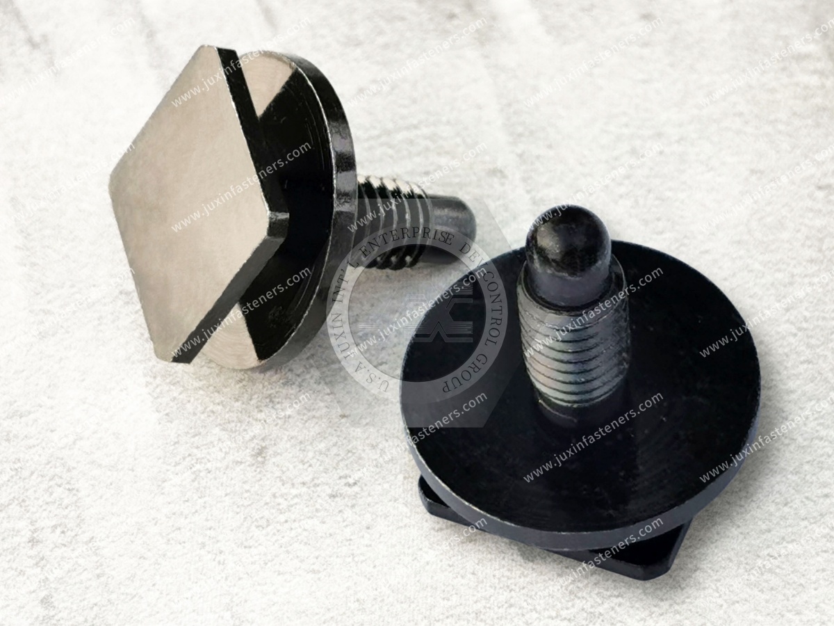
Color Zinc
Zinc-Nickel Alloy
Black Zinc
Surface finish selection should be based on the customer specification, base material, installation environment and functional requirements.
For exterior automotive applications, relevant considerations may include:
Moisture exposure
Road contaminants
Contact with dissimilar materials
Surface coating compatibility
Dimensional effects of coating thickness
Corrosion resistance requirements
Appearance requirements where applicable
Manufacturing process risks
The corrosion performance of a finished component depends on the complete coating system, not simply the general name of the finish.
Where specified, ISO 9227 provides salt spray test methods.
However, ISO 9227 does not establish a universal corrosion-resistance requirement or mandatory salt spray duration for all automotive spoiler bolts.
Acceptance criteria must be defined by the customer or applicable product specification.
For higher-strength steel fasteners, the selected coating process should also be reviewed for hydrogen embrittlement risks where relevant.
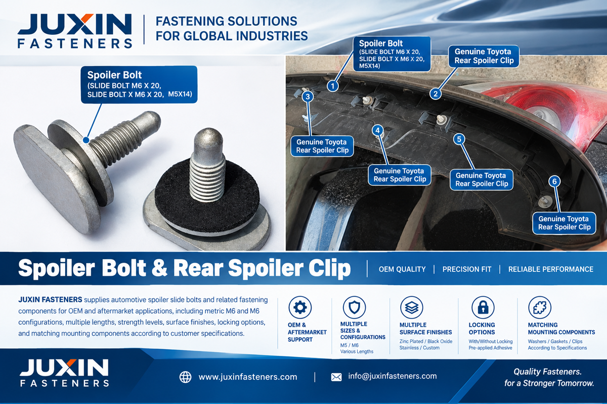
Thread-Locking Patches and Joint Security
Certain customer-specific spoiler bolt configurations may incorporate a pre-applied thread-locking patch.
This feature may be considered where the joint design requires additional resistance to loosening or a specified prevailing-torque characteristic.
Its performance depends on:
Thread dimensions and tolerances
Mating thread material
Surface coating
Patch material and application location
Assembly temperature
Installation procedure
Required tightening and prevailing torque
Customer-defined service conditions
A pre-applied locking patch is not a substitute for appropriate joint design.
The specified tightening torque and functional acceptance criteria must be established for the actual assembly.
Rear Spoiler Clips and Plastic Retaining Components
Automotive rear spoiler assemblies may also incorporate specialized plastic clips or retainers.
Common industry terminology includes:
Rear Spoiler Clip
Automotive Rear Spoiler Clip
Rear Spoiler Retainer Clip
Spoiler Clip
Rear Spoiler Retainer
Depending on the design, a plastic rear spoiler clip may perform one or more functions:
Positioning a spoiler component
Retaining a trim or mounting feature
Providing a snap-fit connection
Maintaining spacing between components
Supporting an assembly interface
The actual function is determined by the component geometry, mating surfaces, material and installation conditions.
JUXIN FASTENERS supplies customer-specific Rear Spoiler Clips according to approved drawings and technical requirements.
The components should not be treated as universal replacement clips merely because their external appearance is similar.
Plastic Rear Spoiler Clip Design and Material Selection
Plastic clip performance depends on the interaction between material behavior and component geometry.
The selection process should consider the following engineering factors.
Mating Hole and Panel Thickness
The clip geometry must correspond with the intended mounting hole, slot or panel feature.
Relevant dimensions may include hole width, hole length, panel thickness, retention-arm geometry and available engagement depth.
The permitted tolerances should be evaluated together.
Insertion Force
Insertion force affects assembly ergonomics, installation equipment and the risk of component damage.
A clip requiring excessive installation force may be difficult to seat consistently or may damage the mating panel.
Insufficient insertion resistance, however, does not by itself prove inadequate retention. The full engagement geometry must be evaluated.
Retention and Extraction Force
Retention force is a separate functional requirement from insertion force.
It depends on the clip design, mating geometry, material properties and environmental conditions.
The required force should be established from the application and validated using the agreed test method.
Polymer Material Requirements
Material selection should consider the actual automotive service environment.
Relevant factors may include:
Stiffness and flexibility
Resistance to deformation
Creep under sustained loading
Temperature-dependent mechanical behavior
Moisture absorption
Chemical compatibility
Environmental aging
Dimensional stability
No particular polymer grade should be assumed suitable without considering the application requirements.
Snap-Fit Geometry
Snap-fit retention features must allow installation while providing the required engagement.
Critical geometry may include retaining arms, hooks, flexible sections, contact surfaces and local transitions.
Sharp transitions, excessive strain or unfavorable contact geometry may increase the risk of cracking or permanent deformation.
Assembly and Serviceability
Some plastic clips are intended for a single installation. Other designs may need to accommodate specified removal and reinstallation procedures.
Repeated engagement should not be assumed acceptable without suitable validation.
International Engineering Standards and Technical References
Automotive spoiler fastening components may involve several standards and engineering references.
However, there is no single universal international product standard established here that defines every specialized Spoiler Bolt, Slide Bolt and Rear Spoiler Clip.
The applicable requirements depend on the actual component.
| Standard or reference | Relevant engineering scope |
|---|---|
| ISO 898-1 | Mechanical and physical properties of applicable carbon-steel and alloy-steel threaded fasteners |
| ISO 261 | General-purpose ISO metric screw thread selection |
| ISO 965 series | Applicable ISO metric thread tolerances |
| ISO 9227 | Salt spray corrosion test methods |
| SAE USCAR47 | Assembly-force guidance for manually seated retention devices within its defined scope |
| OEM engineering specifications | Product-specific geometry, materials, assembly, functional testing and acceptance requirements |
SAE USCAR47 addresses certain manually seated clips and similar retention devices.
It does not apply universally to every spoiler clip and does not establish extraction or retention-force requirements.
Standards developed for automotive wire-harness retainers should not automatically be applied to spoiler mounting clips.
For custom components, customer-approved engineering specifications remain essential.
Engineering Comparison: Metal Spoiler Bolts and Plastic Rear Spoiler Clips
| Engineering consideration | Spoiler Bolt / Slide Bolt | Rear Spoiler Clip |
|---|---|---|
| Primary function | Threaded fastening and mounting engagement | Locating, retaining or snap-fit engagement |
| Critical geometry | Head, thread, length and mating slot | Retention features and mating panel |
| Material considerations | Steel properties and surface finish | Polymer properties and environmental behavior |
| Installation | Positioning and tightening | Insertion and engagement |
| Functional verification | Thread, head engagement and joint requirements | Insertion, retention and deformation |
| Potential failure modes | Rotation, interference, loosening or local deformation | Breakage, incomplete seating or loss of retention |
| RFQ basis | Bolt drawing and mating-interface information | Clip drawing and mounting-panel information |
The correct selection depends on the complete assembly design.
Common Fastening Problems and Failure Prevention
Slide Bolt Cannot Enter the Mounting Slot
Possible causes include oversized head geometry, undersized slot dimensions, coating build-up or interference with adjacent components.
Engineering response: Verify the functional dimensions, tolerance limits and mating-interface geometry.
Bolt Head Rotates During Tightening
Possible causes include inadequate anti-rotation engagement, excessive clearance or unsuitable contact geometry.
Engineering response: Evaluate the actual head-to-slot engagement and customer-defined tightening conditions.
Bolt Fits but Does Not Position Correctly
Possible causes include incorrect step height, channel geometry, functional length or assembly sequence.
Engineering response: Review the complete mounting interface, including all relevant locating and bearing surfaces.
Spoiler Mounting Position Varies
Possible causes include accumulated tolerances, inconsistent locating features or assembly variation.
Engineering response: Establish the intended locating scheme and analyze dimensional variation across the assembly.
Plastic Clip Breaks During Installation
Possible causes include excessive insertion force, unfavorable snap-fit geometry, material limitations or misalignment.
Engineering response: Evaluate insertion conditions, critical geometry and material behavior.
Plastic Clip Loses Retention
Possible causes include incomplete engagement, incompatible mating dimensions, deformation, environmental effects or unsuitable retention geometry.
Engineering response: Verify the installed condition and customer-specified retention requirements.
Fastened Joint Becomes Loose
Possible causes include inadequate preload, joint settlement, unsuitable locking provisions or changes in mating-component behavior.
Engineering response: Review the joint design and perform the required functional validation.
These are general engineering failure mechanisms. The actual cause of a specific assembly problem must be established through inspection and testing.
Production Engineering and Assembly-Line Reliability
For OEM production programs, the fastening component must support a repeatable assembly process.
Production managers and manufacturing engineers may need to evaluate:
Component orientation during installation
Compatibility with manual or automated assembly
Consistency of slide-bolt engagement
Accessibility of tightening tools
Clip insertion repeatability
Risk of damaging painted or visible surfaces
Prevention of incomplete seating
Component identification and mix-up prevention
Critical dimension consistency
Packaging protection for functional features
Inspection accessibility
Rework and service requirements
A fastening design that functions in a prototype may still require further evaluation before high-volume production.
For example, a slide bolt may engage correctly under ideal conditions but become difficult to install when manufacturing tolerances across several mating components are considered.
Similarly, a plastic clip may demonstrate acceptable initial retention while requiring additional validation for the intended environmental and service conditions.
Production feasibility should therefore be evaluated alongside functional design.
Quality Inspection and OEM Validation Requirements
Quality requirements should be established according to the approved component drawing and the intended application.
Spoiler Bolt Inspection Considerations
Relevant checks may include:
Thread diameter and pitch
Thread tolerance
Overall and functional length
Upper and lower head geometry
Head thickness and step height
Critical bearing surfaces
Material specification
Applicable mechanical properties
Surface finish
Coating thickness where specified
Locking patch characteristics where applicable
Functional fit with the mating interface
Where the customer requires mechanical or assembly testing, the method and acceptance criteria must be agreed.
Rear Spoiler Clip Inspection Considerations
Relevant checks may include:
Critical external dimensions
Retention-arm geometry
Material specification
Mating-hole compatibility
Panel thickness compatibility
Insertion force
Retention or extraction force
Installation damage
Environmental conditioning
Functional engagement after specified service operations
The required sampling plan, measurement methods, inspection reports and acceptance criteria depend on the individual customer project.
No particular certification, automotive approval or validation result is implied unless it is explicitly established for the relevant supply program.
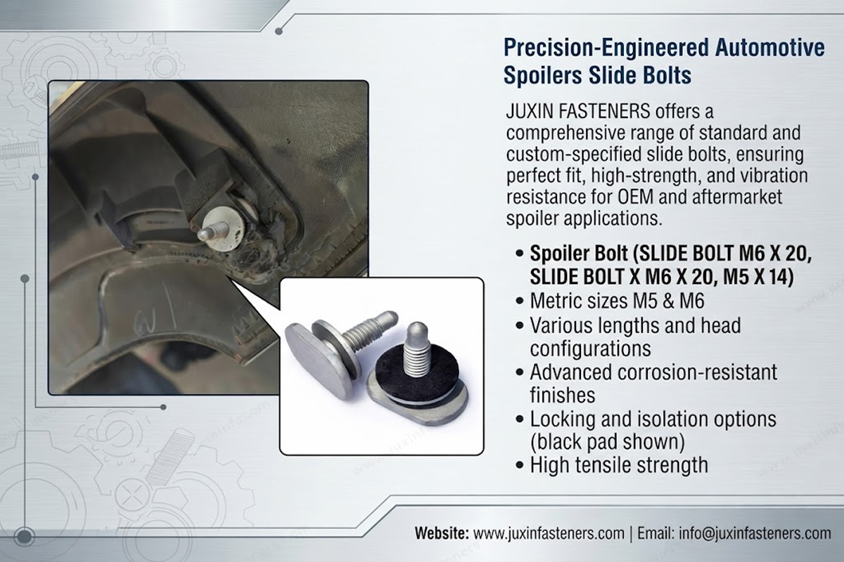
OEM Supplier Development and Drawing-Based Manufacturing
JUXIN FASTENERS supplies custom automotive rear spoiler fastening components according to customer-approved designs.
For OEM and Tier-1/Tier-2 sourcing projects, the quality of the technical specification is essential to successful supplier evaluation.
A nominal bolt size or product photograph may be insufficient to establish manufacturing feasibility or quotation accuracy.
For a specialized slide bolt, the customer should provide the bolt drawing and relevant information about the mating channel.
For a plastic rear spoiler clip, the clip drawing and mating-panel information help define the intended engagement and retention function.
Engineering and procurement teams should align the following information before requesting production quotations:
Approved product geometry
Material requirements
Functional dimensions and tolerances
Surface finish or polymer requirements
Assembly conditions
Applicable international standards
Customer-specific testing
Inspection requirements
Expected production quantities
Packaging requirements
Project schedule
This reduces the risk of quoting a component that matches the nominal product description but not the actual assembly requirements.
RFQ Checklist for Custom Spoiler Bolts and Slide Bolts
For accurate technical evaluation and quotation, please provide:
2D engineering drawings
Available 3D CAD files
Thread size, pitch and tolerance
Overall and functional length
Head geometry and critical dimensions
Upper and lower head dimensions where applicable
Mating slot or mounting-channel information
Material and required property class
Surface finish and coating requirements
Thread-locking requirements where applicable
Assembly and tightening requirements
Inspection and validation requirements
Prototype and production quantities
Estimated annual purchasing volume
Packaging and target delivery schedule
RFQ Checklist for Custom Rear Spoiler Clips
Please provide:
2D component drawings
Available 3D CAD models
Mating-hole or slot dimensions
Panel thickness and tolerances
Required polymer material or material properties
Installation direction
Insertion force requirements
Retention or extraction force requirements
Temperature and environmental requirements
Service removal and reinstallation requirements
Critical dimensional inspection requirements
Functional testing requirements
Expected production and annual quantities
Packaging requirements
Project delivery schedule
Where the fastening system is still under development, mating-component drawings and assembly information can help clarify the technical requirements.
Frequently Asked Questions
What is an Automotive Spoiler Bolt?
An Automotive Spoiler Bolt is a threaded metal fastener used within a vehicle spoiler mounting assembly.
Depending on the design, it may incorporate a specialized head for engagement with a mounting bracket, slot or channel.
What is a Spoiler Slide Bolt?
A Spoiler Slide Bolt is a fastener designed to enter or move along a compatible mounting interface before final positioning or tightening.
Its head geometry and engagement characteristics are defined by the application.
Are Spoiler Bolts and Slide Bolts the same product?
The terms can overlap in certain applications, but they are not universally interchangeable.
Spoiler Bolt describes the application, while Slide Bolt describes a particular mounting function.
What is a double-head or stepped Spoiler Bolt?
It is a specialized bolt configuration incorporating distinct head levels or stepped engagement surfaces.
The dimensions and function of each level depend on the approved customer design.
What sizes of Spoiler Bolts does JUXIN supply?
JUXIN's existing product information identifies representative M5 and M6 configurations, including M6 × 14 and M6 × 20.
Exact specifications and availability must be confirmed for the project.
Can a standard M6 bolt replace an M6 Spoiler Bolt?
Not necessarily. A matching thread diameter does not establish compatibility.
The head geometry, length, mating interface, material and installation requirements must also match.
What do property classes 8.8 and 10.9 mean?
They are standardized mechanical property classifications for applicable steel fasteners.
They are not hardness grades, and specialized bolt geometry may require additional finished-part verification.
Which surface finishes are available for JUXIN Spoiler Bolts?
The existing product information identifies Color Zinc, Zinc-Nickel Alloy and Black Zinc options, subject to customer specifications and technical confirmation.
What is the function of a Rear Spoiler Clip?
A Rear Spoiler Clip may locate, retain, space or connect components within a rear spoiler assembly.
Its function depends on the clip geometry and mating structure.
How are plastic Rear Spoiler Clips selected?
Selection should consider the component geometry, mating-panel dimensions, polymer properties, installation method, insertion force, retention requirements and service environment.
Are Rear Spoiler Clips universal across vehicle models?
No. Clips with similar appearances may have different dimensions, materials, engagement features and retention characteristics.
Compatibility must be established from the actual component specification.
Which international standards apply to these components?
Relevant standards may include ISO 898-1 for applicable steel fastener mechanical properties, ISO 261 and ISO 965 for metric threads, and ISO 9227 for specified corrosion testing.
SAE USCAR47 may be relevant to certain manually seated clips within its defined scope.
OEM-specific requirements must be evaluated separately.
Can JUXIN manufacture custom Spoiler Bolts and Rear Spoiler Clips from drawings?
Yes. JUXIN FASTENERS supplies customer-specific metal spoiler bolts and plastic rear spoiler clips according to approved engineering drawings and application requirements, subject to technical review.
What information is required for an OEM quotation?
Customers should provide 2D drawings, available 3D CAD files, materials, critical dimensions, tolerances, assembly requirements, quality specifications, expected quantities and target delivery requirements.
Request a Custom Automotive Spoiler Fastener RFQ
JUXIN FASTENERS supports OEM sourcing projects for custom Spoiler Bolts, Slide Bolts and Rear Spoiler Clips.
If your engineering, manufacturing, supplier development or procurement team requires customer-specific automotive rear spoiler mounting components,
please submit your engineering drawings and technical requirements for evaluation.
We welcome inquiries involving new component development, drawing-based custom parts and industrial production sourcing.
Company: JUXIN FASTENERS
Email: info@juxinfasteners.com
Website: https://www.juxinfasteners.com/
JUXIN FASTENERS — Drawing-Based Custom Automotive Fastening Components for Global OEM Procurement.
Contact Us
Tel.:
+86 020 8621 0320
+86 020 3121 6067
E-mail:
Technical Support:
Navigation
SEND INQUIREY



