
Call Us
+86 136 6007 9809
Call Us
+86 136 6007 9809

May. 20, 2023
In sheet metal fabrication, industrial machinery enclosures, automotive Body-in-White (BIW) assemblies, EV battery enclosures, electrical cabinets, and structural brackets,
providing reliable internal threads in thin-walled structures is a persistent design challenge.
Conventional tapping may not provide sufficient thread engagement in thin sheet, while conventional nuts may require access to the rear side of the assembly.
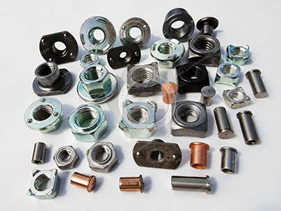
Weld nuts solve this problem by permanently attaching a threaded nut to the parent sheet through resistance welding, projection welding, or another qualified welding process.
 |  |
Unlike rivet nuts, which create a mechanical interlock through deformation of a sleeve, weld nuts become an integral part of the sheet-metal assembly through a controlled weld interface.
This makes weld nuts particularly useful when:
The rear side of the sheet is inaccessible after assembly
A permanent threaded attachment point is required
High-volume automated production is required
Repeated bolt installation is expected
A consistent nut position is required
The assembly must accommodate a thin sheet that cannot provide sufficient tapped-thread engagement
However, a weld nut is only as reliable as the complete welded joint. Nut geometry, projection design, sheet material, sheet thickness, surface condition, welding current,
electrode force, weld time, coating, alignment, and post-weld inspection all influence final performance.
 |  |
This technical guide provides design engineers, sheet-metal fabricators, automotive engineers, and strategic procurement managers with an engineering framework covering:
Weld Nut Geometries & Standards: Comparing square, hexagonal, flanged, T-type, and pilot-style weld nuts across applicable international product standards and customer specifications.
Resistance Welding & Process Parameters: Understanding projection welding physics, current density, electrode force, weld time, projection geometry,and thermal distortion in carbon steel, stainless steel, and other compatible sheet materials.
Sheet Metal Design: Selecting the correct nut configuration according to sheet thickness, access, hole geometry, load direction, and production process.
Comparative Selection Analysis: Evaluating weld nuts against self-clinching nuts and blind rivet nuts.
Quality & Procurement: Establishing material, weld, thread, coating, inspection, traceability, and sourcing requirements for industrial and automotive production.
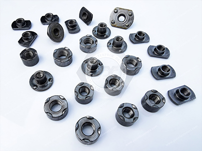 |  |
Selecting the correct weld nut geometry is essential for positioning accuracy, welding stability, load transfer, automated feeding, and final assembly performance.
Different weld-nut configurations use different projection and positioning features.
Therefore, engineers should specify the actual product geometry and applicable standard rather than assuming that all weld nuts are interchangeable.
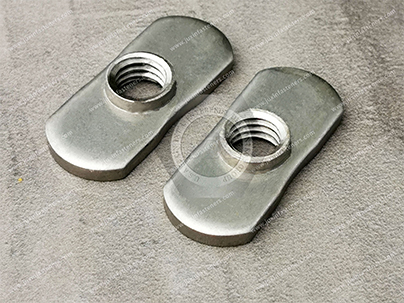
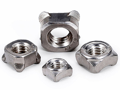
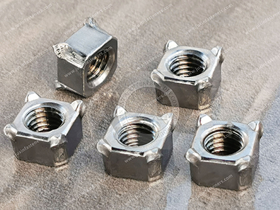
Common configurations include square weld nuts, hexagonal weld nuts, flanged weld nuts, T-type or pilot-style weld nuts, and customer-specific projection weld nuts.
| Weld Nut Type | Applicable Standard / Specification | Design Features & Positioning Elements | Primary Industrial Application |
|---|---|---|---|
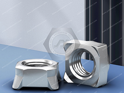
| Square Weld Nuts | DIN 928 and applicable customer / OEM specifications | Square body with welding projections and positioning features; suitable for controlled orientation and automated feeding | Electrical enclosures, switchgear cabinets, automotive brackets, general sheet-metal fabrication |
| Hexagonal Weld Nuts | DIN 929 and applicable customer / OEM specifications | Hexagonal body with welding projections; provides rotational stability and positive positioning during assembly | Automotive chassis, tubular frames, structural brackets, machinery assemblies |
| Flanged Weld Nuts | Applicable product and customer specifications | Integrated flange distributes bearing load and provides a larger mounting interface | High-load brackets, sheet-metal structures, dynamic machinery and automotive components |
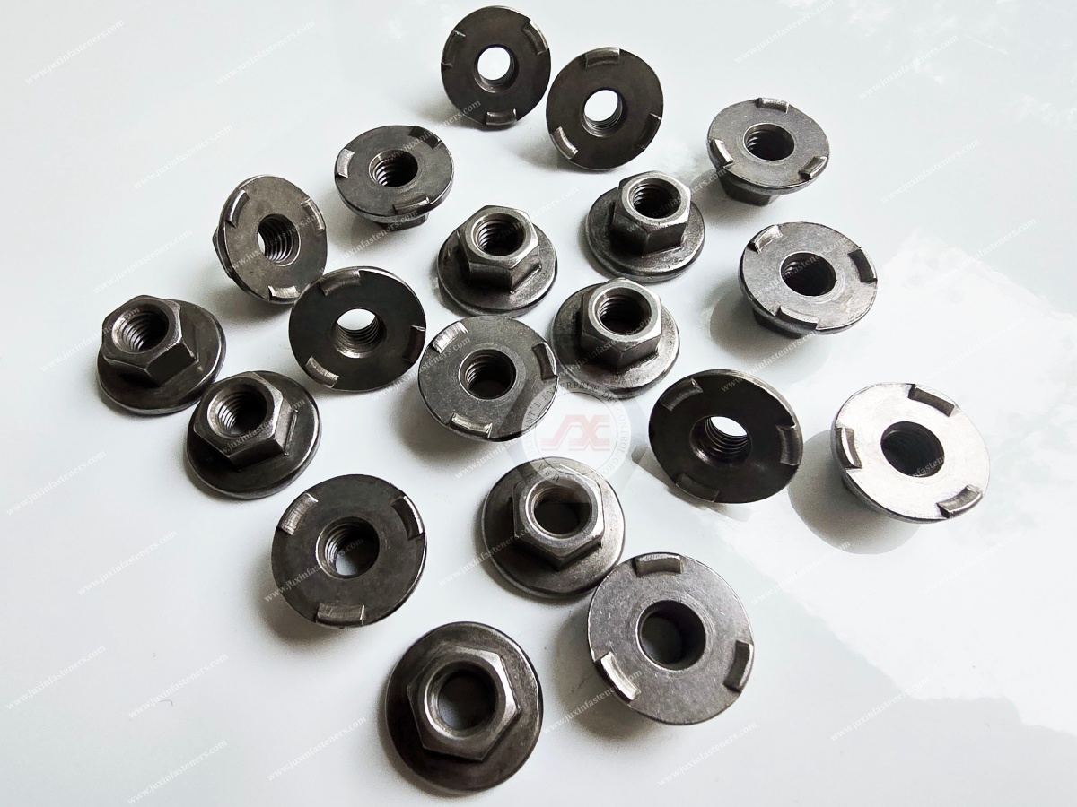
| T-Type / Pilot Weld Nuts | Application-specific / specialized specifications | Extended pilot or guide feature assists positioning and can help locate the nut in a prepared opening | Commercial vehicles, structural brackets, thicker sheet assemblies, guided installation systems |
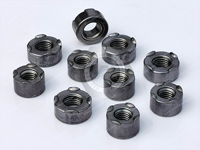
| Projection Weld Nuts | Applicable DIN / ISO / OEM specifications | Controlled projections concentrate welding current and create localized weld zones | Automotive BIW, battery enclosures, electrical cabinets and high-volume sheet-metal production |
A critical procurement point is that DIN 928 and DIN 929 should not be treated as generic certification labels for every weld nut design. They describe specific product configurations and dimensions. For custom weld nuts, the engineering drawing should define the geometry, material, thread, projections, dimensions, tolerances, and welding requirements.
 |  |
The basic geometry of a weld nut influences both installation and service performance.
Square weld nuts are useful where controlled orientation and rotational resistance are required.
Typical advantages include:
Positive positioning
Stable resistance-welding contact
Suitable geometry for automated feeding
Good rotational resistance after welding
Availability in different thread sizes and materials
Typical applications include:
Electrical cabinets
HVAC enclosures
Automotive brackets
Sheet-metal frames
Industrial machinery
Hexagonal weld nuts are widely used where the nut needs to resist rotation during bolt tightening and provide a stable welding interface.
Applications include:
Automotive chassis components
Body structures
Tubular frames
Machinery brackets
Industrial sheet-metal assemblies
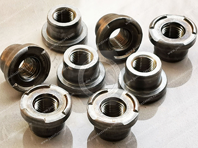 | 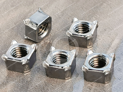 |
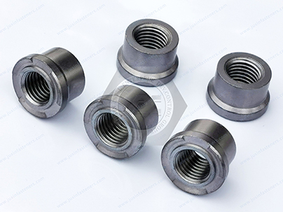
A flanged weld nut incorporates a larger bearing surface.
The flange can help:
Distribute clamping load
Reduce local sheet deformation
Increase support around the threaded hole
Improve stability on thinner or softer sheet materials
The actual load distribution depends on sheet thickness, material strength, flange geometry, preload, and joint design.
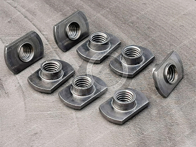
T-type or pilot-style configurations can be selected when accurate positioning is particularly important.
The pilot can assist with:
Hole location
Nut alignment
Automated assembly
Prevention of lateral movement before welding
For applications where weld spatter entering the thread is a concern, the nut geometry and welding process should be designed together.
A pilot feature alone should not be treated as a universal thread-protection solution.
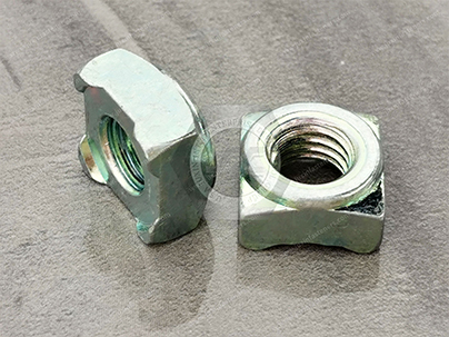 | 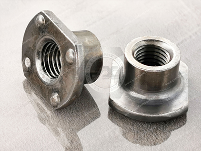 |
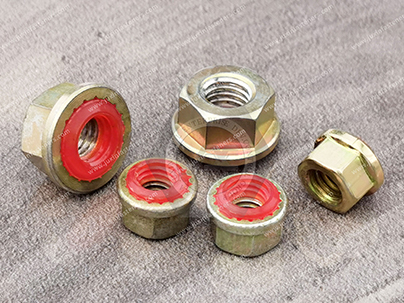
The primary engineering advantage of a weld nut is its permanent attachment to the parent sheet through a controlled welding process.
Unlike a blind rivet nut, which relies on deformation and mechanical interlocking of the insert body, a resistance-welded nut creates localized metallurgical bonding between the nut projections and the sheet.
 |  |
WELD NUT VS. RIVET NUT MECHANISM COMPARISON

   WELD NUT (Resistance / Projection Weld)       RIVET NUT (Mechanically Deformed)
   +-----------------------------+               +-----------------------------+
   |  [Localized Weld Zones]     |               |  [Deformed Sleeve]         |
   |       ||                    |               |         ||                  |
   |  =========================  |               |  ~~~~~~~~~~~~~~~~~~~~~~~~~  |
   |  Parent Sheet               |               |  Hole Wall / Sheet         |
   +-----------------------------+               +-----------------------------+

   * Permanent welded attachment                 * Mechanical deformation
   * Suitable for high-volume production         * Suitable for blind access
   * High repeatability when process is          * Removable/replacement option
     properly controlled                          * No welding equipment required
The difference should not be simplified into "weld nuts are always stronger."
A correctly designed weld-nut joint can provide excellent resistance to torque and pull-out, but actual performance depends on:
Number and geometry of weld projections
Weld current
Weld time
Electrode force
Sheet material
Sheet thickness
Nut material
Surface condition
Coating
Weld area
Loading direction
Distance to sheet edges
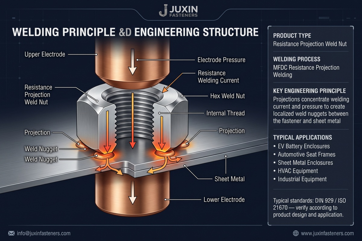
During resistance projection welding, electrical current passes through a localized contact area. The electrical resistance at the projections generates heat according to the fundamental relationship:
$$Q = I^2Rt$$
Where:
$Q$ = generated heat
$I$ = welding current
$R$ = electrical resistance of the welding interface
$t$ = welding time
The projections concentrate current and heat in localized areas.
As the material reaches the required welding temperature, the projections collapse and form localized welded zones under electrode pressure.
The process must be controlled so that sufficient weld area is created without excessive:
Spatter
Expulsion
Sheet indentation
Nut deformation
Thread damage
Heat-affected distortion
Electrode sticking
The weld interface creates a metallurgically bonded region between the nut and parent sheet.
However, it is not accurate to state that the weld zone will always exceed the tensile strength of the surrounding sheet.
Actual weld strength depends on:
Weld nugget area
Material combination
Sheet thickness
Projection geometry
Heat input
Electrode force
Current profile
Surface condition
Load direction
The engineering objective is therefore to create a repeatable weld interface with sufficient strength for the specified service loads.
Standard weld nuts intended for resistance welding are commonly supplied in a condition suitable for the welding process.
Depending on the application, this may mean:
Uncoated
Lightly oiled
Weld-compatible coating
Application-specific plating
Post-weld corrosion protection
Heavy metallic coatings or organic coatings at the welding interface can alter electrical resistance, heat generation, weld quality, electrode life, and fume generation.
For this reason, the coating system must be specified together with the welding process.
For high-strength fasteners, coating selection should also account for hydrogen-embrittlement risk, friction requirements, and the final service environment.
To achieve consistent weld quality, design engineers must consider both the fastener geometry and the sheet-metal manufacturing process.
A key engineering principle is that there is no single universal resistance-welding current, electrode angle, weld time, or sheet-flatness limit for every weld nut.
Actual parameters depend on:
Nut projection geometry
Nut material
Sheet material
Sheet thickness
Surface condition
Coating
Electrode diameter
Electrode force
Welding current
Weld time
Current waveform
Machine characteristics
The following table should therefore be treated as a design and process-development framework, not a universal welding parameter specification.
+-------------------------------------------------------------------------------------------------+
|                              SHEET METAL WELD NUT DESIGN FACTORS                                |
+------------------------------------+--------------------------------+---------------------------+
| Design / Process Parameter         | Engineering Consideration      | Primary Objective         |
+------------------------------------+--------------------------------+---------------------------+
| Parent Plate Flatness              | Maintain sufficient contact    | Prevent gaps and unstable |
|                                    | between projections and sheet  | welding conditions        |
+------------------------------------+--------------------------------+---------------------------+
| Projection Geometry                | Match nut design to sheet      | Concentrate current and   |
|                                    | thickness and material        | form repeatable welds     |
+------------------------------------+--------------------------------+---------------------------+
| Electrode Alignment                | Maintain controlled alignment | Stable current path and   |
|                                    | with the nut and sheet        | uniform pressure          |
+------------------------------------+--------------------------------+---------------------------+
| Welding Current                    | Establish through process     | Adequate heat generation  |
|                                    | development and validation    | without excessive expulsion|
+------------------------------------+--------------------------------+---------------------------+
| Electrode Force                   | Validate for material and     | Control projection        |
|                                    | projection geometry           | collapse and contact      |
+------------------------------------+--------------------------------+---------------------------+
| Weld Time                          | Validate with current and     | Repeatable weld formation |
|                                    | electrode force               | and thermal control       |
+------------------------------------+--------------------------------+---------------------------+
| Carbon Equivalent / Material      | Evaluate actual material      | Control weldability and   |
|                                    | chemistry and process         | HAZ cracking risk         |
+------------------------------------+--------------------------------+---------------------------+
The original version used specific TIG electrode and filler-wire angles.
Those parameters are not appropriate as universal weld-nut resistance-welding specifications because projection weld nuts are generally installed through resistance welding rather than TIG welding.
If a secondary arc-welding operation is used for a specific repair or custom assembly, its welding parameters must be specified separately.
Raw materials should conform to the engineering drawing and welding procedure.
The sheet should be:
Correct material grade
Correct thickness
Properly formed
Free of excessive oil and contamination
Free of burrs at the weld location
Within the specified dimensional tolerances
The original article proposed a universal flatness requirement of ≤0.2%.
This should instead be treated as an example engineering limit only when supported by the customer's drawing or welding process validation.
The critical requirement is to maintain reliable contact between the weld nut projections and the parent sheet.
Where the weld nut uses a pilot, locating feature, or prepared opening, the hole diameter and positional tolerance are important.
Incorrect hole size can cause:
Nut misalignment
Projection instability
Reduced weld area
Thread eccentricity
Assembly interference
For automated automotive production, positional accuracy should be specified according to the assembly drawing and fixture capability.
After welding:
Remove loose weld spatter.
Inspect the weld attachment.
Protect exposed parent-metal areas where corrosion protection has been affected.
Keep abrasive material away from internal threads.
Clean the threaded hole before final bolt installation.
Verify that the thread remains within the specified tolerance.
For panels requiring painting, e-coating, powder coating, or other finishing processes, the weld nut must be compatible with the complete finishing sequence.
Internal threads may require temporary protection during painting or coating operations depending on the final assembly process.
A typical automated production sequence can be represented as:
Sheet Preparation
       ↓
Nut Feeding / Positioning
       ↓
Nut Projection Contact
       ↓
Electrode Alignment
       ↓
Welding Current Applied
       ↓
Projection Collapse / Weld Formation
       ↓
Electrode Hold / Cooling
       ↓
Visual & Dimensional Inspection
       ↓
Weld Strength Verification
       ↓
Final Surface Treatment
       ↓
Thread Inspection
       ↓
Assembly
Process monitoring can include:
Welding current
Welding time
Electrode force
Electrode displacement
Electrical resistance
Weld energy
Electrode condition
Weld-spatter monitoring
Nut position
Weld integrity
For high-volume automotive production, process monitoring is especially valuable because weld quality can drift as electrodes wear, surfaces change, or welding equipment characteristics change.
Understanding failure modes is essential for both engineering design and procurement.
The welded region may fail under excessive pull-out or shear loading.
Potential causes include:
Insufficient weld energy
Incorrect electrode force
Poor projection geometry
Contaminated surface
Incorrect sheet thickness
Electrode wear
The weld nut may remain attached while the surrounding sheet tears.
This can indicate that the parent sheet or local reinforcement is the limiting component.
Possible solutions include:
Increasing sheet thickness
Increasing flange size
Adding reinforcement
Changing nut geometry
Increasing weld area
Changing load distribution
During bolt installation or removal, excessive torque can cause:
Weld fracture
Nut deformation
Sheet deformation
Thread stripping
Therefore, the required assembly torque must be evaluated together with weld torque-out performance.
Potential causes include:
Incorrect thread specification
Welding spatter
Coating buildup
Cross-threading
Tool misalignment
Thread deformation during welding
Thread gauges should be used when required by the quality plan.
JUXIN FASTENERS weld nuts and sheet-metal fastening systems can be applied across demanding industrial sectors where a permanent threaded attachment point is required.
Typical applications include:
Seat and seat-bracket structures
Chassis components
Cross-members
Body-in-White (BIW) structures
Door assemblies
Instrument panel brackets
Underbody components
Wiring brackets
Heat-shield attachments
Weld nuts allow threaded attachment points to be integrated directly into stamped sheet-metal components without requiring a conventional loose nut during final assembly.
For safety-related automotive components, the actual weld-nut design and validation must follow the customer's engineering specification and applicable vehicle safety requirements.
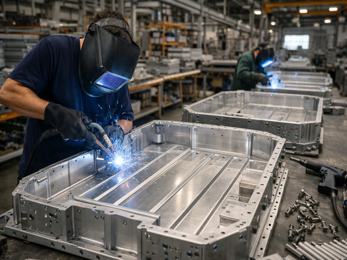
EV battery systems use numerous sheet-metal and aluminum structural components.
Potential weld-nut applications include:
Battery enclosure brackets
Cooling-system supports
Electrical component brackets
Cable management
Grounding points
Thermal management assemblies
Cover and shield attachments
Battery enclosure applications require additional attention to:
Corrosion
Sealing
Electrical isolation
Thermal cycling
Aluminum-steel compatibility
Assembly torque
Long-term vibration
Weld nuts are widely suited to:
Electrical control cabinets
Switchgear enclosures
HVAC equipment
Industrial machinery
Automation systems
Medical equipment frames
Sheet-metal machine guards
Electrical boxes
Square and hexagonal weld nuts can provide stable threaded mounting points where access to the back side of the panel is limited after fabrication.
Potential applications include:
Inverter boxes
Battery cabinets
Energy-storage equipment
Rail interior brackets
Electrical cabinets
HVAC modules
Equipment mounting frames
Dynamic vibration environments require the complete joint to be engineered for the expected load spectrum.
A weld nut provides a permanent attachment, but it does not automatically eliminate bolt loosening; the bolt, preload, thread friction, joint stiffness, and locking method must still be considered.
For procurement managers and strategic sourcing specialists evaluating sheet-metal fastening solutions, the following matrix compares weld nuts with self-clinching nuts and blind rivet nuts.
| Selection Metric | Weld Nuts (Square / Hex) | Self-Clinching Nuts | Rivet Nuts (Blind Thread Inserts) |
|---|---|---|---|
| Installation Method | Resistance / projection welding | Press-fit / mechanical clinching | Manual or pneumatic pull-setting tool |
| Access Requirement | Usually requires controlled electrode access to the weld location; process depends on equipment and assembly geometry | Typically requires access for pressing the fastener into the sheet | Single-sided blind installation possible |
| Joint Permanence | Permanent welded attachment | Permanent mechanical interference fit | Mechanically deformed attachment; replaceable if required |
| Welding Equipment | Required | Not required | Not required |
| Production Speed | Very high when integrated into automated production | High when press-fit equipment is available | High, particularly for blind-access assembly |
| Thin-Sheet Compatibility | Excellent when nut projection and sheet thickness are properly matched | Requires suitable ductile sheet and thickness | Suitable across a wider range of blind-access applications |
| Vibration Performance | Strong permanent nut attachment when properly welded; bolt locking still requires separate consideration | Strong mechanical retention when correctly installed | Depends on insert design, installation quality, sheet condition and joint loading |
| Blind-Side Installation | Generally limited by welding-electrode access | Requires access appropriate to the press-fit process | Excellent for single-sided installation |
| Typical Application | Automotive BIW, battery enclosures, brackets, high-volume sheet-metal production | Electrical enclosures, panels, brackets, machinery | Field assembly, closed profiles, tubular structures, retrofit applications |
| Primary Procurement Focus | Weldability, projection geometry, weld strength and process capability | Sheet ductility, installation force, push-out and torque-out | Hole size, grip range, pull-setting process and retention |
The correct choice depends on the manufacturing process and assembly architecture.
The production process already includes resistance welding.
A permanent threaded attachment is required.
High-volume automated manufacturing is planned.
The rear side of the panel will be inaccessible after assembly.
The parent sheet is compatible with projection welding.
Nut positioning must be highly repeatable.
Welding is undesirable.
The sheet material and thickness are suitable for clinching.
Press installation is available.
Heat distortion must be avoided.
A mechanically retained permanent nut is preferred.
Only one side of the assembly is accessible.
Welding equipment is unavailable.
The component is already fabricated.
Field repair or retrofit is required.
The joint may need replacement without welding.
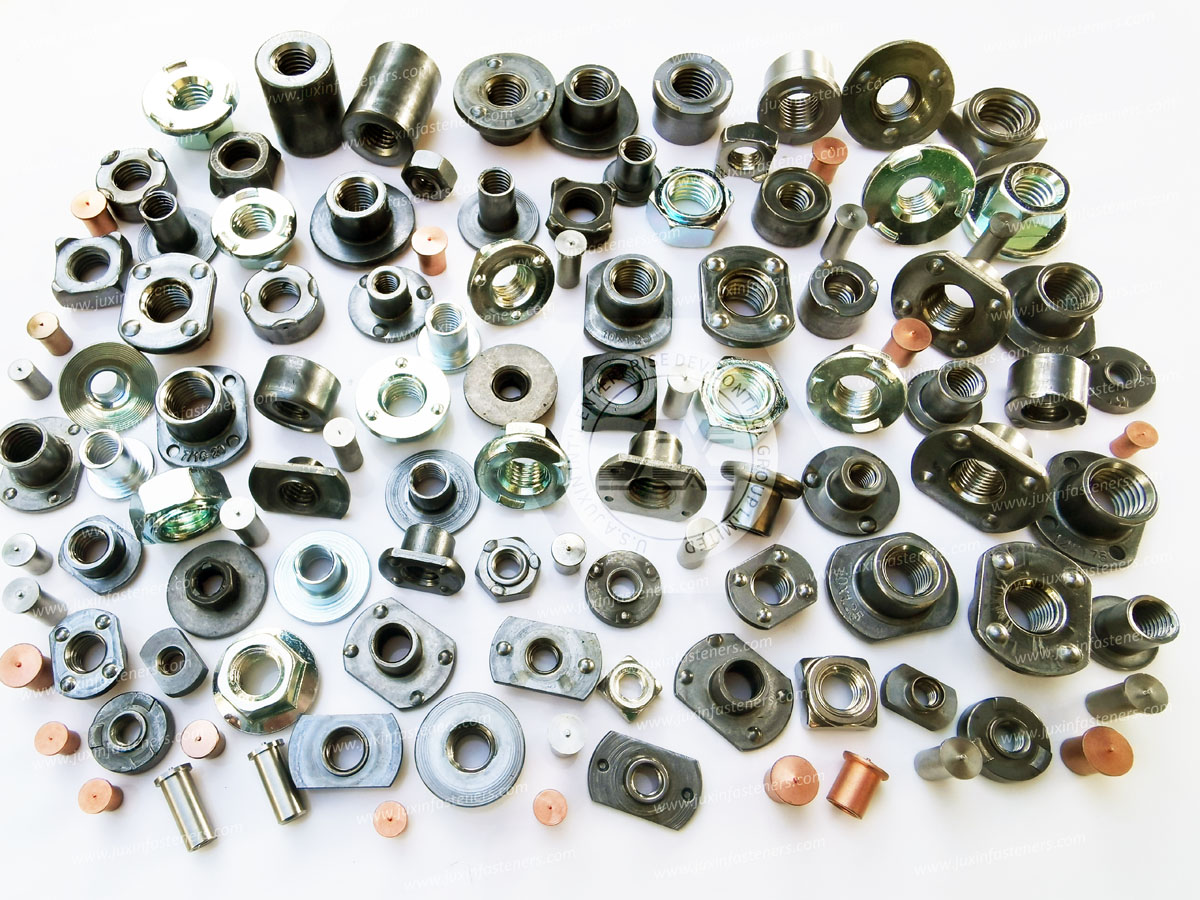
A professional weld-nut RFQ should contain enough information for the supplier to select the correct manufacturing route and validate the finished product.
Specify:
Weld nut type
Square / hexagonal / flanged / T-type / pilot configuration
Nut height
Flange diameter
Projection geometry
Overall dimensions
Thread size
Thread pitch
Thread tolerance
Material
Specify:
Material grade
Sheet thickness
Surface condition
Coating
Hole diameter if applicable
Hole positional tolerance
Welding access
Required weld location
Specify:
Resistance or projection welding
Welding machine type
Electrode configuration
Required weld strength
Weld monitoring requirements
Process validation requirements
Specify:
Bare / uncoated condition
Zinc plating
Zinc-nickel
Zinc-flake
Stainless steel
Organic coating
Post-weld corrosion protection
Coating requirements should be evaluated together with the welding process because coating can affect electrical resistance and weld formation.
Depending on the program, procurement may require:
Material certificates
Dimensional inspection reports
Thread inspection
Weld strength results
Coating thickness
Coating adhesion
Corrosion test reports
Batch traceability
Process capability documentation
PPAP documentation where applicable
Customer-specific quality records
Expand your technical engineering reference library with related JUXIN FASTENERS documentation:
Broken Weld Fastener Extraction & Quality Inspection Guide
https://www.juxinfasteners.com/technical-guide/welding-screw-repair-inspection-guide/
Field repair procedures for broken weld studs and weld fasteners, coating inspection, corrosion testing, thread inspection, and replacement procurement.
Precision Projection Weld Studs & Sheet Metal Fastening Guide
https://www.juxinfasteners.com/industrial-solutions/projection-weld-studs-sheet-metal-fastening-guide/
Engineering principles for projection weld studs, sheet-metal fastening, welding mechanics, and industrial applications.
EV Automotive Fasteners & Lightweight Joining Solutions
https://www.juxinfasteners.com/automotive-solutions/ev-fasteners-lightweight-joining-ultra-high-strength-bolts/
EV battery fasteners, high-strength automotive bolts, lightweight joining, aluminum-steel compatibility, self-clinching hardware, and battery enclosure applications.
Preventing Bolt Loosening & Fatigue Failure Solutions
https://www.juxinfasteners.com/technical-guide/bolt-loosening-fatigue-failure-prevention-solutions/
Engineering analysis of preload loss, transverse vibration, rotational loosening, fatigue, and high-vibration joint design.
Automotive Wheel Fasteners & Lightweight Aluminum Joinery Guide
https://www.juxinfasteners.com/automotive-solutions/wheel-hub-bolts-nuts-aluminum-body-fasteners/
Automotive wheel fasteners and lightweight aluminum joining technologies.
Threaded Inserts for Plastics: Engineering Installation Guide
https://www.juxinfasteners.com/industrial-solutions/thread-insert-nuts-engineering-installation-guide/
Comparison of threaded inserts and alternative fastening methods for automotive electronic housings and engineered plastics.
JUXIN FASTENERS manufactures and supplies square weld nuts, hexagonal weld nuts, flanged weld nuts, projection weld nuts,
and other custom sheet-metal fastening components for automotive, EV, industrial machinery, electrical, HVAC, and enclosure applications.
Our manufacturing and sourcing capabilities support requirements involving:
Square weld nuts
Hexagonal weld nuts
Flanged weld nuts
Projection weld nuts
Automotive weld nuts
EV battery enclosure weld nuts
Custom weld fasteners
Weld studs
Projection weld studs
CD weld studs
Self-clinching fasteners
High-strength fasteners
Custom cold-formed components
For engineering and procurement projects, JUXIN FASTENERS can discuss requirements involving:
Custom weld nut drawings
Thread specifications
Material selection
Projection geometry
Parent-sheet compatibility
Welding process requirements
Surface treatment
Corrosion protection
Dimensional inspection
Mechanical and weld testing
Samples
Custom tooling
Production specifications
Quality documentation
Bulk procurement RFQs
For technical data sheets, custom drawing reviews, sample development, or production sourcing:
Official Corporate Website:
https://www.juxinfasteners.com
Engineering & Sourcing Email:
info@juxinfasteners.com
Core Product Capabilities:
Weld Nuts, Square Weld Nuts, Hexagonal Weld Nuts, Flanged Weld Nuts, Projection Weld Nuts,
Projection Weld Studs, Self-Clinching Fasteners, High-Strength Fasteners, and Custom Cold-Formed Industrial Hardware.
The most important point when selecting a weld nut is that the nut itself is only one part of the fastening system.
Reliable performance depends on the interaction between:
Weld Nut Geometry + Fastener Material + Parent Sheet + Projection Design + Welding Process + Surface Treatment + Joint Loading + Inspection
A square weld nut may be the right solution for one enclosure, while a hexagonal weld nut, flanged weld nut, self-clinching nut, or blind rivet nut may be more appropriate for another.
For automotive, EV, industrial machinery, electrical enclosure, HVAC, rail transit, and sheet-metal fabrication applications,
procurement teams should therefore specify the complete joint rather than purchasing a weld nut based only on thread size.
The best weld nut specification answers five fundamental questions:
What material is the parent sheet?
What is the sheet thickness and joint load?
What weld process and production equipment will be used?
What corrosion, coating, and assembly requirements apply?
What inspection and traceability requirements must the supplier meet?
When these factors are defined together, weld nuts can provide a highly repeatable, production-efficient method for creating permanent threaded attachment points in thin-sheet and structural assemblies.
 MORE NEWS

Sep. 25, 2026

Sep. 25, 2026

Sep. 25, 2026
Contact Us
Tel.:
+86 020 8621 0320
+86 020 3121 6067
E-mail:
Technical Support:
Navigation
SEND INQUIREY