
Call Us
+86 136 6007 9809
Call Us
+86 136 6007 9809

Jun. 20, 2023
Electric vehicle battery pack assembly is not simply a process of joining a battery cover to a tray with bolts.
Modern EV battery systems integrate battery modules, lightweight aluminum structures, cooling components,
battery management systems (BMS), power electronics, sealing interfaces, electrical insulation, and structural mounting points within a compact assembly.
These combinations create a fastening environment in which engineers must consider more than fastener diameter, thread size, or strength class.
The fastening system may need to account for:
Different coefficients of thermal expansion between steel, aluminum, and polymer components
Galvanic corrosion risk at dissimilar-metal interfaces
Local bearing and pull-through strength of aluminum sheet
Thread stripping and boss failure in polymer components
Joint preload retention under vibration and thermal cycling
Hole size and positional tolerance
Sealing requirements around battery enclosure interfaces
Electrical insulation where required
Coating compatibility with aluminum and other mating materials
Automated assembly and torque-control capability
Serviceability and replacement requirements
Manufacturing tolerances across large battery enclosure assemblies
For sealed battery packs, one engineering distinction is particularly important:
A fastener can contribute to an IP-rated battery enclosure design, but the fastener itself does not independently guarantee an IP67 rating.
Ingress-protection performance belongs to the completed enclosure system. Housing geometry, gaskets or seals, joint compression, fastener spacing,
surface flatness, cable interfaces, vents, plugs, manufacturing variation, and the final assembly process can all influence sealing performance.
The completed assembly should therefore be validated against the applicable enclosure protection requirements.
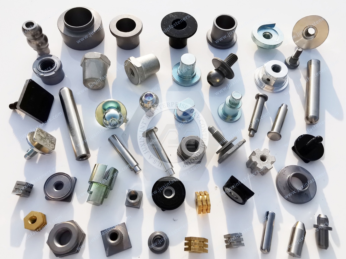
JUXIN FASTENERS supports EV battery pack and automotive fastening projects involving high-strength bolts, locking fasteners, blind rivet nuts,
weld fasteners, self-clinching fasteners, threaded inserts, polymer fastening components, and custom drawing-based parts.
This guide focuses on how these fastening technologies interact with battery pack assembly, joint engineering, manufacturing, and sourcing decisions.

Before selecting a fastener, engineers should first define what the connection must accomplish.
Different battery pack joints may need to provide:
Structural clamping
Permanent captive threads
One-sided installation
Reinforced threads in aluminum
Threads in polymer components
Controlled gasket compression
Resistance to vibration-induced loosening
Electrical isolation
Component spacing
Serviceable attachment
Permanent sheet joining
Alignment or location
These functions should not automatically use the same fastening technology.
A structural battery-frame bolt, for example, performs a fundamentally different function from a blind rivet nut installed in a thin enclosure wall.
Similarly, a fastener responsible for clamping should not automatically be expected to provide precise component location unless the joint has been designed for both functions.
A useful engineering sequence is:
Joint Function → Parent Material → Load → Access → Installation Process → Fastener Type → Preload or Setting Requirement → Environmental Conditions → Validation
This approach helps prevent fastener selection from becoming a late-stage hardware purchasing decision.
A battery pack can contain several different mechanical assembly zones, and each zone can create a different fastening requirement.
Fasteners may be used for:
Module frames
Module supports
Brackets
Internal structural members
Sensor mounting
Electrical component mounting
Depending on the design, potential solutions include bolts, screws, threaded inserts, standoffs, spacers, and custom components.
The lower enclosure may contain:
Aluminum extrusions
Aluminum sheet
Cast aluminum components
Steel reinforcement
Cross-members
Mounting brackets
Machined interfaces
Potential fastening technologies include:
High-strength bolts
Flange bolts
Weld nuts
Weld studs
Blind rivet nuts
Self-clinching fasteners
Threaded inserts
Blind rivets
Custom fasteners
The battery cover may require:
Controlled clamp load
Gasket compression
Serviceability
Fastener-spacing control
Cover-flatness control
Corrosion protection
The fastening strategy should therefore be developed together with the enclosure sealing strategy.
Battery management and electrical assemblies may use:
Machine screws
Small threaded fasteners
Standoffs
Spacers
Threaded inserts
Plastic or nylon fasteners
PCB supports
Cable-management components
These applications may prioritize electrical isolation, compact packaging, positioning, and serviceability rather than high structural clamp load.
Cooling plates, manifolds, brackets, sensors, and other thermal-management components may introduce additional requirements involving:
Controlled clamping
Flatness
Thermal expansion
Corrosion
Coolant exposure
Sealing
Service access
Fastener selection should therefore follow the specific function of each assembly zone rather than applying one fastening specification throughout the complete battery pack.
Modern battery pack structures can combine:
Aluminum alloys
Carbon steel
Alloy steel
Stainless steel
Engineering polymers
Elastomeric seals
Composite materials
Electrical insulation materials
Thermal-interface materials
These materials should not be treated as mechanically equivalent.
Aluminum can support lightweight and integrated enclosure designs, but engineers should evaluate:
Local bearing strength
Thread stripping
Surface damage
Galvanic interaction
Thermal expansion
Joint stiffness
Coating compatibility
Simply replacing a steel component or fastener with aluminum does not automatically create a better lightweight joint.
The complete load path and joint architecture should be considered.
Components manufactured from PA6, PA66, PPS, PC/ABS, and other engineering polymers may require consideration of:
Polymer grade
Reinforcement
Moisture absorption
Creep
Temperature
Chemical exposure
Boss geometry
Thread form
Electrical insulation
Flame-performance requirements where applicable
Polymer designations should not be treated as interchangeable.
Where steel fasteners are used with aluminum or other materials, engineers may also need to consider:
Electrical continuity
Galvanic corrosion
Surface coatings
Isolation materials
Water retention
Drainage
Differential thermal expansion
Material selection and fastener selection should therefore be coordinated rather than handled as separate decisions.

When screws are installed directly into polymer bosses, thread engagement should be determined according to the actual assembly rather than by applying a universal multiple of nominal screw diameter.
Relevant variables include:
Polymer grade
Glass-fiber or other reinforcement
Screw geometry
Boss diameter
Boss wall thickness
Installation torque
Pull-out requirement
Service temperature
Thermal cycling
Creep
Repeated assembly
A useful engineering sequence is:
Thread Stripping Strength → Boss Strength → Pull-Out Resistance → Installation Torque → Assembly Variation → Thermal Cycling and Creep → Long-Term Joint Retention
Where repeated assembly or greater mechanical loading is required, a metal threaded insert may provide a more suitable interface than relying solely on molded polymer threads.
Potential solutions include:
Brass threaded inserts
Knurled brass inserts
Heat-set inserts
Ultrasonic inserts
Press-fit inserts
Self-tapping inserts
Molded-in inserts
Custom threaded bushings
Final insert selection should follow the parent material, boss design, installation method, and mechanical requirements.
Fastener tightening across a large battery enclosure cover should be coordinated with the gasket and enclosure geometry.
The engineering objective is not simply:
“Tighten every bolt to the same torque.”
The objective is to achieve the required joint compression and preload distribution without causing unacceptable enclosure distortion or damaging the sealing system.
Depending on the design, engineers may evaluate:
Target clamp load
Gasket compression
Cover flatness
Flange stiffness
Fastener spacing
Bolt preload
Friction
Torque scatter
Tightening tool capability
Assembly sequence
Leak-test results
A staged or cross-pattern tightening sequence may be appropriate for some multi-fastener cover designs, but no universal tightening percentage sequence should be applied to every battery enclosure.
The appropriate process should be established through joint testing and assembly validation.
ISO 16047 may be relevant when evaluating torque/clamp-force relationships for threaded fasteners.
High-strength bolts can be used in structural battery pack joints where the engineering design requires the corresponding mechanical properties.
Potential applications may include:
Battery structural frames
Battery-to-vehicle mounting
Enclosure reinforcement
Cross-members
Module-support structures
Structural brackets
Property classes such as 8.8 or 10.9 may be specified for particular applications, but they should not be treated as universal EV battery requirements.
Fastener selection should consider:
Required clamp load
Tensile loading
Shear loading
Fatigue
Joint stiffness
Mating thread strength
Grip length
Surface treatment
Friction condition
Tightening method
Corrosion environment
Customer or OEM specification
A higher-strength bolt does not automatically create a stronger joint.
In an aluminum assembly, for example, local bearing, thread strength, or deformation of the parent material may become the limiting condition before the bolt reaches its mechanical capacity.
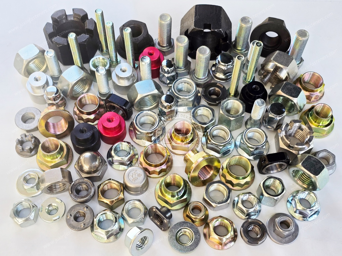
Battery enclosures frequently require captive threaded attachment points.
Several technologies can provide them, but they solve different manufacturing and assembly problems.
Projection weld nuts can provide permanent threaded attachment points in suitable weldable structures.
Selection should consider:
Parent material
Sheet thickness
Projection geometry
Weld process
Electrode access
Coating condition
Torque resistance
Final assembly requirement
Square weld nuts, hex weld nuts, flange weld nuts, and application-specific weld nut geometries may be evaluated according to the sheet-metal design and welding process.
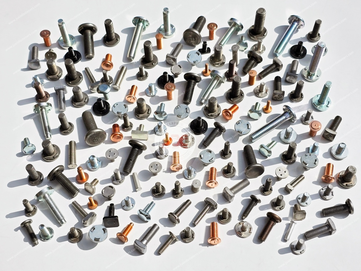
Weld studs can provide fixed threaded mounting points for brackets, electrical components, cable-management hardware, and other enclosure components.
The appropriate welding process depends on the stud design, substrate, load direction, and manufacturing requirements.
Self-clinching nuts, studs, and standoffs can provide captive features in compatible sheet materials.
Selection should consider:
Sheet material
Sheet hardness
Sheet thickness
Hole geometry
Edge distance
Installation force
Push-out requirement
Torque resistance
Blind rivet nuts can create reusable internal threads where backside access is unavailable.
Selection should consider:
Parent material
Sheet thickness
Grip range
Hole diameter
Hole shape
Anti-rotation requirement
Pull-out requirement
Spin-out requirement
Installation equipment
Service requirements
Threaded inserts may be used where aluminum, polymer, or other parent materials require reinforced threads.
The correct insert technology depends on the parent material, installation process, load requirement, and required service life.
Battery trays and enclosure structures may combine aluminum extrusions, sheet, castings, and steel reinforcement components.
Depending on material thickness, accessibility, structural requirements, production volume, and manufacturing process, joining methods may include:
| Joining Technology | Primary Function | Typical Battery Pack Relevance |
|---|---|---|
| Blind riveting | Permanent mechanical joining | Enclosures, brackets, and sheet assemblies |
| Blind rivet nuts | One-sided reusable threaded attachment | Closed profiles and inaccessible sheet |
| Self-piercing riveting | Mechanical interlock through sheet stack | Suitable multi-layer or mixed-material structures |
| Flow-drill screw joining | One-sided mechanically formed threaded joint | Suitable sheet and structural assemblies |
| Mechanical clinching | Local sheet interlock | Compatible thin-sheet assemblies |
| Weld nuts | Permanent captive threaded point | Weldable fabricated structures |
| Weld studs | Permanent stud attachment | Brackets, mounting points, and sheet structures |
| Self-clinching fasteners | Captive thread, stud, or standoff | Compatible sheet-metal assemblies |
| Conventional bolts and nuts | Structural or removable clamping | Joints with suitable access |
| Threaded inserts | Reinforced reusable thread | Aluminum, polymer, or other suitable parent materials |
No single joining technology is universally superior.
The appropriate process depends on joint function, material stack, production equipment, installation access, required serviceability, and validation requirements.
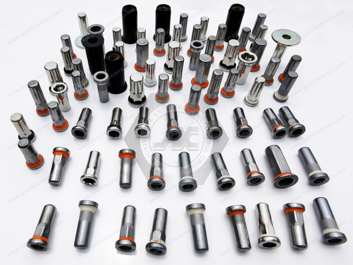
Blind rivet nuts can be particularly useful in aluminum battery enclosure structures where backside access is restricted.
Available solutions may include:
Round-body rivet nuts
Knurled-body rivet nuts
Half-hexagonal rivet nuts
Full-hexagonal rivet nuts
Open-end designs
Closed-end designs
Reduced-head designs
Flat-head designs
Application-specific sealing configurations
Anti-rotation requirements deserve particular attention.
A round-body rivet nut, knurled design, half-hexagonal body, and full-hexagonal body do not provide identical behavior in every parent material.
Hole geometry, substrate strength, setting process, and installation torque all influence performance.
Sealing-related versions may incorporate:
Elastomeric elements
Under-head seals
Sealing coatings
Sealants
Closed-end geometry
However, a sealing feature does not automatically guarantee IP67 performance.
A validated enclosure may require control of:
Hole diameter
Hole roundness
Material thickness
Grip range
Rivet-nut setting
Flange geometry
Seal compression
Gasket material
Fastener spacing
Cover flatness
Tightening process
Installation equipment
Leak testing
Thermal cycling
Environmental exposure
The appropriate engineering statement is:
A sealed blind rivet nut can contribute to an IP-rated enclosure design when integrated into a validated sealing system.
It should not be treated as an independent guarantee of the final enclosure IP rating.
Battery enclosures may require protection against:
Water
Dust
Road spray
Condensation
Coolant
Environmental contamination
Fasteners contribute to the sealing architecture through clamp load, spacing, retention, and local interface design.
But final sealing performance can also depend on:
Fastener Preload + Flange Stiffness + Gasket Geometry + Gasket Compression + Surface Flatness + Fastener Spacing + Cover Deformation + Temperature Cycling + Manufacturing Variation + Environmental Validation
This creates an important sourcing distinction.
A procurement specification should not simply request a “waterproof bolt” or “IP67 rivet nut” when the actual requirement belongs to the completed enclosure.
Engineering and procurement teams should instead define whether the application requires:
Water resistance
Splash resistance
Leak prevention
Dust protection
An IP-rated enclosure
Coolant containment
Pressure control
Chemical resistance
These are not interchangeable requirements.
EV battery assemblies can experience vibration, cyclic loading, and thermal changes.
Fastener self-loosening and preload loss can be influenced by:
Initial preload
Transverse displacement
Joint stiffness
Friction
Interface settlement
Fastener geometry
Thread geometry
Temperature
Repeated assembly
Locking mechanism
The engineering process should therefore begin with the joint rather than with the locking device.
A useful sequence is:
Joint Load → Required Clamp Force → Fastener Selection → Joint Stiffness → Torque/Tension Relationship → Preload Variation → Vibration and Thermal Cycling → Locking Strategy → Validation
Potential locking technologies include:
These can be considered where a metallic prevailing-torque mechanism is required.
Performance depends on nut design, material, coating, temperature, and installation history.
Non-metallic insert lock nuts can provide prevailing torque in suitable applications.
Temperature, chemical exposure, polymer aging, and reuse requirements should be evaluated for the actual application.
Wedge-locking systems may be considered for joints where the design requires additional resistance to loosening caused by transverse movement.
Serrated interfaces can provide rotational resistance but require careful evaluation on softer aluminum surfaces because local surface damage can affect contact conditions, coating integrity, and preload behavior.
ISO 2320 provides functional requirements and test methods for applicable prevailing-torque steel nuts.
A universal reuse count or temperature limit should not be assigned to every locking nut design without the corresponding product qualification and application specification.
Steel-to-aluminum interfaces require corrosion engineering when electrical contact and environmental exposure can create conditions for galvanic corrosion.
Risk depends on multiple variables, including:
Alloy composition
Surface condition
Coating
Electrolyte exposure
Humidity
Water retention
Joint geometry
Electrical continuity
Cathode-to-anode area relationship
Temperature
Drainage
Salt exposure
Coating damage
A single voltage-difference threshold should therefore not be used as a universal rule for determining galvanic corrosion risk.
Select material combinations compatible with the mechanical and environmental requirements.
Where compatible with joint requirements, possible approaches can include:
Polymer washers
Insulating coatings
Isolation films
Non-conductive sealants
Composite barriers
Depending on the specification, steel fasteners may use:
Zinc plating
Zinc-nickel plating
Zinc-flake coating systems
Organic topcoats
Application-specific protective systems
Even an appropriate coating system can perform poorly if the assembly traps water or electrolyte around the fastener.
Battery pack design should therefore consider drainage, seal continuity, crevice geometry, edge protection, and possible coating damage during installation.
Surface treatment can influence:
Corrosion resistance
Friction
Tightening behavior
Dimensional fit
Electrical interaction
Appearance
Potential treatments can include:
Zinc plating
Zinc-nickel plating
Zinc-flake systems
Black oxide
Nickel plating
Passivation for suitable stainless steel components
Organic topcoats
PTFE-based coatings
Customer-specified treatments
For high-strength steel fasteners, surface-treatment selection also requires consideration of hydrogen-embrittlement risk.
The engineering issue is not simply corrosion resistance.
It involves the interaction between:
Steel Strength + Heat Treatment + Surface Treatment + Hydrogen Exposure + Process Controls + Service Environment
ISO 4042 addresses electroplated coating systems for steel fasteners and includes requirements and recommendations related to hydrogen-embrittlement risk management.
ISO 10683 may be relevant for applicable zinc-flake coating systems.
The correct engineering objective is not to claim “zero hydrogen embrittlement.”
The objective is to control the manufacturing and coating processes and verify the finished fastener against the applicable specification.
Battery pack assemblies may experience significant temperature variation during operation and environmental exposure.
Aluminum and steel have different coefficients of thermal expansion.
A simplified representation of differential free thermal expansion is:
ΔL = L(α₁ − α₂)ΔT
where:
L = characteristic length
α₁ = coefficient of thermal expansion of material 1
α₂ = coefficient of thermal expansion of material 2
ΔT = temperature change
However, this calculation does not directly provide the change in bolt preload in an assembled joint.
Actual joint response also depends on:
Bolt stiffness
Clamped-member stiffness
Joint geometry
Grip length
Fastener diameter
Material elasticity
Contact conditions
Thermal expansion of the individual components
Structural constraints
This is why long or highly constrained aluminum-to-steel battery joints may require additional joint analysis rather than simply selecting a higher-strength bolt.
Thermal-cycle validation may need to evaluate:
Initial preload
Preload retention
Seal compression
Cover deformation
Joint slip
Fastener fatigue
Corrosion
Leakage
Electrical isolation where required
Not every fastener inside a battery pack is a structural enclosure fastener.
This distinction is important when developing a sourcing strategy.
Cooling plates, cooling channels, manifolds, brackets, sensors, and other thermal-management components may use:
Machine screws
Flange bolts
Locking nuts
Threaded inserts
Studs
Custom fasteners
CNC machined components
Selection may need to consider:
Parent material
Clamp-load requirement
Flatness
Thermal expansion
Corrosion
Coolant exposure
Chemical compatibility
Sealing
Serviceability
Where a fastening joint interacts with a coolant or sealing interface, the fastener should be evaluated as part of the complete thermal-management assembly.
BMS housings, sensors, electronic modules, and electrical support components may use:
Small machine screws
Threaded inserts
Self-clinching standoffs
Metal spacers
Plastic spacers
Nylon screws
Nylon nuts
Nylon washers
PCB supports
Cable clips
Custom insulating components
Engineering considerations may include:
Electrical isolation
Component spacing
Packaging
Temperature
Polymer creep
Chemical compatibility
Service access
Cable routing
Sensor positioning
Material and fastening technology should be selected according to the actual electrical and mechanical requirements.
The following matrix can help engineering and procurement teams narrow the initial fastening approach.
| Battery Pack Application | Potential Fastening Approach | Main Engineering Considerations | Key RFQ Question |
|---|---|---|---|
| Battery enclosure cover | Bolts + sealing interface | Preload, gasket compression, flange stiffness, corrosion | What clamp-load and sealing requirements apply? |
| Aluminum battery tray | Rivet nuts, inserts, bolts, compatible captive fasteners | Hole geometry, grip range, thread strength, galvanic interaction | What are the alloy, thickness, and access conditions? |
| Structural frame | High-strength or application-specific bolts | Strength, fatigue, preload, corrosion | What loads and joint requirements apply? |
| Weldable fabricated bracket | Weld nut or weld stud | Material, sheet thickness, welding process | Which welding process and load direction apply? |
| Thin compatible sheet | Self-clinching fastener | Sheet hardness, thickness, installation force | Is the sheet compatible with the clinching process? |
| Closed profile | Blind rivet nut | Access, grip range, pull-out, spin-out | What hole and grip range are available? |
| BMS housing | Screws and threaded inserts | Polymer creep, stripping, electrical isolation | Is repeated assembly required? |
| Cooling assembly | Bolts, screws, inserts, custom components | Flatness, preload, sealing, thermal cycling | Is the joint part of a coolant or sealing interface? |
| Service panel | Captive or removable fastener | Repeated access, retention, sealing | How frequently must the panel be removed? |
| Permanent sheet joint | Blind rivet or other mechanical joining technology | Material stack, grip, load, accessibility | What materials and thicknesses are being joined? |
This matrix should be treated as an initial engineering filter rather than a universal product specification.
Understanding how a joint can fail is often more useful than simply specifying a stronger fastener.
Possible contributors include:
Insufficient initial preload
Embedment
Surface settlement
Thermal effects
Joint slip
Torque variation
Incorrect friction assumptions
Possible contributors include:
Insufficient engagement
Weak parent material
Polymer creep
Excessive installation torque
Incorrect thread specification
Repeated assembly
Possible contributors include:
Incorrect hole size
Incorrect grip range
Insufficient setting
Unsuitable substrate
Incorrect body geometry
Installation variation
Possible contributors include:
Dissimilar-metal contact
Moisture
Coating damage
Salt exposure
Poor drainage
Incompatible surface treatment
Possible contributors include:
Incorrect gasket compression
Cover distortion
Surface-flatness variation
Fastener-spacing problems
Uneven preload
Seal degradation
Assembly variation
Possible contributors include:
Stress concentration
Insufficient preload
Joint slip
Cyclic loading
Geometry
Surface condition
Thread-root stresses
Failure analysis should consider the complete joint rather than attributing every failure to the fastener itself.
Fastener selection should also consider how the component will be installed in production.
For automated or semi-automated assembly, engineering teams may need to evaluate:
Fastener feeding
Orientation
Tool access
Installation speed
Torque control
Angle monitoring where applicable
Setting-force control
Fastener presence detection
Cross-threading risk
Hole-position variation
Assembly traceability
Inspection capability
A fastener can meet mechanical requirements but still create production problems if its geometry or installation method is incompatible with the assembly equipment.
Manufacturing feasibility should therefore be considered during fastener selection rather than after the joint has been released.
Standard fasteners should be used where they meet the engineering requirement.
Custom manufacturing becomes relevant when the application requires:
Non-standard dimensions
Special head geometry
Special shoulder geometry
Extended length
Reduced installation height
Integrated locating features
Special anti-rotation features
Application-specific sealing geometry
Drawing-controlled material
Customer-specific coating
Unique thread-to-body geometry
Integration with proprietary battery structures
Custom fasteners should solve a defined engineering or manufacturing problem rather than add complexity without functional benefit.
JUXIN FASTENERS can support drawing-based cold-formed, machined, stamped, and application-specific fastening components depending on geometry, material, quantity, and manufacturing feasibility.
A common sourcing problem occurs when a fastener RFQ contains only:
Part Name + Thread Size + Quantity
That information may be enough to identify a commodity fastener, but it is often insufficient for an application-specific EV battery joint.
For more efficient technical evaluation, the RFQ should define the available requirements in several groups.
Fastener type
Head style
Flange diameter
Thread size
Thread pitch
Length
Grip length
Under-head geometry
Washer requirement
Captive requirement
Aluminum alloy and temper
Steel grade
Polymer grade
Sheet thickness
Wall thickness
Cast material
Reinforcement where applicable
Carbon or alloy steel specification
Stainless steel grade
Aluminum alloy
Brass or copper alloy where applicable
Polymer grade
Heat treatment
Hardness
Tensile requirement
Proof or yield requirement where applicable
Torque/clamp-force requirement
Pull-out requirement
Spin-out resistance
Shear requirement
Fatigue requirement
Prevailing torque
Installation torque
Zinc
Zinc-nickel
Zinc-flake
Passivation
Topcoat
Sealant
Lubrication
Friction requirement
Coating thickness
Hydrogen-embrittlement controls where applicable
Manual or automated installation
Installation tool
Access direction
Installation torque
Required clamp force where specified
Setting method
Reuse requirement
Production-volume requirement
Temperature range
Thermal cycling
Humidity
Salt exposure
Coolant exposure
Chemical exposure
Vibration
Shock
Where applicable, specify:
Gasket type
Seal material
Compression requirement
Leak requirement
IP requirement
Temperature cycling
Chemical compatibility
Leak-test method
Quality requirements should be defined according to the actual automotive program, drawing, customer specification, and component criticality.
Depending on the project, documentation may include:
Material certificates
Dimensional inspection reports
Mechanical test reports
Coating thickness reports
Torque/clamp-force data
Prevailing-torque test data
Pull-out or spin-out test data
Corrosion test reports
Lot traceability
Certificate of conformity
Process-control documentation
Customer-specific PPAP documentation where required
PPAP requirements and submission levels should be agreed during project development rather than assumed as a universal deliverable for every fastener.
The same principle applies to corrosion testing, torque testing, dimensional capability, traceability, and other documentation.
Specify what the program actually requires.
For faster technical evaluation, an EV battery fastener RFQ should ideally include the following information where available.
Battery tray
Battery cover
Module assembly
BMS housing
Cooling plate
Structural frame
Aluminum enclosure
Power electronics enclosure
Service panel
Material specification
Aluminum alloy and temper
Steel grade
Sheet thickness
Wall thickness
Cast material
Polymer grade
Reinforcement where applicable
Fastener type
Thread
Diameter
Length
Head or flange geometry
Grip range
Material
Mechanical property class
Coating specification
Coating thickness
Lubrication
Friction requirement
Corrosion requirement
Manual or automated installation
Installation torque
Required clamp force where specified
Tool type
Access direction
Setting process
Reuse requirement
Temperature range
Thermal cycling
Humidity
Salt exposure
Coolant exposure
Chemical exposure
Vibration
Shock
Tensile
Shear
Pull-out
Spin-out
Fatigue
Prevailing torque
Corrosion
Sealing
IP requirement where applicable
Dimensional inspection
Mechanical testing
Coating inspection
Torque/clamp-force testing
Surface-treatment documentation
Traceability
Certificate of conformity
Customer-specific documentation
For custom parts, a 2D drawing or 3D model can significantly improve technical evaluation.
Providing the joint function and mating-component information can also be just as important as providing the nominal fastener dimensions.
JUXIN FASTENERS supports industrial and automotive fastening projects involving standard and custom components for battery enclosures,
aluminum structures, sheet metal, polymer components, thermal-management assemblies, and mechanical systems.
Relevant product and manufacturing capabilities include:
High-strength bolts and nuts
Weld nuts
Projection weld fasteners
Weld studs
Blind rivet nuts
Blind threaded studs
Self-clinching fasteners
Threaded inserts
Blind rivets
All-metal lock nuts
Nylon insert lock nuts
Plastic and nylon fasteners
Cold-formed custom fasteners
CNC machined components
Stamped components
Drawing-based automotive fasteners
Application-specific surface-treatment coordination
Project requirements can vary significantly between EV platforms.
For this reason, material, dimensions, property class, surface treatment, inspection, traceability, packaging,
and customer-specific quality documentation should be defined according to the actual drawing and program requirements.
For procurement teams, supplier evaluation should extend beyond unit price.
A technically suitable supplier should be able to understand the drawing, identify critical manufacturing characteristics,
clarify ambiguous requirements before production, coordinate the required material and surface treatment, support inspection requirements, and maintain production consistency according to the agreed specification.
A reliable EV battery pack assembly is rarely created by selecting the strongest fastener available.
Joint performance results from the interaction between:
Fastener Geometry + Material + Surface Treatment + Parent Material + Joint Stiffness + Preload + Installation Process + Locking Strategy
+ Thermal Expansion + Corrosion Control + Sealing + Manufacturing Variation + Validation
Before selecting or sourcing an EV battery fastener, engineering and procurement teams should ask:
What mechanical function must this joint perform?
Which parent materials are being joined?
How will the required clamp load or retention be achieved?
How will preload be maintained through vibration and thermal cycling?
How will aluminum-to-steel or other dissimilar-material corrosion risks be controlled?
Does the fastener interact with an enclosure sealing system?
Is one-sided installation required?
Does the joint require repeated service access?
Can the fastener be consistently installed and inspected in production?
What validation and quality documentation does the customer program require?
These questions turn fastener selection from a simple hardware purchase into an engineering and strategic sourcing decision.
JUXIN FASTENERS can support EV battery pack assembly projects involving standard fasteners, application-specific fastening systems, and drawing-based custom components.
For technical evaluation, sample development, or quotation, send your drawing or specification together with the parent material, material thickness,
thread requirement, fastener material, surface treatment, installation method, joint function, quantity, and applicable inspection requirements.
Engineering & Sourcing: info@juxinfasteners.com
JUXIN FASTENERS
www.juxinfasteners.com
 MORE NEWS

Sep. 25, 2026

Sep. 25, 2026

Sep. 25, 2026
Contact Us
Tel.:
+86 020 8621 0320
+86 020 3121 6067
E-mail:
Technical Support:
Navigation
SEND INQUIREY