
Call Us
+86 136 6007 9809
Call Us
+86 136 6007 9809

May. 20, 2023
In heavy machinery maintenance, commercial vehicle overhaul, automotive manufacturing, industrial equipment repair, and automated structural assembly,
the structural failure or shear fracture of a weld stud or weld nut can create a difficult maintenance problem.
A broken weld stud may leave a fractured threaded section inside a bracket, panel, or structural component. Improper extraction can enlarge the original hole,
damage surrounding sheet metal, distort a mounting surface, or damage internal threads.
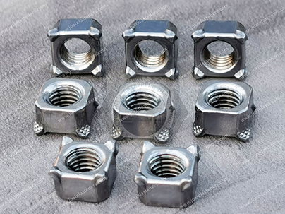
A failed weld nut presents a different problem: the weld attachment itself may have fractured or separated from the parent sheet, leaving the threaded connection unusable even when the nut remains intact.
The repair method therefore needs to consider both the fastener failure mode and the condition of the parent material.
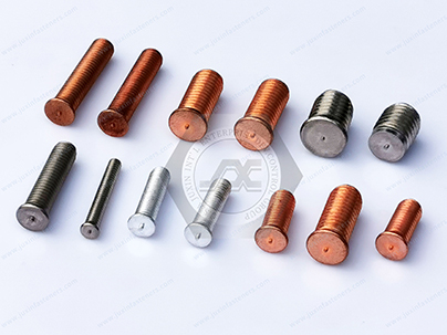 | 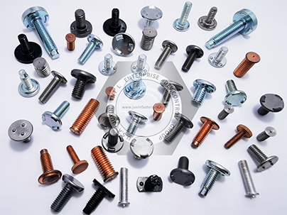 | 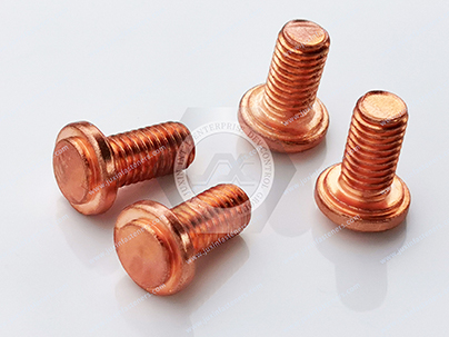 |
At the same time, replacement weld fasteners require appropriate quality inspection.
Mechanical properties, weldability, thread dimensions, coating thickness, coating adhesion, corrosion resistance,
and installation performance should be evaluated against the applicable drawing, product specification, customer requirements, and international test standards.
This technical guide provides plant maintenance engineers, quality assurance professionals, automotive engineers, and procurement teams with a practical engineering framework covering:
Field Extraction Protocols: Controlled extraction methods for broken weld studs, including pilot drilling, localized weld build-up, nut attachment, controlled torsional removal, and thread restoration.
Weld Nut & Weld Fastener Repair: Evaluation of failed weld attachments, parent-sheet condition, replacement options, and post-repair inspection.
Quality Verification Standards: Standardized methods for coating thickness, coating adhesion, corrosion resistance, and thread inspection according to applicable ISO, ASTM, DIN, and ASME specifications.
Preventive Sourcing Considerations: Material selection, weldability, coating systems, mechanical properties, dimensional control, inspection documentation, and replacement hardware procurement.
The objective is not simply to remove a broken fastener. The objective is to restore the original joint function without introducing a new weakness into the parent structure.
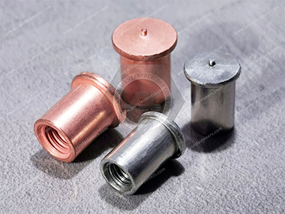 |  |
When a high-strength weld stud shears under installation torque, service loading, vibration, corrosion, or fatigue, the remaining stud section must be removed without unnecessarily damaging the parent structure.
For a conventional threaded fastener that has fractured inside a tapped hole, controlled drilling and extraction may be appropriate.
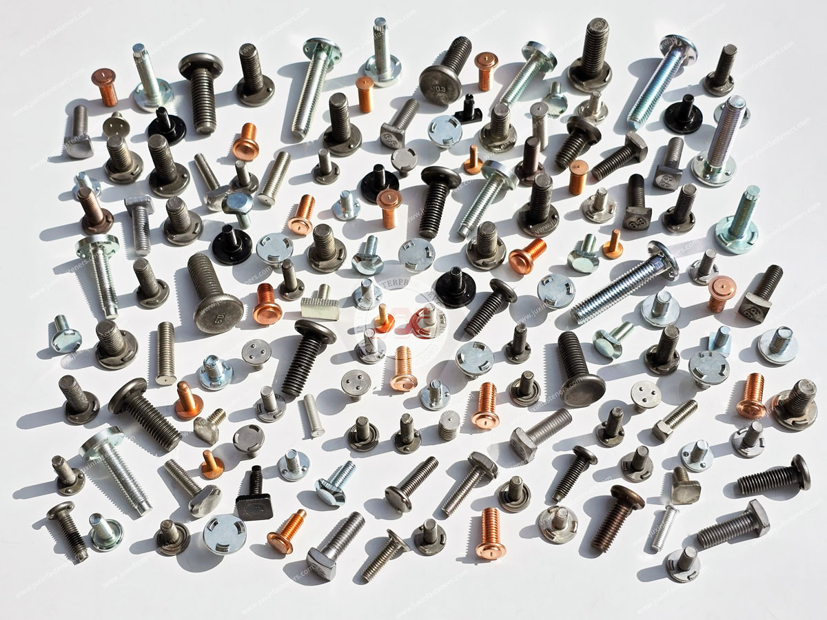
For a welded stud, however, the actual geometry must first be identified because the stud may be attached directly to sheet metal by projection welding, capacitor-discharge (CD) welding, arc welding, or another process.
A commonly used workshop technique for a fractured threaded remnant is localized weld build-up followed by nut attachment.
This method can provide a strong gripping surface while introducing localized heat that may assist removal.
The following sequence is an engineering example rather than a universal repair specification.
Hole diameter, weld build-up dimensions, welding current, electrode selection, nut size,
and extraction torque must be adapted to the actual fastener diameter, material, parent structure, access conditions, and repair procedure.
                      BROKEN WELD STUD EXTRACTION SEQUENCE
  [1. Center Drilling]       [2. Surfacing Weld]        [3. Nut Attachment]      [4. Torsional Removal]
       +-----+                    +-----+                    +-----+                    +-----+
       | | | |                    |***| |                    |###| |                    |     |
       | v | |  ===> Build-up ==>   |***| |  ===> Weld Nut ==> |###| |  ===> Wrench/Tap ==> |(Ext)|
       +-----+                    +-----+                    +-----+                    +-----+
     Pilot Hole / Centering       Weld Build-up             Nut Welded               Controlled Extraction

     Final operation: inspect and restore the original thread / mounting interface
Identify the failure mode before drilling.
Confirm whether the component is a fractured threaded stud, a broken weld stud, a failed weld nut, or a fastener whose threaded section has seized inside the parent component.
This distinction matters because drilling into a welded attachment or sheet-metal panel can cause considerably more damage than drilling into a conventional tapped hole.
Prepare the repair area.
Degrease and remove oil, loose corrosion products, paint, sealant, and other contamination around the fractured area.
For welded assemblies, avoid removing more parent material than necessary.
If the component is part of a structural or safety-critical assembly, the repair procedure should follow the equipment manufacturer's or OEM's approved maintenance procedure where available.
Locate the center axis.
Accurate centering is critical. An off-center pilot hole can damage the original thread or enlarge the parent hole.
A center punch, carbide center tool, or suitable drilling guide can be used where appropriate.
Pilot drilling.
A cobalt or other application-appropriate drill can be used to create a pilot hole through the fractured fastener remnant.
The original GEMINI procedure proposed a 6–8 mm pilot hole. This should be treated as an example for a sufficiently large fastener rather than a universal dimension.
For smaller fasteners, a significantly smaller drill may be required.
Progressive drilling.
If additional material must be removed, enlarge the opening progressively rather than immediately using a large drill.
The original procedure proposed approximately a 16 mm final drill diameter before weld build-up.
This may be appropriate only for sufficiently large fractured fasteners and must be matched to the actual remnant and parent structure.
The primary objective is to remove enough damaged material to create a stable repair surface while preserving the surrounding parent material.
Welding material selection.
Where the repair method uses weld build-up, the filler metal and welding process should be compatible with the fastener and parent material.
Low-hydrogen consumables may be appropriate for certain carbon and alloy steel repair applications,
but the exact electrode or filler specification should be selected according to the material, welding procedure, thickness, preheat requirements, and applicable welding code.
Controlled heat input.
Use controlled welding parameters rather than assuming one current or electrode size works for every fastener.
The original procedure proposed a low-hydrogen rod of ≤3.2 mm diameter with low-to-medium current.
This can remain an example for suitable steel repair work, but actual welding parameters should be determined by the repair procedure and material combination.
Build-up geometry.
The original procedure proposed creating a cylindrical extension approximately 14–16 mm in diameter and 8–10 mm high.
These dimensions should be understood as an example for a sufficiently large fractured stud.
The build-up must provide enough cross-sectional area for wrench engagement without transferring excessive heat into the surrounding parent sheet.
Avoid excessive heat input.
Excessive heat can:
For automotive and industrial assemblies, the repair technician should also consider whether the parent component contains heat-sensitive coatings,
adhesives, sealants, electronics, or previously heat-treated structural material.
Distort thin sheet metal
Damage nearby coatings
Alter heat-treated material properties
Increase the heat-affected zone
Damage nearby seals or electrical components
Increase the risk of cracking in susceptible materials
Immediately after weld build-up, localized thermal contraction during cooling can sometimes help break a seized threaded connection.
Controlled mechanical tapping may also help disturb corrosion products or friction interfaces.
The original procedure describes lightly striking the end face with a hand hammer to introduce controlled axial vibration.
This should be performed carefully.
The objective is not to deform the parent structure. Excessive impact can:
Damage thin sheet metal
Distort mounting surfaces
Crack brittle components
Damage nearby welds
Transfer shock into sensitive assemblies
For seized fasteners, penetrating fluids, controlled heating, induction heating, or other approved extraction techniques may sometimes be more appropriate than impact alone.
Once a stable weld build-up has been created:
Select a nut with sufficient engagement area for the built-up section.
The original procedure specifies a standard M18 heavy hex nut. This should be treated as an example rather than a universal repair size.
The nut size should correspond to the diameter of the weld build-up and the torque required to remove the fractured remnant.
Weld the nut securely to the build-up.
Ensure that the weld provides adequate fusion between the nut and the built-up material.
Allow the assembly to cool to a temperature that can be handled safely. The original procedure used below approximately 60°C as a practical hand-warm reference.
Apply controlled torsional force with an appropriate wrench.
If required, use gentle alternating torque rather than an immediate maximum torque application.
Light tapping may be used where appropriate to assist release, but excessive impact should be avoided.
The extraction torque should remain within the mechanical limits of the surrounding parent structure.
If the fastener does not release, increasing torque indefinitely is not a good repair strategy.
At that point, the technician should reassess whether the remnant is seized by corrosion, galling, thread deformation, cross-threading, or mechanical interference.
After removing the fractured fastener:
Inspect the original internal thread.
Remove corrosion products and weld spatter.
Clean the hole.
Verify the thread profile with the appropriate gauge or inspection tool.
Use a matched machine tap only when thread restoration is permitted by the engineering repair procedure.
Avoid removing excessive parent material simply to make a damaged thread fit.
If the original thread is no longer within specification, options may include:
Thread insert installation
Oversize threaded repair
Replacement of the mounting component
Welding and re-machining where structurally acceptable
Replacement of the weld nut or weld fastener assembly
The repair decision should be based on the required load capacity and the remaining parent material, not simply on whether a replacement bolt can be threaded into the hole.
Broken weld studs and failed weld nuts require different repair approaches.
A weld nut may remain mechanically intact while its welded attachment to the sheet metal has fractured. In this situation, drilling into the nut may be unnecessary and potentially harmful.
The inspection sequence should include:
Inspect the parent sheet around the weld nut.
Check whether the weld nuggets or projections have fractured.
Inspect for sheet tearing or local deformation.
Check the internal thread with the appropriate thread gauge.
Determine whether the nut itself is reusable.
Evaluate whether the original attachment location remains dimensionally correct.
Select an appropriate replacement weld nut if required.
Verify weld compatibility with the parent sheet material and thickness.
Perform post-installation inspection.
For automotive sheet-metal applications, the replacement weld nut should match:
Thread size
Thread pitch
Nut geometry
Projection geometry
Material
Coating
Sheet thickness
Welding process
Required weld strength
OEM drawing requirements
Where corrosion protection is important, the effect of welding on the original coating must also be considered.
Weld areas may require an approved post-weld corrosion-protection process.
Ensuring that replacement weld fasteners and newly manufactured components comply with engineering specifications requires multi-stage quality control.
The inspection method should be selected according to the coating type, substrate material, fastener geometry, thread specification, and customer drawing.
+---------------------------------------------------------------------------------------------------+
|                                  FASTENER QUALITY INSPECTION MATRIX                               |
+--------------------------+---------------------------------+--------------------------------------+
| Inspection Category      | Standard Test Method            | Governing International Standard     |
+--------------------------+---------------------------------+--------------------------------------+
| Coating Thickness        | Magnetic / Eddy Current /       | ISO 2178, ISO 2360, ASTM B499        |
|                          | Metallographic / Coulometric    | Applicable method for coating system |
+--------------------------+---------------------------------+--------------------------------------+
| Coating Adhesion         | File / Bend / Thermal Shock /  | ISO 2819, ASTM B571                  |
|                          | Other Applicable Methods        |                                      |
+--------------------------+---------------------------------+--------------------------------------+
| Corrosion Resistance     | Neutral Salt Spray (NSS)        | ISO 9227, ASTM B117                  |
+--------------------------+---------------------------------+--------------------------------------+
| Thread Tolerance         | Go / No-Go Gauges               | ISO 965-2, applicable thread system  |
+--------------------------+---------------------------------+--------------------------------------+
| Mechanical Properties   | Tensile / Proof Load / Hardness | Applicable product specification    |
+--------------------------+---------------------------------+--------------------------------------+
| Weld Attachment Quality | Weld Integrity / Pull / Torque  | Customer / OEM / Process Specification|
+--------------------------+---------------------------------+--------------------------------------+
ISO 2178 and ASTM B499 provide magnetic methods for measuring the thickness of non-magnetic coatings on magnetic substrates.
For zinc or zinc-alloy coatings over carbon or alloy steel fasteners, magnetic thickness measurement can be an efficient non-destructive production inspection method.
The measurement system should be calibrated against appropriate reference standards and used on representative surfaces.
ISO 2360 applies to non-conductive coatings on non-ferromagnetic electrically conductive substrates and other configurations covered by the standard.
Therefore, it should not simply be listed as an interchangeable method for measuring every zinc coating on steel fasteners.
The correct thickness method depends on the coating/substrate combination.
For high-accuracy verification or dispute resolution, the fastener can be sectioned, mounted in resin, polished, and examined under a calibrated microscope.
Cross-sectional measurement can provide information about:
Coating thickness
Layer structure
Interface quality
Multi-layer coating systems
Local coating defects
This method is destructive, so it is generally used for laboratory verification, process validation, failure analysis, or sampling rather than every-piece production inspection.
Coulometric methods remove a controlled area of coating electrochemically and determine coating thickness from the measured dissolution process.
The applicable coulometric standard should match the coating and substrate system.
This method can be useful when conventional magnetic or eddy-current measurement is unsuitable or when localized coating analysis is required.
Coating adhesion should be evaluated according to the coating system and applicable specification.
ASTM B571 provides methods for evaluating the adhesion of metallic coatings, with test methods selected according to the coating/substrate combination.
ISO 2819 provides methods for adhesion testing of electrodeposited and related metallic coatings on metallic substrates.
Possible evaluation techniques include:
File testing
Bending
Thermal shock
Impact or deformation testing
Other method-specific procedures
The purpose is to determine whether the coating remains adequately bonded to the substrate during the mechanical or thermal conditions represented by the selected test.
Flaking or separation can indicate problems involving:
Surface preparation
Cleaning
Activation
Plating process
Coating structure
Substrate condition
Excessive deformation
Neutral salt spray testing is commonly used for comparative corrosion evaluation of metallic coatings and finished components.
ASTM B117 and ISO 9227 define salt-spray test procedures.
Typical neutral salt spray conditions include a controlled sodium chloride solution and chamber temperature around 35°C,
but the exact test setup, specimen preparation, evaluation criteria, and reporting method must follow the applicable standard.
The purpose is not to claim that a coating is universally "corrosion proof."
Salt spray results should be interpreted as part of a defined coating qualification or comparison program.
For example, an automotive customer may specify a requirement such as:
Hours to first red rust
Hours to white corrosion product
No base-metal corrosion before a specified exposure time
Coating appearance after exposure
Specific test orientation and specimen preparation
A value such as 720 hours, 1,000 hours, or 1,500 hours should therefore only be stated when it is an actual customer requirement or a verified qualification result for the exact coating system.
Salt-spray hours should never be presented as an inherent property of a generic "zinc-nickel finish."
Thread accuracy is critical for replacement weld fasteners because a coating or manufacturing deviation can affect assembly torque, engagement, and final clamping force.
Inspection may include:
GO / NO-GO gauges
Thread ring gauges
Thread plug gauges
Pitch diameter measurement
Major diameter measurement
Minor diameter measurement
Optical measurement
Coordinate measurement where appropriate
For ISO metric threads, ISO 965 provides tolerance principles and limits for metric screw threads. The exact tolerance class must be specified according to the drawing.
For automotive weld nuts and studs, the inspection program should also consider:
Nut height
Flange diameter
Projection dimensions
Stud length
Stud diameter
Concentricity
Perpendicularity
Weld projection geometry
Head dimensions
Thread runout
Coating coverage
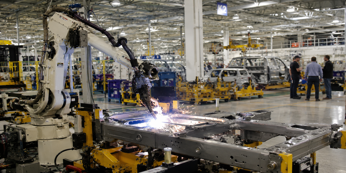
A weld fastener is not only a threaded component. It is also a welded structural interface.
Therefore, quality verification may include:
Tensile testing
Proof load testing
Torque testing
Torque-out testing
Push-out testing
Pull-off testing
Weld integrity evaluation
Dimensional inspection
Visual inspection
Metallographic examination
Process capability monitoring
The appropriate test depends on whether the product is a weld nut, projection weld stud, CD weld stud, arc weld stud, or another welded fastening component.
For production automotive programs, the acceptance criteria should come from the customer's engineering drawing, weld process specification, control plan,
or validation procedure rather than using one universal pull-out or torque value.
When procuring replacement weld fasteners or specifying components for high-reliability assemblies, design engineers and procurement teams should evaluate the complete fastening system.
Ensure suppliers can provide appropriate material and batch documentation when required.
Depending on the fastener specification, documentation may include:
Material certificates
Chemical composition
Mechanical properties
Heat-treatment records
Coating certificates
Dimensional inspection reports
Batch / lot traceability
Production inspection records
The original specification proposed a carbon-content limit of C ≤ 0.15% for weld studs and nuts to guarantee clean, spatter-free resistance welding.
This should not be treated as a universal requirement.
Weldability depends on the actual material grade, carbon equivalent, alloying elements, sheet thickness, fastener geometry, welding process, current, electrode condition, coating, and process control.
For resistance-welded automotive fasteners, the material should therefore be specified by the applicable product drawing and welding validation procedure rather than by carbon content alone.
Surface treatment must be selected according to both corrosion requirements and assembly requirements.
Potential systems include:
Zinc electroplating
Zinc-nickel plating
Zinc-flake coating
Organic topcoats
Stainless steel
Other application-specific corrosion-protection systems
For high-strength steel fasteners, electroplating processes require appropriate hydrogen-embrittlement risk controls.
ISO 10683 covers non-electrolytically applied zinc-flake coating systems for steel fasteners and is particularly relevant to high-strength fasteners where internal hydrogen embrittlement is a concern.
However, zinc-flake coating should not automatically be treated as the correct coating for every weld fastener.
The coating selection should consider:
Fastener strength class
Welding process
Welding location
Corrosion environment
Required friction coefficient
Assembly torque
Electrical conductivity requirements
Coating thickness
Post-weld corrosion protection
Temperature exposure
Customer specifications
For procurement teams replacing a failed weld fastener, the RFQ should ideally define:
Fastener type
Thread size
Thread pitch
Fastener length
Head or flange geometry
Projection geometry
Material
Mechanical property class
Coating
Coating thickness
Corrosion requirement
Welding process
Parent sheet material
Parent sheet thickness
Weld strength requirement
Thread tolerance
Dimensional tolerances
Inspection requirements
Packaging requirements
Lot traceability
Applicable customer / OEM specification
Understanding the original failure mechanism is essential before selecting a replacement.
A broken weld stud does not necessarily mean that the fastener material was simply "too weak."
Potential failure mechanisms include:
Excessive installation torque can exceed the tensile or torsional capacity of the fastener.
This can occur when:
Thread friction is too low
Coating friction changes
Assembly tooling is incorrectly calibrated
Thread damage increases installation resistance
Incorrect fastener grade is installed
Repeated cyclic loading can initiate cracks at stress-concentration locations such as:
Thread roots
Undercuts
Fillets
Weld interfaces
Surface defects
A fastener can therefore fail under loads significantly below its ultimate tensile strength when the stress is repeated over a large number of cycles.
For projection weld studs and weld nuts, the threaded component may remain intact while the welded interface fails.
Possible causes include:
Insufficient weld energy
Incorrect current
Electrode wear
Poor surface preparation
Excessive coating at the weld interface
Incorrect projection geometry
Parent sheet deformation
Insufficient weld area
Material incompatibility
Excessive service loading
Corrosion can reduce the effective cross-sectional area of a fastener and introduce localized stress concentrations.
For automotive applications, particular attention should be given to:
Road salt
Humidity
Condensation
Battery enclosure environments
Underbody exposure
Dissimilar-metal interfaces
The corrosion-protection system must therefore be selected according to the actual environment rather than simply choosing the highest nominal salt-spray number.
Thread damage can increase assembly torque and produce false torque readings.
Potential causes include:
Cross-threading
Incorrect thread pitch
Contamination
Burrs
Coating buildup
Stainless-steel galling
Misalignment
For critical assemblies, thread inspection and controlled assembly torque should be part of the production quality system.
Weld fasteners are widely used where a permanent threaded attachment point is required on sheet metal or structural components.
Typical applications include:
Door structures
Hood structures
Seat brackets
Instrument panel supports
Underbody components
Exhaust shields
Wiring brackets
Electronic control unit mounts
Battery tray brackets
Battery cover attachments
Cooling-system brackets
Electrical grounding points
Cable and harness supports
Thermal management components
Internal module mounting points
Chassis brackets
Hydraulic equipment
Cab structures
Engine components
Protective covers
Electrical cabinets
Service panels
Machine guards
Control panels
Motor housings
Automation equipment
Sheet-metal frames
HVAC equipment
Electrical enclosures
Explore the JUXIN FASTENERS technical reference library for complete engineering solutions across weld fasteners, automotive fasteners, threaded inserts, and high-strength fastening systems:
Precision Projection Weld Studs & Sheet Metal Fastening Guide
https://www.juxinfasteners.com/industrial-solutions/projection-weld-studs-sheet-metal-fastening-guide/
Advanced projection weld stud design, sheet-metal fastening mechanics, welding considerations, and industrial applications.
Preventing Bolt Loosening & Fatigue Failure Solutions
https://www.juxinfasteners.com/technical-guide/bolt-loosening-fatigue-failure-prevention-solutions/
Engineering analysis of preload loss, rotational loosening, transverse vibration, fatigue failure, and high-vibration fastening solutions.
EV Automotive Fasteners & Lightweight Joining Solutions
https://www.juxinfasteners.com/automotive-solutions/ev-fasteners-lightweight-joining-ultra-high-strength-bolts/
EV battery fasteners, high-strength automotive bolts, lightweight joining, self-clinching hardware, and aluminum-steel fastening considerations.
Threaded Inserts for Plastics: Engineering Installation Guide
https://www.juxinfasteners.com/industrial-solutions/thread-insert-nuts-engineering-installation-guide/
Post-mold threaded insert selection, plastic boss design, installation methods, and automotive electronic housing applications.
Precision Knurled Brass Threaded Inserts: After-Molding Installation Guide
https://www.juxinfasteners.com/industrial-solutions/knurled-brass-inserts-after-molding-installation-guide/
Heat-staking, ultrasonic insertion, knurled brass inserts, and post-molding threaded fastening for engineered plastics.
Automotive Wheel Fasteners & Lightweight Aluminum Joinery Guide
https://www.juxinfasteners.com/automotive-solutions/wheel-hub-bolts-nuts-aluminum-body-fasteners/
Automotive wheel fasteners, aluminum structures, lightweight joining technologies, and related fastening solutions.
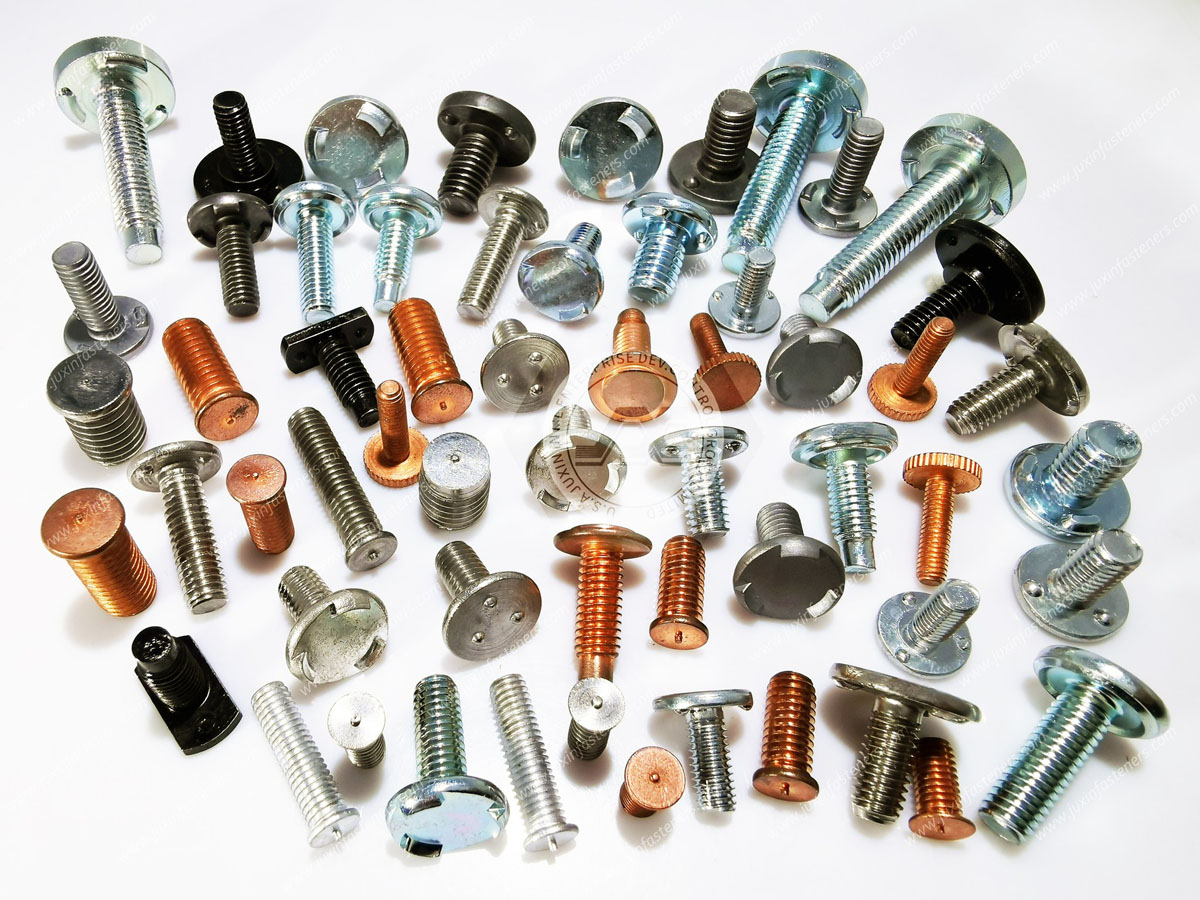
JUXIN FASTENERS manufactures and supplies weld nuts, projection weld studs, CD weld fasteners, arc weld pins, and custom cold-formed industrial fastening components for automotive and industrial applications.
Our manufacturing capabilities include cold heading, precision forming, thread rolling, CNC machining, inspection, and application-specific surface treatment.
For replacement and new-production weld fasteners, JUXIN FASTENERS can support requirements involving:
Projection weld studs
Projection weld nuts
CD weld studs
Arc weld studs
Automotive weld studs
Automotive weld nuts
Battery enclosure weld fasteners
Sheet-metal fastening components
Custom threaded weld fasteners
High-strength automotive fasteners
Custom cold-formed fasteners
Precision CNC-machined components
Engineering and sourcing discussions can include:
Fastener drawing review
Material selection
Thread specification
Weld geometry
Parent-sheet compatibility
Coating selection
Corrosion requirements
Dimensional inspection
Mechanical testing requirements
Samples
Custom tooling
Production specifications
Quality documentation
Bulk procurement RFQs
For technical data sheets, custom tooling inquiries, replacement fastener development, or bulk procurement RFQs:
Official Website:
https://www.juxinfasteners.com
Technical Sourcing Email:
info@juxinfasteners.com
Product Capabilities:
Projection Weld Studs, Weld Nuts, CD Weld Fasteners, Arc Weld Pins, Automotive Weld Fasteners, Battery Enclosure Weld Fasteners, Custom Cold-Formed Industrial Fasteners.
A broken weld stud or failed weld nut should be treated as a joint-system failure investigation, not simply as a damaged piece of hardware.
Successful repair requires three separate decisions:
1. Extract the failed component without unnecessarily damaging the parent structure.
2. Verify the repaired interface and replacement fastener against the correct dimensional, mechanical, coating, corrosion, and welding requirements.
3. Identify the original failure mechanism so that the replacement fastener, coating, weld process, and joint design address the cause rather than simply replacing the failed component.
For automotive, EV battery, heavy equipment, and industrial applications,
the most reliable procurement specification combines fastener material + mechanical class + thread geometry + weld configuration + coating system + inspection method + application environment.
That complete specification is the foundation for consistent weld fastener performance and repeatable industrial production.
 MORE NEWS

Sep. 25, 2026

Sep. 25, 2026

Sep. 25, 2026
Contact Us
Tel.:
+86 020 8621 0320
+86 020 3121 6067
E-mail:
Technical Support:
Navigation
SEND INQUIREY