Call Us
+86 136 6007 9809
Call Us
+86 136 6007 9809

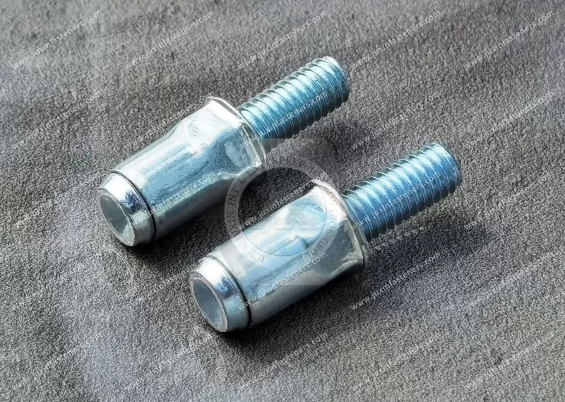
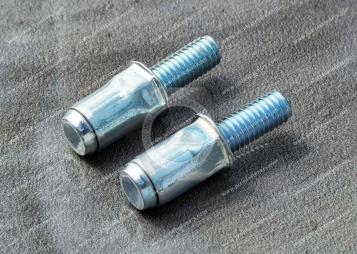
JUXIN FASTENERS supplies steel thin head partial hexagonal body blind rivet studs for one-sided installation of external threaded mounting points in sheet-metal assemblies. The reduced-profile head helps limit protrusion above the accessible panel surface, while the partial hexagonal body can resist rotation when installed in a compatible mounting hole. Available in M5, M6 and M8 with a blue-white zinc finish, these studs are suitable for engineering evaluation in equipment enclosures, fabricated brackets and serviceable OEM assemblies.
Thread Sizes: M5, M6, M8
Material: Steel (grade to be confirmed)
Surface Finish: Blue-White Zinc (RoHS compliance subject to verification)
Grip Range: 0.5–5.5 mm (product family; verify by part number)
Head Type: Thin Head / Reduced-Profile Head
Body Type: Partial Hexagonal / Part-Hex
Thread Type: External Male Metric Thread
Installation: One-Sided Mechanical Blind Riveting
Product Specification
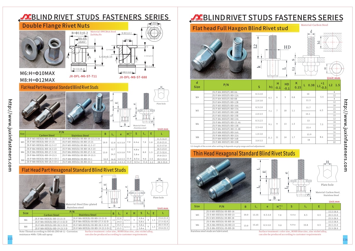
Product Specifications — Steel Thin Head Partial Hexagonal Body Blind Rivet Studs
JUXIN FASTENERS supplies steel thin head partial hexagonal body blind rivet studs with blue-white zinc finish for OEM sheet-metal assemblies requiring externally threaded mounting points, reduced head projection and one-sided mechanical installation.
The thin head helps reduce the amount of fastener head protruding above the accessible panel surface compared with a corresponding conventional flat-head configuration, subject to the actual drawings.
The partial hexagonal body provides a polygonal interface that can engage a compatible mounting hole and contribute to resistance against stud rotation.
The external male thread allows a mating component to be secured using a suitable nut after the rivet stud has been installed.
This product is intended for engineering evaluation where installation access, panel geometry, head clearance and assembly torque must be considered together.
Technical Specification Summary
Product Type: Thin Head Partial Hexagonal Body Blind Rivet Stud
Material: Steel
Steel Grade: Subject to approved specification
Thread Sizes: M5, M6, M8
Thread Configuration: External Male Metric Thread
Head Type: Thin Head / Reduced-Profile Head
Body Configuration: Partial Hexagonal / Part-Hex Body
Surface Treatment: Blue-White Zinc
RoHS Compliance: Subject to verification
Grip Range: 0.5–5.5 mm across the product family
Installation Method: One-Sided Mechanical Blind Riveting
Head Diameter and Thickness: According to approved drawing
Hexagonal Body Dimensions: According to approved drawing
Mounting-Hole Dimensions: According to approved drawing
External Stud Projection: According to approved drawing
Installation Parameters: Subject to part and tooling verification
Mechanical Performance: Subject to application-specific validation
Individual M5, M6 and M8 part numbers must be checked for their actual grip ranges and dimensional specifications.
What Is a Thin Head Partial Hexagonal Blind Rivet Stud?
A thin head partial hexagonal blind rivet stud is a mechanically installed fastener that provides an external threaded mounting point in a panel or hollow section where access to the rear surface is limited.
The rivet body is inserted into a prepared mounting hole from the accessible side.
A compatible setting tool deforms the rivet body behind the parent material, creating mechanical retention.
The exposed male thread can then be used to attach a bracket, cover, support or other component using a suitable nut.
The thin head reduces the accessible-side head projection.
The partial hexagonal body provides a geometric interface that can help resist rotation when installed in a compatible mounting hole.
Thin Head vs. Conventional Flat Head
Thin head and flat head blind rivet studs serve similar basic fastening functions, but their head geometries address different assembly constraints.
Thin Head
A reduced-profile head may help limit interference with adjacent components.
It can be useful where the accessible panel surface has restricted clearance.
Flat Head
A conventional flat head may provide a different bearing area and installed projection.
The actual differences depend on the approved dimensions.
Engineering selection should consider:
Head thickness
Head diameter
Available panel clearance
Local bearing conditions
Mating component geometry
Installation deformation
Required installed performance
A thin head does not automatically provide flush installation.
It also should not automatically be described as mechanically equivalent to a thicker head.
The actual head geometry and installed performance must be verified.
Engineering Information Gain — Reduced Head Projection vs. Panel Bearing Area
A thinner head can improve clearance in some sheet-metal assemblies.
However, reducing head thickness or changing head diameter may also affect how the fastener bears against the parent material.
Consider an OEM equipment cover where a mating bracket must sit close to the panel surface.
A thin head may reduce the clearance required around the installed fastener.
However, the engineer should still evaluate:
Head diameter
Local panel strength
Panel thickness
Head seating
Installation deformation
Assembly loading
Installed axial retention
Available mating-component clearance
The lowest-profile head is not automatically the best engineering choice.
The correct design balances head clearance with the required mechanical retention and parent-panel conditions.
Thin Head vs. Countersunk Head
Thin head and countersunk head designs should not be treated as interchangeable.
A thin head reduces head projection through its geometry.
A countersunk head is intended to seat within a compatible prepared recess.
Countersunk installation depends on head angle, head diameter, recess geometry and panel thickness.
A thin head does not necessarily require the same countersinking operation, but its actual mounting-hole requirements must still be confirmed.
For an OEM application, the choice should consider:
Required surface clearance
Head projection
Panel thickness
Hole preparation
Available manufacturing process
Installed mechanical performance
Assembly cost
Where true flush mounting is required, the engineer should evaluate the complete head and panel geometry rather than relying on the term thin head.
Partial Hexagonal Body and Anti-Rotation Function
The partial hexagonal body incorporates a polygonal section intended to engage a compatible mounting hole.
When a mating nut is tightened onto the external thread, torque may be transmitted to the installed stud.
The polygonal interface can help resist rotation through geometric engagement with the parent material.
Actual rotational resistance depends on:
Hexagonal section dimensions
Mounting-hole geometry
Parent-material properties
Panel thickness
Hole-manufacturing tolerance
Rivet-body deformation
Installation-tool settings
Applied assembly torque
No universal spin-out torque rating is claimed.
The installed performance should be verified for the actual assembly.
Partial Hex vs. Full Hex vs. Knurled Body
Partial Hexagonal Body
Provides a polygonal section over part of the relevant body length.
The section can engage a corresponding mounting hole.
Full Hexagonal Body
Provides a more extensive polygonal exterior according to its design.
The actual installation behavior depends on body geometry and deformation characteristics.
Knurled Body
Uses raised exterior features that may engage the parent material.
The required mounting-hole geometry and installed performance may differ.
These configurations should be compared using actual product drawings and application testing.
No body type should automatically be described as mechanically superior without comparable evidence.
Mounting-Hole Geometry for Partial Hex Studs
Where anti-rotation depends on polygonal engagement, the mounting hole must provide compatible geometry.
Important dimensions include:
Across-flats dimension
Across-corners clearance
Corner geometry
Hole tolerance
Hole position
Parent-material thickness
Edge distance
Burr condition
Local panel deformation
An oversized hole may reduce the intended engagement.
An undersized hole may prevent insertion or damage the fastener or panel.
The actual hole specification must be confirmed from the approved part drawing.
Engineering Information Gain — Head Clearance and Hole Geometry Must Be Designed Together
A thin head partial hexagonal rivet stud introduces two separate geometric requirements.
The head must fit within the available accessible-side clearance.
The partial hexagonal body must fit and engage the prepared mounting hole.
An assembly may satisfy one requirement but fail the other.
For example, a stud may have a sufficiently thin head but require a mounting hole that the existing production tooling cannot create accurately.
Alternatively, the mounting hole may be compatible while the head projection interferes with the mating bracket.
An OEM design review should therefore evaluate head geometry, body geometry and mating-component clearance as one assembly.
This can help avoid late-stage tooling changes or supplier substitution problems.
Blind Rivet Stud Installation Principle
Blind rivet threaded studs use a mechanical setting principle similar to blind rivet nuts.
The difference is the external male thread.
For a blind rivet nut, the setting tool generally engages an internal female thread using a compatible threaded mandrel.
For a blind rivet stud, the tool must engage the external male thread.
A compatible internally threaded setting sleeve may be used instead of the threaded mandrel arrangement used for a blind rivet nut.
The setting tool applies the required stroke or mechanical action to deform the rivet body behind the parent panel.
This creates the retaining feature that holds the stud in place.
The exact tool configuration, sleeve dimensions and setting parameters must be verified for the selected stud.
Internally Threaded Setting Sleeve Compatibility
The setting sleeve is an important component of the installation system.
It must engage the external male thread correctly and transmit the required setting action.
Relevant considerations include:
Thread size
Thread pitch
Thread engagement
Sleeve geometry
Tool compatibility
Setting stroke
Alignment
Risk of thread damage
Release after installation
An M5, M6 or M8 designation alone does not establish compatibility with every setting tool.
The actual sleeve and equipment requirements should be confirmed with the selected installation system.
One-Sided Installation Procedure
A typical installation sequence includes:
Prepare the mounting hole according to the approved drawing.
Inspect the polygonal hole geometry and edge condition.
Verify the parent-panel thickness.
Confirm the selected stud's grip range.
Fit the compatible internally threaded setting sleeve.
Engage the external male thread correctly.
Align the partial hexagonal body with the mounting hole.
Insert the rivet body from the accessible side.
Seat the thin head against the panel surface.
Apply the approved setting stroke or mechanical action.
Deform the rivet body behind the parent material.
Release the installation equipment.
Inspect head seating, alignment and installed retention.
The actual setting process must follow the selected product and tooling specifications.
Grip Range — 0.5–5.5 mm
The confirmed product-family grip range is 0.5–5.5 mm.
Approximate inch references:
0.5 mm = 0.020 in
5.5 mm = 0.217 in
Grip range refers to the parent-material thickness that the selected rivet body is designed to accommodate during installation.
It is not equivalent to external stud length.
Individual M5, M6 and M8 variants may have different permitted grip ranges.
The actual part-number specification must be verified.
Incorrect grip selection may result in incomplete deformation, poor head seating, insufficient retention or excessive panel distortion.
Metric Thread Sizes and Inch References
The confirmed thread sizes are M5, M6 and M8.
M5: Approximately 0.197 in nominal diameter
M6: Approximately 0.236 in nominal diameter
M8: Approximately 0.315 in nominal diameter
These are approximate dimensional references only.
They are not equivalent UNC, UNF or BSW thread sizes.
Metric and Unified inch threads are not directly interchangeable.
ISO 261 and ISO 965 provide relevant references for ISO metric thread combinations and tolerances where specified.
Actual thread pitch and tolerance must be confirmed from the approved drawing.
Steel Material and Formability
The confirmed base material is steel.
The exact grade, hardness and material condition have not been supplied.
The material must be suitable for the external threaded function and the required rivet-body deformation.
Engineering considerations include:
Steel grade
Material condition
Formability
Thread requirements
Rivet-body geometry
Installation deformation
Coating compatibility
Parent-material properties
A change in material grade may affect installation behavior even when the nominal dimensions remain unchanged.
Blue-White Zinc Surface Treatment
The specified surface treatment is blue-white zinc.
This is a commercial appearance designation and does not independently define the complete coating system.
An OEM coating specification should identify:
Zinc coating type
Coating thickness
Conversion coating
Supplemental treatment
Surface appearance
Corrosion requirements
Thread compatibility
Restricted-substance requirements
Inspection documentation
Blue-white zinc appearance alone does not establish corrosion performance or RoHS compliance.
Appropriate supporting documentation should be reviewed where compliance is required.
ISO 4042 and Coating Requirements
ISO 4042 provides an international technical framework for electroplated coating systems on steel fasteners.
Where applicable, relevant requirements include coating designation, coating thickness, dimensional compatibility, corrosion protection and hydrogen embrittlement risk management.
The approved customer specification should determine which requirements apply.
Reference to ISO 4042 does not establish a specific coating certification or test result for this product.
Corrosion Resistance and Environmental Selection
Zinc coatings are commonly used to provide corrosion protection to steel fasteners.
Actual performance depends on the complete coating system and service environment.
Relevant factors include:
Coating thickness
Conversion coating
Supplemental treatment
Moisture exposure
Salt exposure
Mechanical damage
Dissimilar-metal contact
Storage conditions
Where corrosion testing is specified, ISO 9227 or ASTM B117 may provide relevant test methods.
The required exposure duration and acceptance criteria must be defined separately.
No specific salt-spray rating or outdoor service life is claimed.
Hydrogen Embrittlement Considerations
Certain electroplating processes can introduce hydrogen into steel components.
For susceptible materials, hydrogen may contribute to delayed cracking under specific conditions.
The relevance depends on steel strength, hardness, manufacturing history, coating process and applied stress.
Because the exact steel grade and hardness are not confirmed, no product-specific hydrogen embrittlement classification is claimed.
Where applicable, the approved material and coating specifications should address relevant controls.
Installed Axial Retention
Axial retention describes resistance to extraction of the installed stud from the parent material.
Performance depends on:
Rivet-body geometry
Grip thickness
Parent-material strength
Hole dimensions
Installation deformation
Head seating
Material condition
A thin head may introduce different local bearing conditions from a conventional flat head.
The installed performance should therefore be validated for the selected configuration.
No universal axial pull-out rating is claimed.
Rotational Resistance and Assembly Torque
The partial hexagonal section can help resist stud rotation when a mating nut is tightened or removed.
The required rotational resistance depends on the intended assembly torque and service conditions.
Relevant factors include:
Mounting-hole engagement
Parent-material properties
Installation quality
Thread condition
Mating nut type
Applied assembly torque
No universal spin-out torque rating is claimed.
The assembly should be qualified according to the actual load and installation requirements.
Anti-Rotation vs. Nut Loosening
The partial hexagonal body can contribute to resistance against rotation of the installed stud.
This does not independently prevent the mating nut from loosening.
Stud Anti-Rotation
Concerns rotation of the installed rivet stud within the mounting hole.
Nut Loosening Resistance
Concerns maintaining the required threaded-joint condition during service.
Where vibration resistance is required, the complete nut-and-stud connection should incorporate an appropriate locking strategy and application-specific validation.
Engineering Example — Low-Clearance Equipment Panel
Consider an OEM equipment panel requiring an M6 external threaded mounting point.
The rear side of the panel is inaccessible after fabrication.
The mating component must sit close to the accessible panel surface.
A thin head partial hexagonal blind rivet stud may be evaluated for this application.
The engineering team should confirm:
Required M6 thread pitch and tolerance
Parent-panel material
Panel thickness
Approved grip range
Thin-head diameter and thickness
Available head clearance
Partial hexagonal body dimensions
Mounting-hole geometry
Installed stud projection
Mating component thickness
Required nut engagement
Assembly torque
Setting sleeve compatibility
Installed axial retention
Installed rotational resistance
Coating specification
Corrosion requirements
The reduced-profile head alone does not establish suitability.
The complete assembly geometry must be evaluated.
Industrial Applications
Industrial Machinery
Potential uses include equipment covers, mounting brackets, guards and serviceable components with restricted head clearance.
Electrical Cabinets and Control Enclosures
Possible applications include internal mounting supports, accessory brackets and fabricated housings.
HVAC Equipment
Potential applications include sheet-metal housings, equipment brackets and mounting supports.
Automotive Equipment and Tier 1 Assemblies
The studs may be evaluated for selected non-safety-critical brackets, fabricated panels and equipment housings.
Automotive use requires project-specific engineering and customer approval.
Commercial Vehicle Equipment
Potential applications include selected non-critical equipment mounting points and fabricated metal components.
Fabricated Metal Products
Other possible applications include industrial cabinets, hollow metal profiles, modular sheet-metal assemblies and equipment frames.
The final selection must reflect the actual service environment and mechanical requirements.
OEM Supplier Qualification
Purchasing and supplier development teams should verify:
Product Identity
Confirm thin head, partial hexagonal body and external male metric thread.
Material
Verify the required steel grade and material condition.
Head Geometry
Confirm head thickness and diameter.
Body Geometry
Compare partial hexagonal dimensions and grip range.
Mounting-Hole Compatibility
Confirm the required polygonal hole dimensions.
Coating
Define the actual blue-white zinc coating system.
Installation
Review internally threaded setting sleeve compatibility and tool parameters.
Mechanical Performance
Determine whether axial retention and rotational resistance testing is required.
Documentation
Define inspection records, traceability and drawing revision requirements.
Commercial Terms
Confirm order quantity, annual demand, delivery expectations and packaging instructions.
Information Gain — Why a Thin Head Stud May Not Be a Direct Flat Head Replacement
An OEM purchasing team may identify a thin head partial hexagonal rivet stud with the same M6 thread as an existing flat head product.
However, the two products should not automatically be considered interchangeable.
The thin head may change the accessible-side bearing geometry.
The body length or grip range may differ.
The partial hexagonal section may require a different mounting hole.
The installed stud projection may change.
The setting sleeve or installation stroke may differ.
The installed axial retention and rotational resistance may require separate validation.
A replacement should therefore be reviewed against the complete assembly drawing and qualification requirements.
This can help avoid tooling changes, assembly interference and unexpected production costs.
Engineering Change Control
For established OEM programs, changes to the fastener should be reviewed according to customer requirements.
Potential controlled characteristics include:
Steel grade
Material condition
Head thickness
Head diameter
Partial hexagonal dimensions
Grip range
External thread dimensions
Surface coating system
Installation process
Inspection requirements
Where a change affects fit, function or approved specifications, additional review or validation may be required.
Drawing-Based OEM and Custom Requirements
Some applications require special dimensions or performance characteristics.
Potential drawing-based requirements include:
Customer-defined thin-head thickness
Special head diameter
Partial hexagonal across-flats dimensions
Modified hexagonal section length
Application-specific grip range
Defined steel grade
External stud projection
Controlled metric thread tolerance
Customer-specified zinc coating
Inspection documentation
Packaging and traceability requirements
Nonstandard requirements are subject to technical review and manufacturing feasibility confirmation.
Frequently Asked Questions
What is a thin head partial hexagonal blind rivet stud?
It is a mechanically installed fastener with an external male thread, reduced-profile head and partially hexagonal body, intended for one-sided installation.
What is the difference between thin head and flat head?
A thin head is designed with reduced head projection compared with a corresponding conventional flat-head configuration, subject to actual dimensions.
Does a thin head provide flush mounting?
Not automatically. Actual head projection and assembly clearance must be verified.
What thread sizes are available?
The confirmed sizes are M5, M6 and M8.
What is the grip range?
The supplied product-family range is 0.5–5.5 mm. Individual part-number ranges require confirmation.
Why use a partial hexagonal body?
The polygonal section can engage a compatible mounting hole and contribute to resistance against stud rotation.
How are blind rivet studs installed?
They use a mechanical setting process similar to blind rivet nuts, but the external male thread requires compatible tooling, such as an internally threaded setting sleeve.
Is blue-white zinc automatically RoHS compliant?
No. Compliance must be verified using appropriate documentation for the actual coating system.
Can thin head rivet studs replace flat head versions?
Not automatically. Head geometry, mounting-hole compatibility, grip range and installed performance must be reviewed.
Related Industrial Fastening Solutions
Engineers and procurement teams evaluating thin head partial hexagonal blind rivet studs may also consider these related product categories.
Flat Head Partial Hexagonal Blind Rivet Studs — for applications where conventional head geometry is suitable.
Stainless Steel Partial Hexagonal Blind Rivet Studs — for applications requiring a different material system.
Smooth Round Body Blind Rivet Studs — for cylindrical body configurations.
Knurled Body Blind Rivet Studs — for alternative body engagement characteristics.
Countersunk Blind Rivet Studs — for recessed head installation requirements.
Blind Rivet Nuts — for one-sided assemblies requiring internal female threads.
Self-Clinching Studs — for suitable press-installed sheet-metal applications.
Weld Studs — for applications designed around an approved welding process.
These are contextual internal-link anchor texts. Each should be linked only to a verified relevant product page.
OEM RFQ Checklist
For accurate quotation and technical review, please provide the following information where available:
Required thread size: M5, M6 or M8
Engineering drawing or CAD file
Thread pitch and tolerance
Required steel grade
Thin-head diameter and thickness
Partial hexagonal across-flats dimension
Hexagonal section length
External stud projection
Parent-panel material
Panel thickness
Required grip range
Mounting-hole dimensions and tolerance
Installation equipment and setting sleeve requirements
Blue-white zinc coating specification
RoHS or corrosion documentation requirements
Required axial retention
Required rotational resistance
Inspection and traceability requirements
Initial order quantity
Estimated annual demand
Packaging and delivery requirements
Providing the approved drawing and installation conditions helps establish compatibility and accurate quotation requirements.
JUXIN FASTENERS — OEM Thin Head Blind Rivet Stud Supply
JUXIN FASTENERS supplies industrial fastening products for international OEM engineering, procurement and supplier development requirements.
Our steel thin head partial hexagonal blind rivet studs with blue-white zinc finish are intended for applications requiring external threaded mounting points, one-sided installation, reduced head projection and geometric resistance to rotation.
For M5, M6 and M8 requirements, customers may submit engineering drawings, coating specifications, installation details and purchasing quantities for technical review.
Request an OEM Technical Quotation
Email: info@juxinfasteners.com
Website: www.juxinfasteners.com
Please include your product drawing, required quantity, steel specification, panel thickness, mounting-hole dimensions, head clearance and coating requirements.
JUXIN FASTENERS — Industrial Fastening Solutions for OEM Engineering and Global Procurement.
Product Packaging
Product Packaging — Steel Thin Head Partial Hex Blind Rivet Studs
Packaging for M5, M6 and M8 steel thin head partial hexagonal blind rivet studs with blue-white zinc finish is subject to confirmed order and customer requirements.
Protective Packaging: Suitable protective arrangements may be specified to help reduce damage to external male threads, thin-head seating surfaces, partial hexagonal body geometry and zinc-coated surfaces.
Outer Packaging: Carton arrangements may be reviewed according to shipment quantity, weight and handling requirements.
Pallet Packaging: Palletized shipments may be considered for bulk OEM orders, subject to confirmation.
Product Identification: Customer-specified labels may identify the part number, thread size, material, surface finish, quantity, lot number and drawing revision.
Lot Traceability: Identification and traceability requirements should be defined in the approved purchasing and quality documentation.
OEM Packaging: Customer-specific packing quantities, component segregation, labeling and logistics instructions are subject to review.
Final packaging details will be confirmed against the approved order.
For OEM quotations and packaging requirements:
Email: info@juxinfasteners.com
Website: www.juxinfasteners.com
Product Pictures
Tags
Contact Us
Tel.:
+86 020 8621 0320
+86 020 3121 6067
E-mail:
Technical Support:
Navigation
SEND INQUIREY