Call Us
+86 136 6007 9809
Call Us
+86 136 6007 9809

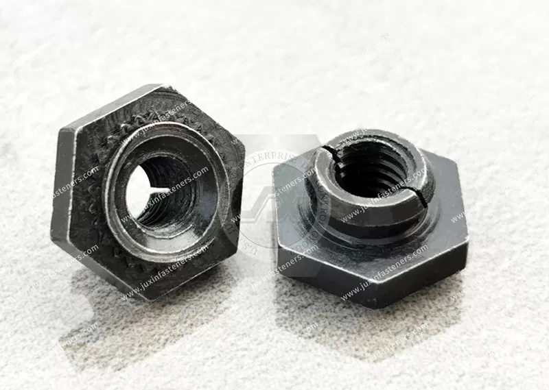
JUXIN FASTENERS supplies all-metal self-locking self-clinching nuts for industrial sheet metal assemblies requiring reusable internal threads with prevailing-torque locking performance.
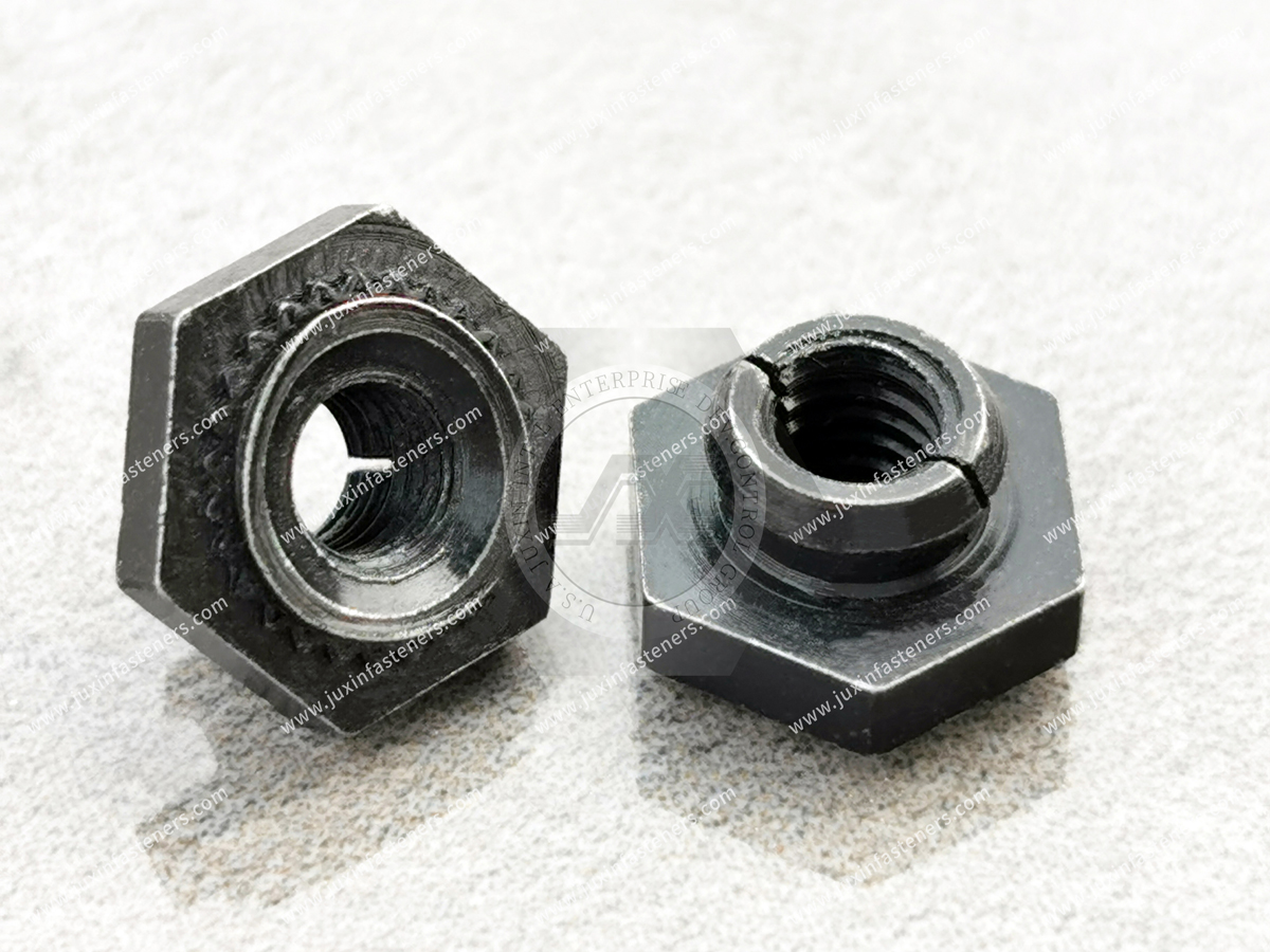
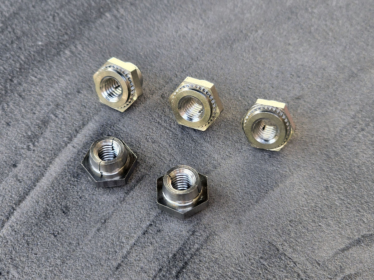
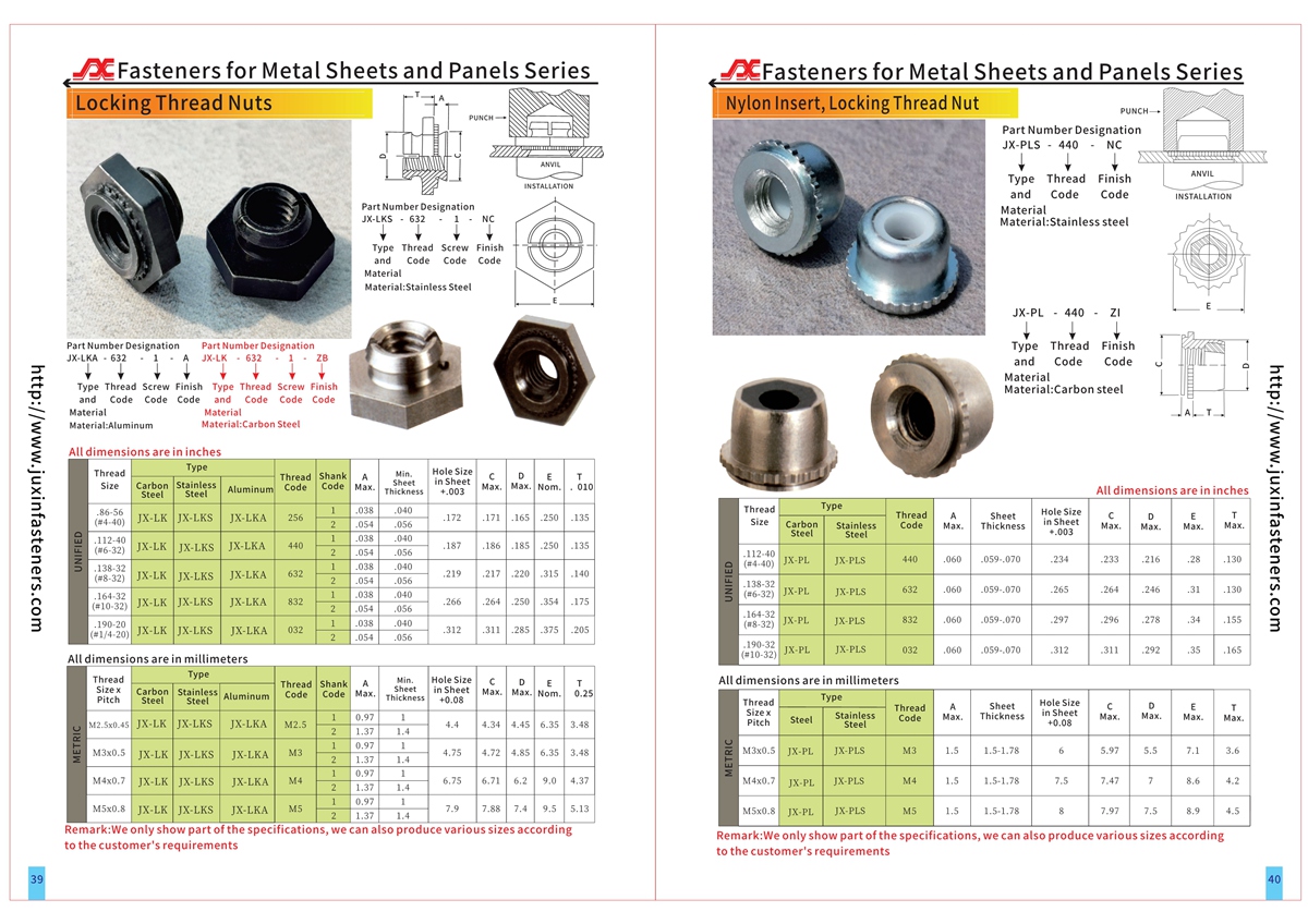
The JX-LK, JX-LKA and JX-LKS series uses a two-jaw flexible locking design that creates resistance to screw rotation without relying on a nylon insert. The self-clinching retention features secure the nut in a compatible metal sheet, while the locking jaws provide a separate thread-locking function.
JX-LK is the steel configuration, JX-LKA is the aluminum configuration, and JX-LKS is the stainless steel configuration. The supplied product family covers selected metric and inch-series thread sizes, subject to model-specific availability.
These fasteners are suitable for evaluation in compact industrial enclosures, electronic equipment, control cabinets and serviceable mechanical assemblies.
For dimensional specifications, installation requirements, material selection and OEM quotations, contact info@juxinfasteners.com.
Website: www.juxinfasteners.com
Product Specification
All-Metal Self-Locking Self-Clinching Nuts – JX-LK, JX-LKA and JX-LKS
Engineering Selection, Prevailing-Torque Performance and OEM Sheet Metal Fastening Solutions
Product Overview
All-metal self-locking self-clinching nuts combine two separate mechanical functions within one fastener.
The self-clinching section secures the nut to a compatible sheet metal panel.
The self-locking section produces prevailing torque when a mating screw engages the internal thread.
This combination provides a captive threaded attachment with an integrated locking feature.
Unlike conventional free-running clinch nuts, the JX-LK, JX-LKA and JX-LKS series is intended for applications requiring controlled resistance to screw rotation.
The all-metal design does not depend on a nylon locking insert.
However, the actual operating temperature capability, reuse performance and locking torque must be verified for the selected material, lubricant and fastener configuration.
Product Identification
Product category: All-metal self-locking self-clinching nuts
Product types: JX-LK, JX-LKA and JX-LKS
Thread function: Prevailing-torque self-locking internal threads
Installation method: Press installation into prepared sheet metal holes
Locking mechanism: Two semicircular flexible locking jaws
Retention mechanism: Self-clinching engagement with the host sheet
Material configurations:
JX-LK – Steel
JX-LKA – Aluminum
JX-LKS – Stainless steel
Referenced thread range: Selected inch-series sizes #2 through #10 and metric sizes M2.5 through M5
Exact size availability: Confirm against the selected model drawing
Dimensional reference: Product PDF or CAD documentation, pages 39–40
Custom requirements: Subject to technical review
JX-LK, JX-LKA and JX-LKS Comparison
JX-LK
Material: Steel
Locking type: All-metal prevailing-torque locking
Referenced finish: Black dry-film lubricant
Typical selection consideration: Steel fastener applications requiring a mechanically retained locking thread
JX-LKA
Material: Aluminum
Locking type: All-metal prevailing-torque locking
Important installation consideration: The supplied reference requires a lubricated mating screw
Typical selection consideration: Assemblies where an aluminum fastener is appropriate for the specified material and joint requirements
JX-LKS
Material: Stainless steel
Locking type: All-metal prevailing-torque locking
Referenced finish: Black dry-film lubricant
Typical selection consideration: Applications requiring a stainless steel fastener, subject to environmental and material compatibility review
These three configurations must not be treated as interchangeable solely because they belong to the same product family.
How the Two-Jaw Locking Mechanism Works
The locking section incorporates two semicircular flexible jaws.
As the mating screw enters the locking region, the jaws deflect to accommodate the screw thread.
Their elastic reaction creates resistance to screw rotation.
This resistance is described as prevailing torque.
The design uses two supported jaw sections rather than numerous small independent locking segments.
The engineering purpose is to maintain a controlled locking action while reducing undesirable interference with the mating screw.
The actual locking torque depends on thread size, material, geometry, lubrication and operating conditions.
Why the Two-Jaw Design Matters
A locking mechanism must create sufficient resistance to rotation without unnecessarily damaging the mating screw.
The two-jaw arrangement allows controlled movement of the locking features during screw engagement.
This can help distribute the contact action across the locking region.
The design also permits repeated engagement, subject to the approved performance specification.
However, reduced thread damage and repeated locking performance should be verified through testing rather than assumed for every mating screw.
Prevailing Torque Explained
Prevailing torque is the torque required to turn a mating screw through the locking feature when the joint is not yet clamped.
It is different from the tightening torque required to establish the intended joint preload.
For a locking self-clinching nut, the assembly torque must account for both prevailing torque and the torque needed to develop clamp load.
This distinction matters because using a conventional free-running nut torque specification without adjustment may result in an incorrect joint condition.
The final tightening procedure should be established through application-specific validation.
Locking Torque Versus Installation Torque
Three different torque-related characteristics must be distinguished.
Prevailing torque describes resistance created by the locking feature.
Fastener torque-out resistance describes the installed nut's resistance to rotating within the sheet.
Assembly tightening torque describes the torque applied to the mating screw during joint assembly.
These are not equivalent measurements.
A fastener may provide the desired prevailing torque but still be unsuitable if its installed torque-out resistance is inadequate.
The complete fastening system must satisfy both locking and retention requirements.
Engineering Information Gain: The Locking-Torque and Torque-Out Relationship
For a self-locking clinch nut, the retention system must resist the torque transferred into the fastener during screw installation and removal.
The locking feature deliberately adds rotational resistance.
That additional resistance creates a corresponding demand on the fastener-to-sheet attachment.
Therefore, a stronger locking feature does not automatically produce a better overall fastening solution.
If prevailing torque increases without sufficient installed torque-out capacity, the fastener may rotate in the sheet before the screw reaches its intended condition.
The engineering team should evaluate the actual relationship among:
Prevailing torque
Assembly tightening torque
Installed torque-out resistance
Host-sheet material
Sheet thickness
Installation quality
Mating screw condition
Required reuse cycles
This is particularly important in thin-sheet assemblies where the available retention geometry is limited.
Self-Clinching Retention Mechanism
The nut is installed into a properly sized mounting hole using controlled squeezing force.
The self-clinching features displace the surrounding sheet material.
The displaced material engages the fastener's retention geometry.
This provides a captive threaded attachment.
The exact retention mechanism and required tooling dimensions depend on the selected product drawing.
The locking jaws are responsible for the thread-locking function.
They are not a substitute for adequate self-clinching retention.
Role of the Shoulder
The supplied design information identifies a shoulder that contributes to the mechanical performance of the fastener.
The shoulder forms part of the load-supporting geometry.
Its dimensions must be compatible with the mounting sheet and installation tooling.
A change to shoulder geometry can affect seating and load transfer.
For this reason, nominal thread size alone is insufficient for identifying a replacement fastener.
Role of the Installation Flange
The flange provides a positive seating stop during installation.
This helps define the installed position when the specified press process is used.
The flange geometry should be checked against available clearance and tooling access.
The intended installed condition must be confirmed from the product drawing.
The presence of a flange does not eliminate the need to control press force or inspect the installed fastener.
Reverse-Side Clearance
The supplied product information describes an installation arrangement in which the fastener does not protrude through the reverse side of the mounting sheet.
This can be valuable where the opposite surface must remain clear of fastener projection.
However, the exact installed profile depends on the selected model and sheet configuration.
Engineers should distinguish between a non-protruding fastener and a fully flush or cosmetically invisible surface.
These are not automatically equivalent conditions.
Push-Out Resistance
Push-out resistance measures the installed fastener's resistance to axial displacement under specified test conditions.
Relevant factors include:
Host-sheet thickness
Sheet material
Sheet hardness
Mounting hole diameter
Fastener retention geometry
Press force
Tool alignment
Installed condition
The required push-out value should be specified in the OEM drawing or qualification plan.
No universal push-out rating applies to every material and thread size.
Torque-Out Resistance
Torque-out resistance is especially important for self-locking clinch nuts.
The mating screw must pass through a locking region that creates rotational resistance.
The installed nut must remain secure during this operation.
The supplied reference describes torque-out resistance greater than locking torque.
That relationship is a design objective, not a verified numerical guarantee for every JX configuration.
The required margin must be confirmed using product-specific test data.
Repeated Installation and Removal
All-metal self-locking nuts are intended for applications where the mating screw may be installed and removed more than once.
The locking jaws flex during thread engagement.
Over repeated cycles, locking torque can change because of material deformation, wear, lubrication changes or thread damage.
A reusable locking fastener should therefore be evaluated against a defined number of installation and removal cycles.
The OEM should specify acceptable locking torque throughout the required service life.
Protecting Mating Screw Threads
The two-jaw locking design is intended to provide locking action while limiting undesirable damage to mating screw threads.
However, the final result depends on:
Mating screw material
Thread class
Thread finish
Lubrication
Thread engagement length
Alignment
Installation speed
Number of reuse cycles
A compatible mating screw should be selected and tested.
Thread damage should not be evaluated from nut geometry alone.
Steel Material Options for JX-LK
The supplied material references include C45, C46, C20 and free-machining steel grades corresponding to 1213, 1214 and 1215.
These materials have different machining, forming, strength and ductility characteristics.
The actual JX-LK material grade must be selected according to the approved product drawing and manufacturing requirements.
A listed material option does not establish that every grade is suitable for the same locking-jaw design.
The required material condition and hardness must also be reviewed.
Stainless Steel JX-LKS
JX-LKS is identified as the stainless steel configuration.
Stainless steel selection should consider:
Corrosion environment
Mechanical properties
Locking-jaw flexibility
Manufacturing process
Mating screw compatibility
Galling risk
Surface condition
Lubrication
The exact stainless steel grade must be confirmed before quotation or production.
A generic stainless steel designation is not sufficient for applications with controlled material requirements.
Aluminum JX-LKA
JX-LKA is identified as the aluminum configuration.
Aluminum can be appropriate where material compatibility or assembly weight is an important design consideration.
However, aluminum has different mechanical and tribological properties from steel and stainless steel.
The supplied reference specifically requires the use of a lubricated mating screw with JX-LKA.
The mating screw lubricant and assembly procedure should be defined before production.
Aluminum material selection should not be based solely on nominal fastener dimensions.
Black Dry-Film Lubrication
The supplied product information identifies black dry-film lubrication for JX-LK and JX-LKS.
The purpose is to support controlled locking behavior and thread engagement.
The exact lubricant chemistry, coating designation and performance requirements must be verified.
The presence of a black coating does not establish a particular corrosion resistance level.
Lubrication can affect prevailing torque, galling behavior and repeated-use performance.
Therefore, coating changes should be subject to engineering approval.
Why Lubrication Must Be Controlled
In an all-metal locking thread, friction contributes to the measured torque.
A change in lubricant may change the force required to install or remove the mating screw.
This means two fasteners with identical nominal dimensions may behave differently if their surface conditions differ.
For OEM applications, the approved specification should identify any required lubrication and associated test method.
Substitution of a different lubricant should not be made without evaluating its effect on locking performance.
International Thread Standards
The referenced product family includes metric and Unified inch-series threads.
ISO 261 may be used for relevant metric thread designations.
ISO 965 may be used for relevant metric thread tolerances.
ASME B1.1 may be used for relevant Unified inch-series thread requirements.
The final thread specification must identify the applicable thread system, nominal size, pitch and tolerance class.
Metric and inch-series screws are not interchangeable merely because their diameters are similar.
Locking Performance Standards
The supplied product information references MIL-N-25027 locking performance.
For current procurement documentation, the applicable NASM25027 specification and its revision should be checked where relevant.
The reference to a standard does not establish certified compliance.
If the OEM requires a specific prevailing-torque standard, the supplier and customer should agree on:
Applicable standard and revision
Thread size
Initial locking torque
Removal torque
Reuse-cycle requirements
Test method
Mating screw specification
Acceptance criteria
Required documentation
No compliance claim should be published without corresponding product-specific evidence.
Host-Sheet Material Compatibility
Self-clinching fasteners require a compatible mounting sheet.
The sheet must permit sufficient material displacement around the retention features.
Host-sheet hardness is therefore a critical selection factor.
A steel locking nut is not automatically suitable for every steel sheet.
Similarly, a stainless steel nut is not automatically suitable for every stainless steel panel.
The fastener and host sheet must be reviewed as a mechanical system.
Minimum Sheet Thickness
The supplied product description does not establish one verified minimum sheet thickness for all JX-LK, JX-LKA and JX-LKS configurations.
Minimum sheet thickness must be confirmed from the corresponding dimensional specification.
The selected sheet must provide sufficient material for the intended clinching mechanism.
A nominally compatible thread size does not prove that the fastener can be installed in the available sheet thickness.
Mounting Hole Design
The mounting hole must match the selected fastener configuration.
Important variables include:
Hole diameter
Hole tolerance
Sheet thickness
Hole-to-edge distance
Distance to bends
Distance to adjacent holes
Sheet hardness
Burr condition
Hole manufacturing method
Press access
The hole should be prepared according to the approved installation specification.
Generic hole dimensions should not be substituted for model-specific data.
Installation Procedure
A typical press-installation sequence is:
Prepare the mounting hole according to the product drawing.
Position the fastener correctly in the sheet.
Support the sheet using suitable tooling.
Align the installation punch and anvil.
Apply controlled squeezing force.
Seat the fastener to the specified installed condition.
Inspect the installation.
Verify thread function and required retention performance.
The installation force and tooling geometry must be established for the selected model and host sheet.
Installation Process Risks
Potential problems include:
Incorrect mounting hole diameter
Insufficient sheet thickness
Excessive host-sheet hardness
Inadequate press force
Excessive press force
Tooling misalignment
Incomplete fastener seating
Sheet distortion
Thread damage
Insufficient torque-out resistance
Insufficient push-out resistance
A production process should be validated before high-volume assembly.
Application: Industrial Control Cabinets
Industrial control cabinets often use sheet metal panels, mounting brackets and removable covers.
Self-locking clinch nuts may be evaluated where a captive threaded attachment and prevailing-torque function are required.
The design team should consider maintenance frequency, sheet thickness and the required tightening procedure.
Locking torque should not be treated as a substitute for verifying the final joint.
Application: Electronic Equipment Enclosures
Electronic equipment housings may require compact threaded attachments that remain captive during assembly.
An all-metal locking nut can provide a possible solution where nylon-insert locking designs are unsuitable for the specified conditions.
However, environmental suitability must be verified against the actual material, lubricant and operating temperature.
The design should also account for proximity to sensitive electronic components and available tooling access.
Application: Telecommunications Equipment
Telecommunications enclosures may contain serviceable modules, brackets and protective panels.
Self-locking clinch nuts can be considered where assembly repeatability and screw retention are important.
The engineer should review the number of expected maintenance cycles and the effect of repeated screw removal.
Locking torque acceptance limits should be specified where necessary.
Application: Transportation Equipment
Transportation equipment can expose threaded joints to vibration and repeated service.
An all-metal self-locking clinch nut may be considered as one element of the fastening design.
However, prevailing torque alone does not guarantee vibration resistance.
Joint preload, service loads, mating screw selection and installed fastener retention must be evaluated.
Safety-critical applications require appropriate qualification and approval.
Application: Industrial Machinery
Machine covers, sheet metal guards, equipment housings and mounting brackets may use captive threaded fasteners.
Self-locking clinch nuts can reduce the need to handle separate loose nuts during assembly.
Where service access is limited, the integrated locking feature may simplify the fastening arrangement.
The selected fastener must still satisfy the mechanical requirements of the host sheet and joint.
All-Metal Locking Nuts Versus Nylon-Insert Locking Nuts
All-metal locking nuts create prevailing torque through metal locking features.
Nylon-insert locking nuts use a polymer insert to produce interference with the mating screw.
The two approaches differ in temperature considerations, friction behavior, reuse characteristics and design geometry.
An all-metal design may be appropriate where polymer components are undesirable.
However, actual performance depends on the complete product specification.
Neither type should be considered universally superior.
Self-Locking Clinch Nuts Versus Free-Running Clinch Nuts
A free-running clinch nut provides a captive internal thread without an intentional prevailing-torque locking mechanism.
A self-locking clinch nut provides a captive thread with additional rotational resistance.
The locking version can be useful where prevailing torque is part of the joint design.
The free-running version may be more appropriate where locking is provided by another method or where low thread-running torque is required.
Selection should be based on the final assembly rather than on fastener price alone.
Self-Locking Clinch Nuts Versus Floating Clinch Nuts
Floating clinch nuts compensate for a limited amount of mating-hole misalignment.
Self-locking clinch nuts provide resistance to screw rotation.
These functions solve different engineering problems.
A locking nut does not automatically provide floating alignment capability.
A floating nut does not automatically provide a locking thread.
Where both functions are required, the correct combination must be specified and verified.
Self-Locking Clinch Nuts Versus Weld Nuts
Weld nuts use a welding process to attach the nut to a metal component.
Self-clinching nuts use mechanical press installation.
A clinching process can avoid welding at the attachment point, but it requires suitable sheet material and controlled hole geometry.
Weld nuts may be appropriate where the material and structural requirements favor welding.
The selection should consider manufacturing sequence, required strength, installation access and quality controls.
Engineering Example: Serviceable Control Panel
Consider a sheet metal control panel that must be removed periodically for maintenance.
The design requires captive threaded attachment points and a defined resistance to screw loosening.
A JX-LK or JX-LKS locking clinch nut may be evaluated depending on the specified material requirements.
The engineer should first confirm sheet compatibility and installation dimensions.
Next, the mating screw and prevailing-torque requirements should be established.
The installed fastener must then be tested for torque-out and push-out resistance.
Finally, repeated removal and reinstallation should be evaluated against the required service cycle.
This sequence prevents the locking feature from being selected independently of the mounting panel.
Engineering Example: Aluminum Equipment Housing
Consider an aluminum housing where the designer is evaluating JX-LKA.
The assembly requires an all-metal locking thread.
The mating screw lubrication requirement must be included in the assembly specification.
The engineer should verify the aluminum host sheet's compatibility with the selected clinching geometry.
The installation process should then be qualified.
Prevailing torque and installed retention performance should be checked using the actual mating screw and lubricant.
This avoids assuming that a material substitution from steel to aluminum preserves the same mechanical performance.
Design for Manufacturability
Self-locking clinch nuts should be selected before the sheet metal design is finalized.
The design should reserve adequate space for:
Fastener body
Mounting hole
Installation punch
Supporting anvil
Mating screw
Assembly tool
Nearby bends and formed features
Service access
The manufacturing sequence should prevent later forming or handling operations from damaging the installed nut.
OEM Supplier Qualification
Purchasing and supplier-development teams should evaluate more than nominal dimensions and unit price.
Important qualification topics include:
Material identification
Dimensional consistency
Thread inspection
Locking torque performance
Repeated-use performance
Dry-film lubricant specification
Host-sheet installation requirements
Torque-out resistance
Push-out resistance
Production inspection
Lot identification
Packaging requirements
Engineering change control
Required documentation should be agreed upon before order approval.
Preventing Unapproved Product Substitution
JX-LK, JX-LKA and JX-LKS have different material configurations.
Substitution between steel, aluminum and stainless steel can affect locking performance, corrosion behavior and installation characteristics.
Even when thread sizes are identical, the fasteners may not have equivalent mechanical properties.
Changes in lubricant can also affect prevailing torque.
The purchasing specification should therefore identify the exact product type, material and approved finish.
Any proposed substitution should receive engineering approval.
Commercial Purchasing Considerations
Quotation requirements should include:
Product type: JX-LK, JX-LKA or JX-LKS
Thread size
Metric or inch-series designation
Material grade
Sheet material
Sheet thickness
Required locking torque
Required reuse cycles
Required torque-out resistance
Required push-out resistance
Lubricant or surface treatment
Dimensional drawing
Inspection requirements
Estimated order quantity
Annual forecast
Packaging requirements
Delivery requirements
Complete technical information helps reduce quotation ambiguity and sampling delays.
Frequently Asked Questions
What is an all-metal self-locking clinch nut?
It is a mechanically installed captive nut that provides prevailing-torque locking through metal thread features.
What is the difference between JX-LK, JX-LKA and JX-LKS?
The supplied family identifies JX-LK as steel, JX-LKA as aluminum and JX-LKS as stainless steel.
Do these nuts use nylon inserts?
No. The described locking mechanism uses metal flexible jaws.
Can the locking nuts be reused?
They are designed for repeated thread engagement, but the required number of reuse cycles and acceptable torque values must be verified.
Does the locking feature prevent the nut from rotating in the sheet?
No. Thread locking and sheet retention are separate mechanical functions.
Is black dry-film lubrication used?
The supplied reference identifies black dry-film lubrication for JX-LK and JX-LKS. The exact finish specification must be confirmed.
Does JX-LKA require a lubricated screw?
The supplied reference specifies a lubricated mating screw for JX-LKA.
Are these products compliant with NASM25027?
Compliance cannot be assumed. Product-specific evidence is required when the specification is part of the purchase requirement.
Can these nuts be used in stainless steel panels?
Compatibility depends on the host-sheet hardness, material condition and approved installation specification.
Can custom dimensions be requested?
Customer drawings and special requirements may be submitted for technical review.
Related Products and Internal Linking
Relevant JUXIN FASTENERS product categories include:
Miniature Self-Clinching Nuts – JX-FE, JX-FEO, JX-FEOX and JX-FEX
Non-Locking Floating Self-Clinching Nuts – JX-AS and JX-AC
Locking Floating Self-Clinching Nuts – JX-LAS and JX-LAC
Self-Clinching Blind Nuts – JX-B and JX-BS
Standard Self-Clinching Nuts
Stainless Steel Self-Clinching Nuts
Self-Clinching Studs
Self-Clinching Standoffs
Blind Rivet Nuts
Industrial Sheet Metal Fastening Solutions
The locking-versus-free-running discussion should link to the standard self-clinching nuts and miniature clinch nuts pages.
The alignment discussion should link to the floating self-clinching nuts pages.
The alternative fastening discussion should link to the blind rivet nuts category.
Internal links should use verified product URLs and descriptive anchor text.
Request an OEM Quotation
JUXIN FASTENERS supports OEM engineering, purchasing and supplier-development inquiries for industrial fastening applications.
For JX-LK, JX-LKA and JX-LKS all-metal self-locking clinch nuts, please send your product drawing, thread specification, material requirement and expected purchasing quantity.
For projects involving controlled locking performance, include the required prevailing-torque specification, mating screw details, reuse-cycle requirements and host-sheet information.
These details help determine whether the selected configuration is suitable for the proposed application.
Email: info@juxinfasteners.com
Website: www.juxinfasteners.com
Product Packaging
JX-LK, JX-LKA and JX-LKS all-metal self-locking self-clinching nuts can be packaged according to product type, thread size, material and customer order requirements.
Protective inner packaging, outer cartons and palletized shipment may be used where appropriate.
Packaging should protect the flexible locking jaws, internal threads, installation flanges and self-clinching retention features from mechanical damage and contamination.
Products with different materials, thread sizes or lubricant specifications should be separated and clearly identified.
For OEM and industrial distribution orders, packaging requirements may include part-number identification, material designation, lot traceability and specified packing quantities.
The actual carton dimensions, packing quantities, pallet configuration and shipment weights will be confirmed according to the approved order.
Customer-specific packaging, labeling and shipping requirements can be reviewed during quotation.
Email: info@juxinfasteners.com
Website: www.juxinfasteners.com
Product Pictures
Contact Us
Tel.:
+86 020 8621 0320
+86 020 3121 6067
E-mail:
Technical Support:
Navigation
SEND INQUIREY