Call Us
+86 136 6007 9809
Call Us
+86 136 6007 9809

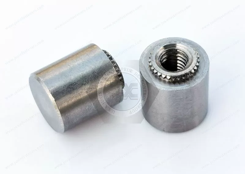
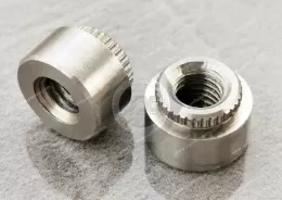
JUXIN FASTENERS supplies stainless steel broaching blind standoffs for printed circuit board mounting, electronic component spacing, and compact PCB stacking assemblies.
These press-fit fasteners use external broaching features to engage compatible mounting substrates, creating a retained support point without requiring loose mounting hardware.
The blind-end configuration provides a closed termination that can help limit screw penetration into sensitive assembly areas.
The product family includes JX-KFE and JX-KFSE references, with listed thread options including M3 and Unified #4 and #6.
Stainless steel material options include SUS302, SUS303, SUS316, SUS410, SUS420, and SUS430, subject to engineering suitability and product specifications.
Custom dimensions and standoff lengths can be reviewed for OEM applications.
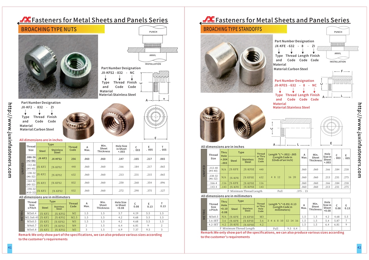
Refer to the relevant PDF specifications and CAD drawings on pages 41–42 for detailed dimensions and installation requirements.
Product Specification
Stainless Steel PCB Broaching Blind Standoffs – JX-KFE / JX-KFSE
Closed-End Press-Fit Spacing Solutions for Electronic Assemblies
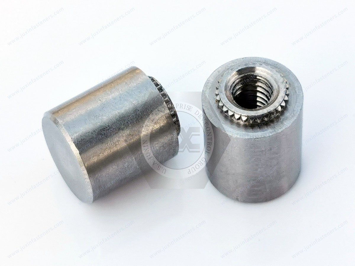
JUXIN FASTENERS provides stainless steel broaching blind standoffs for electronic assemblies requiring secure mounting points, controlled component spacing, and protection against excessive screw penetration.
These fasteners combine the mechanical spacing function of a standoff with a broaching-style press-fit attachment.
The external engagement features interact with a compatible mounting substrate, allowing the fastener to become a retained part of the assembly.
Unlike a conventional through-hole standoff, a blind standoff has a closed-end configuration. Where the selected design includes an internal blind thread, the screw cannot pass completely through the fastener body.
This feature is especially useful in compact electronic assemblies where circuit boards, electrical components, cables, or enclosure surfaces may be positioned behind the mounting point.
The JX-KFE and JX-KFSE product references should be confirmed against the applicable drawing to establish the exact blind-end geometry, threaded configuration, and available dimensions.
Product Characteristics
Product category: Broaching blind standoffs
Product references: JX-KFE and JX-KFSE
Primary material family: Stainless steel
Installation technology: Press-fit broaching engagement
Main applications: PCB mounting, electronic component spacing, and board stacking
Listed thread sizes: M3 and selected Unified #4 and #6 sizes
Available configurations: Subject to the specific product drawing
Standoff length: Standard drawing dimensions or custom requirements subject to review
Potential stainless steel grades include SUS302, SUS303, SUS316, SUS410, SUS420, and SUS430.
These grades have different machining characteristics, corrosion resistance, mechanical properties, and installation behavior. They should not be treated as equivalent substitutes.
The final material selection must consider the mounting substrate, required fastener geometry, operating environment, and expected mechanical loads.
For international specifications, the applicable stainless steel material designation and acceptance requirements should be confirmed on the approved engineering drawing.
How a Broaching Blind Standoff Works
A broaching blind standoff performs two functions within the same component.
Its external broaching features create mechanical engagement with the mounting substrate.
Its body establishes a controlled spacing distance between assembled components.
During installation, the fastener is aligned with a prepared mounting hole and pressed into place using suitable tooling.
The broaching features engage the surrounding substrate and provide resistance to movement and rotation.
The standoff then serves as a mounting or spacing point for another circuit board, bracket, or electronic component.
For a blind internally threaded configuration, the mating screw enters the threaded opening but cannot pass completely through the closed end.
This creates a physical limit to screw travel, although the permitted screw length must still be calculated to avoid bottoming out or overstressing the fastener.
The resulting connection depends on both the broaching retention and the strength of the mounting substrate.
Installation performance must therefore be evaluated as an assembly rather than as an isolated metal component.
Why Blind-End Geometry Matters in PCB Design
The main engineering advantage of a blind standoff is the ability to combine spacing with a closed-end mounting interface.
In compact electronic equipment, the area behind a mounting point may contain components that must not be contacted by a screw.
A conventional through-hole standoff may allow an excessively long screw to extend beyond the intended mounting region.
A blind standoff provides a physical barrier that can reduce this particular risk.
However, the blind end also limits the available thread depth.
Engineers must balance three requirements: sufficient screw engagement, adequate standoff length, and clearance from the closed end.
A longer screw is not necessarily better.
If the screw bottoms against the closed end before the intended joint is clamped, the assembly may appear tightened while failing to generate the required clamping force.
This is an important consideration for OEM equipment that may be assembled, serviced, or repaired using different screw lengths.
Screw Length and Thread Engagement
For blind threaded standoffs, the screw length should be selected using the complete assembled geometry.
The design review should consider the thickness of the attached component, any washers, the available internal thread depth, and the required thread engagement.
Manufacturing tolerances must also be included.
A practical design principle is to leave sufficient clearance between the screw tip and the blind end after the joint reaches its intended clamped condition.
The required engagement length depends on the mating screw, fastener material, thread size, loading, and application.
It should not be assigned using a single universal value for every stainless steel grade or PCB assembly.
Where the product has a blind unthreaded bore or another special interface, the corresponding drawing-defined requirements take precedence.
PCB Spacing and Board Stack-Up
Broaching blind standoffs can establish a defined distance between a printed circuit board and an adjacent structure.
This may include another PCB, a protective cover, an electronic module, or a chassis.
The required spacing should be determined from the complete assembly.
Relevant factors include the height of electronic components, board thickness, mounting surface geometry, standoff seating depth, and tolerance accumulation.
For example, an electronic control module may require a raised PCB to provide clearance for solder joints or components located on its underside.
The standoff length must be sufficient for the intended clearance without creating unnecessary overall assembly height.
When several standoffs support one PCB, their installed heights should be consistent enough to avoid unwanted board bending during fastening.
The installation process and mating component tolerances are therefore important parts of the design.
Stainless Steel Material Selection
JUXIN FASTENERS lists stainless steel material options including SUS302, SUS303, SUS316, SUS410, SUS420, and SUS430.
Different stainless steel grades may be appropriate for different manufacturing and service requirements.
Austenitic stainless steels such as 302 and 316 can offer corrosion resistance, but their manufacturing behavior and suitability for a specific broaching design require review.
Grade 303 is commonly selected for machinability, although its corrosion behavior differs from some other austenitic grades.
Martensitic grades such as 410 and 420 have different hardness and heat-treatment characteristics.
Ferritic grade 430 also differs in corrosion resistance and mechanical behavior.
A higher hardness is not automatically beneficial for a press-fit fastener.
The substrate must remain compatible with the broaching engagement features, and the selected fastener must withstand installation without unacceptable deformation or damage.
Material grade, condition, and any required surface treatment should be confirmed before production.
Thread Standards and Compatibility
Listed thread options include M3 and Unified #4 and #6 sizes.
Metric threads may be specified according to applicable ISO 261 and ISO 965 requirements.
Unified inch-series threads may be specified according to ASME B1.1.
Metric and Unified thread forms are not directly interchangeable.
The precise pitch, thread class, and mating screw requirements must be identified in the technical drawing.
Where an OEM project requires a different thread size, feasibility should be reviewed against the available body geometry and required wall thickness.
Substrate Compatibility and Installation
Broaching fasteners are designed to engage compatible substrates through their external broaching geometry.
They may be considered for selected PCB laminates and other suitable engineering materials, but performance varies according to substrate properties.
The actual PCB material, thickness, hole diameter, and local reinforcement structure must be evaluated.
Installation should use a controlled pressing operation with appropriate alignment and support.
Excessive insertion force may damage the substrate.
Insufficient engagement may reduce retention.
A hole that is too large can compromise the mechanical fit, while an undersized hole can increase local stress.
PCB copper features, plated holes, traces, and nearby components should also be considered when establishing mounting-hole locations.
Installation trials using representative production materials are recommended where the connection is mechanically significant.
Retention and Mechanical Reliability
A broaching standoff must remain secure during assembly and throughout its intended service life.
Depending on the application, relevant performance characteristics may include rotational resistance, axial retention, pushout resistance, and resistance to service-induced loading.
The required performance is influenced by the fastener geometry, mounting substrate, installation quality, and mating hardware.
No fixed torque-out or pushout value should be assumed for all PCB materials.
A fastener that performs adequately in one laminate may behave differently in another.
For critical applications, mechanical testing should reflect the actual production substrate and installation conditions.
Electrical Design Considerations
Stainless steel broaching standoffs are metallic components.
They must not be assumed to provide electrical insulation between mounted parts.
Where electrical isolation is required, the assembly may need suitable insulating washers, sleeves, coatings, or alternative mounting arrangements.
These features must be evaluated as part of the electrical and mechanical design.
For grounded mounting arrangements, electrical continuity should be verified according to the application requirements.
Industrial Applications
Industrial Control Electronics
PCB mounting points are required in programmable controllers, automation modules, and electronic control enclosures.
Blind standoffs may be considered when the mounting arrangement must maintain clearance while limiting screw intrusion into nearby components.
Telecommunications Equipment
Communication modules often contain compact PCB assemblies and multiple mounting levels.
Broaching blind standoffs can support board spacing where the substrate and mounting geometry are suitable.
Medical and Laboratory Equipment
Electronic instruments may require controlled board positioning within compact housings.
A blind-end mounting interface can be useful where excessive screw penetration must be avoided.
Suitability for regulated equipment depends on the complete design and applicable qualification requirements.
Industrial Measurement Systems
Sensors, measurement modules, and electronic monitoring assemblies may use standoffs to maintain separation between circuit boards and structural components.
Embedded Computing and Networking Hardware
Compact electronic enclosures often combine dense PCB layouts with limited internal clearance.
Blind standoffs may help designers manage mechanical attachment and screw penetration within the available space.
OEM Electronic Enclosures
Custom enclosure assemblies may require mounting hardware that supports repeatable production and simplifies handling during assembly.
A retained broaching standoff can reduce dependence on loose spacers where the installation method is compatible.
Blind vs. Through-Hole Broaching Standoffs
Blind and through-hole standoffs may perform similar spacing functions, but their internal geometries lead to different design considerations.
A blind threaded standoff limits screw travel and can help protect components behind the mounting point.
A through-hole standoff allows a screw or other mating component to pass through the body, depending on the selected configuration.
Blind standoffs require particular attention to available thread depth and screw bottoming.
Through-hole standoffs require consideration of screw protrusion and clearance beyond the mounting point.
The correct choice depends on the required mounting method, assembly accessibility, service requirements, and surrounding components.
Alternative PCB Mounting Solutions
Conventional loose standoffs may be appropriate for prototypes or low-volume assemblies.
Self-clinching standoffs are generally associated with compatible ductile metal panels rather than direct installation into PCB laminate.
Broaching nuts provide retained threaded attachment points but may not provide the same spacing function as a dedicated standoff.
Surface-mount standoffs can be considered for designs that incorporate suitable solder-based mounting processes.
Plastic spacers may be appropriate where electrical insulation or low component weight is a priority.
Selection should consider installation equipment, material compatibility, mechanical loading, electrical requirements, and total assembly cost.
OEM Design and Procurement Considerations
Engineering teams should establish the required spacing, thread geometry, blind-hole depth, mounting substrate, and mechanical performance.
Purchasing and supplier development teams should confirm the exact part number, approved drawing, material specification, inspection requirements, and commercial quantities.
For an OEM project, a complete RFQ should include the following information:
Product reference: JX-KFE or JX-KFSE
Required blind-end configuration and thread details
Standoff length and external dimensions
PCB material and thickness
Mounting-hole dimensions and tolerances
Stainless steel grade and material condition
Mating screw details and required engagement
Application loads and installation requirements
Estimated order quantity and annual demand
Required drawings, samples, inspection, and packaging
Custom dimensions may be reviewed according to manufacturing feasibility.
A sample approval process is particularly useful when the mounting substrate or installation geometry differs from an existing validated application.
Frequently Asked Questions
What is a broaching blind standoff?
A broaching blind standoff is a retained press-fit spacing component with a closed-end configuration.
It can provide a mounting interface while helping limit screw penetration beyond the intended attachment point.
What is the difference between a blind standoff and a through-hole standoff?
A blind standoff has a closed end, while a through-hole design permits passage through the body.
The correct selection depends on the mating screw, required thread engagement, and surrounding assembly clearance.
Can stainless steel broaching standoffs be installed directly into PCBs?
They may be suitable for compatible PCB materials, but mounting-hole geometry, substrate thickness, and installation performance must be verified.
Are M3 and #4 threads interchangeable?
No. Metric M3 and Unified #4 threads have different dimensional and thread specifications.
Can a blind standoff prevent damage from an excessively long screw?
A closed end can limit screw penetration beyond the fastener body.
However, an excessively long screw may bottom out and prevent proper clamping, so screw length must still be controlled.
Can custom lengths be supplied?
Custom standoff dimensions can be submitted to JUXIN FASTENERS for engineering and manufacturing feasibility review.
Related Fastening Solutions
Through-Hole PCB Broaching Standoffs – JX-KFE / JX-KFSE
For board spacing applications requiring a through-hole mounting interface.
PCB Broaching Nuts – JX-KF2 / JX-KFS2
For retained internally threaded attachment points in compatible PCB materials.
Non-Threaded PCB Broaching Fasteners
For applications requiring a retained unthreaded mounting interface.
Self-Clinching Standoffs
For permanent spacing and mounting in compatible metal panels.
Self-Clinching Nuts
For creating reusable internal threads in suitable sheet metal assemblies.
These related product categories can be linked to the corresponding JUXIN FASTENERS product pages to support engineering comparison and product selection.
Request a Technical Review and OEM Quotation
JUXIN FASTENERS supports industrial fastening requirements for electronic equipment manufacturers, OEM design teams, procurement departments, and supply chain organizations.
For stainless steel broaching blind standoff inquiries, please provide the applicable drawing, required dimensions, material grade, PCB specifications, mating hardware details, and expected purchasing quantities.
Our team can review the technical requirements and prepare a quotation based on the confirmed product specification.
Email: info@juxinfasteners.com
Website: www.juxinfasteners.com
JUXIN FASTENERS – Industrial Fastening Solutions for Electronic Assembly and OEM Manufacturing.
Product Packaging
Stainless steel JX-KFE and JX-KFSE broaching blind standoffs can be packed using protective inner packaging and export cartons, with palletized shipment arrangements where required.
Packaging quantities, carton dimensions, labels, and pallet configurations are determined according to product size, order volume, and customer specifications.
Customized OEM packaging and identification requirements can be reviewed before order confirmation.
For bulk orders and packaging inquiries, contact info@juxinfasteners.com.
Website: www.juxinfasteners.com
Product Pictures
Contact Us
Tel.:
+86 020 8621 0320
+86 020 3121 6067
E-mail:
Technical Support:
Navigation
SEND INQUIREY