Call Us
+86 136 6007 9809
Call Us
+86 136 6007 9809

JX-N10 Broaching Standoffs – PCB Stacking and Spacing Solutions
JX-N10 broaching standoffs are designed to provide fixed spacing and mechanical mounting points in printed circuit board assemblies.
Material: Stainless steel.
Broaching standoffs are installed into appropriately prepared PCB holes, allowing the mounting feature to engage the board material without requiring a conventional threaded hole in the substrate.
Threaded and unthreaded broaching standoff configurations can be used for board-to-board stacking, PCB-to-panel spacing, electronic module support, and component positioning, subject to the approved product design.
Typical applications include industrial electronics, telecommunications equipment, control systems, instrumentation, embedded computing, and electronic enclosure assemblies.
Standoff dimensions, mounting-hole requirements, thread configurations, and spacing heights must be selected according to the PCB design and applicable technical drawing.
Custom sizes and OEM configurations can be reviewed based on customer drawings and assembly requirements.
Product Specification
JX-N10 Broaching Standoffs – Engineering and OEM PCB Mounting Solutions
JX-N10 broaching standoffs are stainless steel fastening components intended for electronic assemblies requiring controlled spacing, mechanical support, and repeatable PCB positioning.
Broaching technology provides a method of securing compatible fasteners into prepared holes in printed circuit board materials.
The JX-N10 series is positioned for engineers and OEM procurement teams seeking PCB stacking hardware, press-fit standoff solutions, and compact electronic mounting components.
The exact JX-N10 configuration must be confirmed against the approved product drawing before final selection.
Product Function and Construction
A broaching standoff creates a defined separation between two circuit boards or between a PCB and another structural component.
Its body establishes the required spacing height, while its mounting feature provides retention within the prepared substrate.
Depending on the selected design, the opposite end may provide a threaded connection or an unthreaded locating feature.
The mounting arrangement should be selected according to the required assembly load, service access, and board construction.
Unlike a conventional loose spacer, a properly installed broaching standoff can remain associated with its mounting board during subsequent assembly operations.
This can simplify component handling and improve repeatability during PCB production.
Threaded and Unthreaded Configurations
Threaded broaching standoffs provide a fastening point for a compatible machine screw.
They are useful where an upper PCB, bracket, shield, or other component must be mechanically secured at a defined distance.
The screw thread must match the approved standoff thread specification.
Unthreaded broaching standoffs may provide spacing, locating, or support functions without a threaded fastening interface.
Their retention and assembly requirements depend on the particular geometry.
Threaded and unthreaded products should not be treated as interchangeable simply because their outer diameters or overall lengths appear similar.
For the JX-N10 series, the availability of each configuration must be verified against the applicable drawing.
Stainless Steel Material
The supplied material specification identifies stainless steel.
Stainless steel may be selected for its corrosion resistance, dimensional stability, and suitability for many electronic equipment environments.
Actual stainless steel grade, hardness, and surface condition must be confirmed in the purchasing specification.
Different stainless steel grades can behave differently during broaching installation.
Material hardness and deformation characteristics may influence insertion force and retention performance.
Where appropriate, material requirements can be defined using recognized ASTM, EN, or ISO specifications.
No particular grade, mechanical strength, or corrosion performance is assumed without verified technical data.
PCB Broaching Installation
Broaching fasteners rely on a controlled mechanical engagement between the fastener mounting feature and the prepared PCB hole.
The installation process requires a suitable press, correct alignment, and appropriate support beneath the circuit board.
During installation, the fastener feature engages the hole wall to develop mechanical retention.
The board material, finished hole diameter, board thickness, and fastener geometry must be compatible.
Excessive installation force can damage the PCB laminate or surrounding circuitry.
Insufficient installation engagement can reduce retention and allow movement during subsequent assembly.
Installation conditions should be established using the approved product drawing and validated on the intended PCB construction.
PCB Hole Preparation and Tolerance Control
The finished PCB hole is a critical feature in broaching standoff performance.
Engineers should specify the finished hole diameter rather than relying only on the nominal drill size.
Plating thickness, fabrication tolerances, laminate characteristics, and local board construction can affect the final hole geometry.
Hole location must also account for the positions of nearby copper features, vias, traces, and components.
A mounting hole that is too small may increase insertion stress and risk laminate damage.
A hole that is too large may reduce mechanical retention.
The acceptable hole range must be established from the specific JX-N10 drawing.
No universal mounting-hole tolerance should be assumed for every broaching standoff size.
Board Thickness and Substrate Compatibility
The suitability of a broaching standoff depends on the board thickness and substrate construction.
Common PCB materials can vary significantly in stiffness, strength, and resistance to local deformation.
Standard FR-4 boards, multilayer PCBs, and specialized electronic substrates may require different installation validation.
Thin boards can be more sensitive to bending during insertion.
Thicker boards may require different mounting feature dimensions.
The selected fastener must be compatible with the finished board thickness and hole geometry.
The engineering review should also consider local copper distribution, board edge distance, and nearby component clearance.
Board-to-Board Stacking Applications
PCB stacking is a common application for standoffs.
Multiple boards may need to be positioned at a defined distance to accommodate connectors, electronic components, shielding, or airflow.
The selected standoff height must account for the complete mechanical stack.
This includes PCB thickness, connector engagement, component height, fastening hardware, and any required service clearance.
The nominal standoff length alone does not determine the final clearance between electrical components.
For connectorized board stacks, tolerance accumulation can create unwanted loading on the connectors.
Engineers should verify that the standoff height and connector mating geometry are compatible across the full tolerance range.
PCB-to-Chassis and PCB-to-Panel Spacing
Broaching standoffs may also be used where a circuit board must be positioned relative to a metal panel, housing, or supporting component.
The mounting system should maintain adequate separation between conductive surfaces and sensitive circuitry.
Required electrical clearances must be determined from the equipment design and applicable safety requirements.
A standoff is a mechanical support component and should not automatically be considered an electrical insulator.
Stainless steel is electrically conductive.
Where electrical isolation is necessary, an appropriate insulating component or alternative mounting arrangement must be included.
Electronic Assembly Applications
Industrial Control Electronics
Broaching standoffs can support compact PCB mounting arrangements in control modules and automation equipment.
They may reduce loose hardware handling during production when compatible with the assembly process.
Telecommunications Equipment
Board stacking arrangements in telecommunications hardware often require controlled spacing and alignment.
Standoff placement should account for connectors, shielding structures, and service access.
Embedded Computing
Embedded computing systems may use multiple PCBs within compact enclosures.
Standoffs help maintain mechanical separation while allowing designers to accommodate connectors and components.
Instrumentation and Measurement Devices
Instrumentation assemblies may require stable board positioning and repeatable component clearances.
Mechanical stability should be evaluated against the expected operating environment.
Electronic Modules and Sensor Assemblies
Compact sensor modules can benefit from dedicated mounting points and defined board separation.
Designers should consider installation stress, vibration exposure, and the accessibility of the assembled hardware.
Engineering Comparison: Broaching Versus Self-Clinching Standoffs
Broaching standoffs are generally associated with suitable PCB or other compatible substrate mounting applications.
Self-clinching standoffs are commonly used in ductile sheet metal where controlled material flow around the mounting feature creates retention.
These installation methods are not equivalent.
A self-clinching metal-panel standoff should not be assumed suitable for installation into a PCB.
Similarly, a PCB broaching standoff should not automatically be specified for a metal panel.
The correct mounting technology depends on the substrate material, thickness, hole geometry, and required retention performance.
Engineering Comparison: Broaching Versus SMT Standoffs
Surface-mount standoffs are designed for solder attachment through an appropriate PCB assembly process.
Broaching standoffs use a mechanical installation method.
SMT mounting may be attractive when the fastener can be incorporated into the established soldering process.
Broaching may be preferable where a mechanical press-fit mounting operation is appropriate and compatible with the board.
The selection should consider manufacturing sequence, board accessibility, mechanical loads, inspection requirements, and total assembly cost.
Neither method is universally superior.
Engineering Comparison: Broaching Versus Loose Spacers
Conventional loose spacers can provide board separation without requiring a broaching mounting operation.
However, loose spacers must be positioned and handled during final assembly.
Broaching standoffs may reduce the number of independently handled components after installation.
Their value depends on assembly volume, service requirements, installation cost, and the complexity of the PCB design.
For OEM production, the total cost should include fastener installation, board preparation, inspection, and final assembly labor.
Mechanical Retention and Assembly Reliability
A broaching standoff must remain sufficiently retained during subsequent handling and assembly operations.
Relevant performance considerations may include push-out resistance, rotational stability, and resistance to movement under operating loads.
The applicable tests depend on the fastener design and intended function.
The board itself may be the limiting component.
Excessive mechanical loads can damage the laminate even when the metal fastener remains intact.
Engineers should evaluate the complete joint rather than relying only on the strength of the stainless steel component.
Common Failure Modes and Prevention
Laminate cracking may occur when installation stress exceeds the local board capacity.
Insufficient retention may result from an oversized hole or unsuitable substrate.
Board warpage may occur if the PCB is not adequately supported during installation.
Misalignment can create uneven loading and damage the hole.
Incorrect standoff height can produce connector stress or insufficient component clearance.
Excessive tightening torque in threaded versions can overload the fastener or supporting PCB.
These risks should be addressed through correct hole design, controlled installation, dimensional verification, and application-specific testing.
Dimensional and Technical Specifications
Product series: JX-N10.
Product type: Broaching standoff for PCB mounting and spacing.
Material: Stainless steel.
Mounting method: Mechanical broaching into a compatible prepared substrate.
Functional options: Threaded or unthreaded configurations, subject to drawing confirmation.
Typical functions: PCB stacking, spacing, positioning, and component support.
Mounting substrate: Compatible printed circuit board material, subject to validation.
Thread dimensions: According to the approved JX-N10 drawing.
Standoff height: According to the selected specification or approved OEM drawing.
Mounting-hole diameter: According to the applicable fastener specification.
Installation force: To be established through the approved installation requirements.
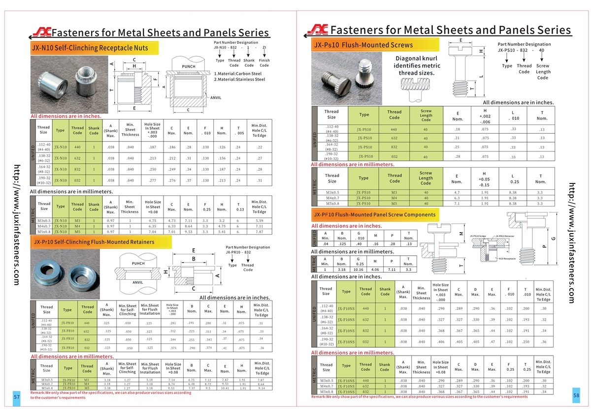
Detailed dimensional information: Refer to the applicable product PDF and CAD documentation, pages 57–58, after verifying that the drawing corresponds to JX-N10.
Custom dimensions: Subject to engineering review and manufacturing feasibility.
Thread Standards and Dimensional Verification
Where threaded versions are specified, the thread system must be clearly identified.
Unified inch threads may be defined using ASME B1.1.
ISO metric threads may be defined using applicable ISO thread standards.
A nominal metric diameter is not directly interchangeable with a similarly sized Unified thread.
Engineers should verify diameter, pitch, thread engagement, and mating hardware.
Threaded standoffs should be evaluated for appropriate engagement length and tightening torque.
Exact available JX-N10 thread sizes must be confirmed from the approved product specification.
OEM Design and Qualification Checklist
The engineering review should establish the PCB material and finished thickness.
The mounting-hole diameter and fabrication tolerances must be defined.
The required board-to-board or board-to-panel spacing should be specified.
The design should identify the required threaded or unthreaded configuration.
Nearby copper features, vias, components, and connectors should be checked for clearance.
The installation method and support tooling must be suitable for the actual PCB.
Prototype samples should be tested for installation damage and retention performance.
For critical applications, environmental and mechanical qualification requirements should be defined before production approval.
Frequently Asked Questions
What is a broaching standoff?
A broaching standoff is a mounting and spacing fastener that uses a mechanical engagement feature to secure itself into a compatible prepared substrate.
Can broaching standoffs be used for PCB stacking?
Yes. They can provide fixed spacing between boards when the mounting geometry and mechanical requirements are appropriate.
Are threaded and unthreaded broaching standoffs interchangeable?
No. They provide different fastening and locating functions and must be selected according to the intended assembly.
Can JX-N10 standoffs be installed in every PCB material?
No. Installation suitability depends on substrate construction, board thickness, hole dimensions, and the fastener design.
Does a stainless steel standoff provide electrical insulation?
No. Stainless steel is electrically conductive.
Can custom standoff heights be supplied?
Custom dimensions may be evaluated according to customer drawings and manufacturing feasibility.
How should a broaching standoff be specified for procurement?
The RFQ should include the exact model, approved drawing, material, mounting-hole requirements, standoff height, thread configuration, quantity, and application details.
Related Products and Internal Linking
For other PCB mounting configurations, explore Broaching Standoffs – JX-KFE / JX-KFSE.
For threaded metal-panel mounting points, review Self-Clinching Threaded Standoffs.
For quick-release board support, see JX-SKC Self-Clinching Detachable Standoffs.
For screwless PCB retention, explore JX-SSC / JX-SSS Spring-Action Standoffs.
For alternative PCB assembly processes, review Surface-Mount PCB Fasteners.
These product names should link to their corresponding verified pages on www.juxinfasteners.com.
OEM Procurement and Supply Chain Considerations
OEM purchasing teams should request a complete part specification rather than sourcing only by the generic term PCB standoff.
Two standoffs with similar outside dimensions may have different mounting geometries and installation requirements.
The supplier qualification process should verify drawing revision, material specification, dimensional consistency, and compatibility with the customer's PCB fabrication process.
For repeat orders, the approved mounting-hole specification and assembly method should remain controlled.
Where required, inspection records, material documentation, sample approval, and lot traceability should be agreed during sourcing.
Request an OEM Quotation
Juxin Fasteners supports OEM inquiries for stainless steel PCB broaching standoffs and related electronic fastening components.
Please provide your JX-N10 drawing or required dimensions, PCB material and thickness, mounting-hole details, threaded or unthreaded configuration, spacing height, expected order quantity, and annual demand.
Our team can review the requirements for product selection, customization, and quotation.
Email: info@juxinfasteners.com
Website: www.juxinfasteners.com
Juxin Fasteners – Industrial Fastening Solutions for Electronics, Engineering, and OEM Supply Chains.
Product Packaging
Packaging and Export Protection
Juxin Fasteners provides protective export packaging for JX-N10 stainless steel broaching standoffs.
Packaging is selected to protect the broaching features, internal threads where applicable, and critical mounting dimensions during storage and international transportation.
Standard packaging may include protective inner bags or small boxes, export cartons, and palletized shipments when required.
Packaging labels can identify the part number, material, dimensions, quantity, and production batch according to agreed customer requirements.
OEM packaging options include customer-specific labels, barcodes, defined packing quantities, protective separators, custom carton configurations, and pallet arrangements.
Final packaging quantities and shipment specifications are confirmed according to the product dimensions, order volume, and customer purchasing requirements.
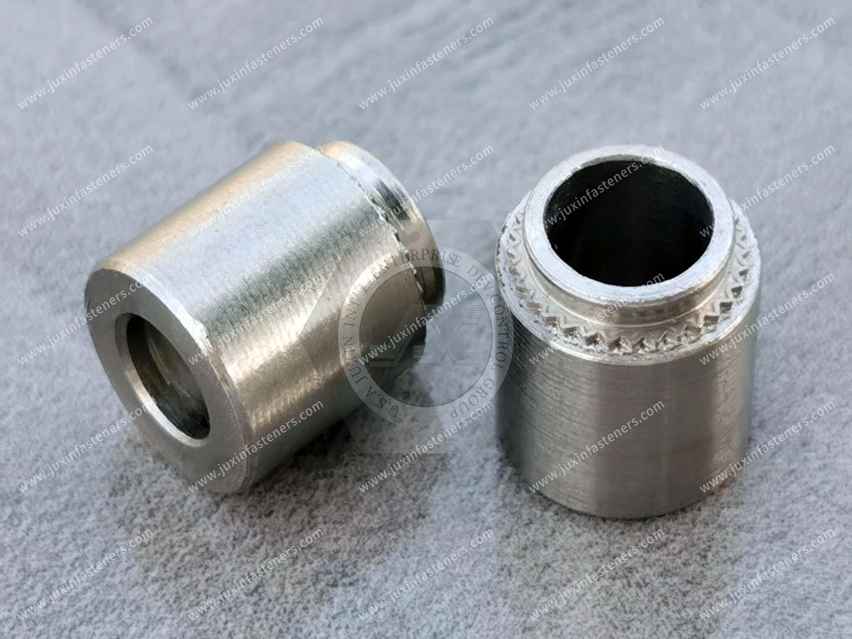
Product Pictures
Contact Us
Tel.:
+86 020 8621 0320
+86 020 3121 6067
E-mail:
Technical Support:
Navigation
SEND INQUIREY