Call Us
+86 136 6007 9809
Call Us
+86 136 6007 9809

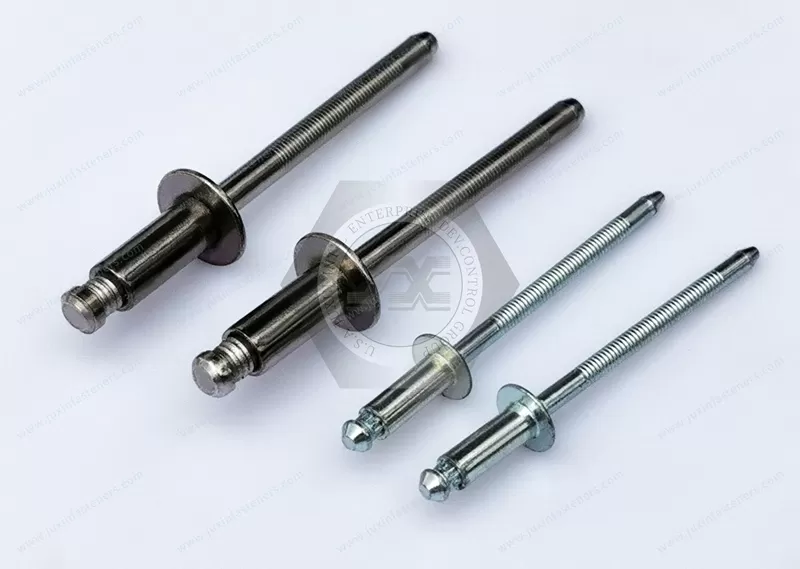
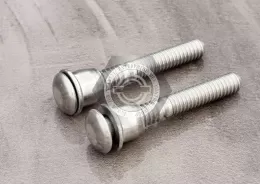
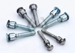
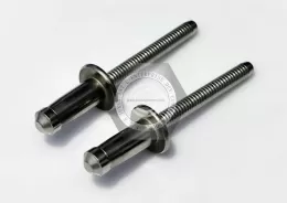
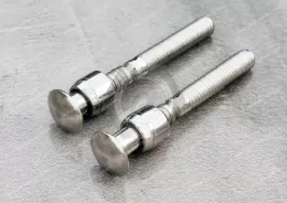
JUXIN FASTENERS supplies domed head high-strength blind rivets with a visible external mandrel-locking feature for secure one-sided fastening.
Available in steel body/steel mandrel and stainless steel body/stainless steel mandrel configurations.
Designed for demanding structural assemblies, these rivets support mandrel retention and joint reliability in commercial vehicles, trailers, industrial machinery, and fabricated sheet metal equipment.
Product Specification
Domed Head High-Strength Blind Rivets with External Lock
Externally Locked Structural Blind Rivets for OEM and Industrial Manufacturing
JUXIN FASTENERS supplies domed head high-strength blind rivets with an externally visible mandrel-locking feature for industrial applications requiring one-sided installation,
dependable stem retention, and structural fastening performance.
These products are relevant to engineering and procurement searches for externally locked structural blind rivets, dome head structural breakstem rivets,
positive mandrel retention rivets, mechanically locked blind rivets, and high-strength self-plugging blind rivets.
The distinguishing feature of this product series is its external mandrel-locking arrangement.
After correct installation, the retained mandrel is mechanically secured, and the locking feature can be identified at the accessible rivet head.
The domed head provides a raised bearing surface on the installation side, while the rivet body expands on the blind side to secure the assembled components.
JUXIN offers two material combinations:
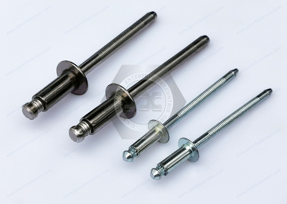
Steel body + steel mandrel
Stainless steel body + stainless steel mandrel
Both configurations are specified with a domed head.
The exact body diameter, grip range, head geometry, material grade, mechanical ratings, locking construction, and installation tooling must be confirmed using the applicable product drawing.
1. What Are Domed Head High-Strength Blind Rivets with External Lock?
An externally locked structural blind rivet is a fastening component designed for installation from one accessible side of an assembly.
It generally consists of a rivet body and a mandrel.
During installation, a compatible riveting tool pulls the mandrel through the body. This action causes the blind-side portion of the rivet body to deform and form a retaining structure behind the joined materials.
As the installation process is completed, the mandrel separates at its designed break location.
The external locking feature secures the retained portion of the mandrel at or near the accessible rivet head.
This retained mandrel may contribute to the fastener's installed shear performance and overall structural behavior.
The mechanical locking arrangement is particularly relevant where loose mandrels are unacceptable or where vibration resistance is an important design consideration.
Actual joint performance depends on the specific fastener construction, substrate materials, and installation quality.
2. External Mandrel Locking: The Key Engineering Feature
2.1 What Is an External Lock?
An external lock is a mechanical feature that secures the retained mandrel and remains visible or externally identifiable after installation.
In certain externally locked structural blind rivet systems, compatible installation tooling forms or activates the locking feature near the rivet head.
The exact locking method varies by product design.
The visible feature should be evaluated against the applicable product drawing and installation criteria.
2.2 External Lock Versus Internal Lock
Externally locked structural blind rivets and internally locked structural blind rivets both use mechanical retention principles, but their locking arrangements differ.
An external lock can be inspected at the accessible head.
An internal lock is concealed within the rivet construction.
This difference can influence:
Installation tooling
Inspection methods
Mandrel break characteristics
Production quality controls
Fastener interchangeability
The two types should not be treated as interchangeable without engineering verification.
2.3 Positive Mandrel Retention
The external locking feature is designed to retain the mandrel after setting.
Positive retention helps address the risk of the retained stem loosening under service conditions.
For structural assemblies, the retained mandrel may also contribute to the fastener's mechanical performance.
However, the presence of an external lock does not establish a universal retention-force value or guarantee performance under every operating condition.
Product-specific testing and approved installation procedures remain necessary.
2.4 Visible Lock Inspection
An externally identifiable locking feature can support production inspection.
Operators may be able to check whether the expected locking condition is present at the installed head.
Inspection should be based on defined acceptance criteria, including any specified mandrel position, locking geometry, or setting characteristics.
A visually recognizable feature alone is not sufficient to prove that every mechanical requirement has been satisfied.
3. Domed Head Design and Installation Benefits
The domed head, also called a dome head or button-style head in some industrial catalogs, remains raised above the material surface after installation.
Unlike a countersunk head, a conventional domed head does not require a matching countersunk recess.
This can simplify hole preparation in suitable sheet metal assemblies.
Potential benefits include:
One-sided fastening
A defined bearing surface on the accessible side
No countersinking for conventional domed-head installation
A consistent finished head appearance
Compatibility with many fabricated metal assemblies
Easier access for visual inspection of the head and external locking feature
The exact head diameter and head height must be verified for the selected rivet.
Where flushness or surface clearance is critical, a domed head may not be appropriate.
4. Available Materials and Selection Considerations
4.1 Steel Body + Steel Mandrel
Steel body and steel mandrel high-strength blind rivets may be considered for fabricated steel assemblies where structural fastening performance and one-sided access are important.
Potential applications include:
Commercial vehicle body structures
Truck and trailer components
Fabricated steel brackets
Industrial machinery housings
Equipment frames
Heavy-duty sheet metal panels
Engineering selection should consider:
Steel grade
Rivet diameter
Grip range
Shear and tensile requirements
Surface finish
Corrosion environment
Installation hole dimensions
Compatible tooling
Any protective coating must be specified and confirmed for the actual product.
4.2 Stainless Steel Body + Stainless Steel Mandrel
Stainless steel body and stainless steel mandrel configurations may be considered for industrial assemblies requiring corrosion resistance and stainless steel material compatibility.
Potential applications include:
Outdoor industrial equipment
Stainless steel equipment housings
Selected transportation components
Industrial processing equipment
Fabricated enclosures
Machinery exposed to moisture
Selection should consider the exact stainless steel grade, joint loading, environmental exposure, and installation equipment.
The general term stainless steel does not identify a specific alloy.
Grades such as 304 or 316 should be listed only when confirmed for the selected product.
5. Shear Strength, Tensile Strength, and Structural Performance
5.1 Shear Strength
Shear loading acts across the fastener, generally parallel to the plane of the joined components.
A structural blind rivet's shear performance depends on its diameter, body material, mandrel construction, and installed condition.
In certain structural designs, the retained mandrel contributes to the installed shear resistance.
Exact shear values must be obtained from verified product data.
5.2 Tensile Strength
Tensile loading tends to separate the joined materials.
The tensile resistance of a riveted joint depends on both the fastener and the surrounding components.
Potential failure modes include fastener failure, head pull-through, blind-side pull-through, or deformation of the substrate.
A high tensile rating for an individual rivet does not automatically establish the allowable tensile load of the complete assembly.
5.3 Mandrel Retention and Vibration
The positive locking feature is intended to keep the retained mandrel secured after installation.
This is particularly relevant in assemblies exposed to vibration or repeated operating loads.
However, vibration resistance depends on the complete joint design and must be evaluated for the intended service conditions.
5.4 Hole Fill and Rivet Expansion
During setting, the mandrel causes the rivet body to expand and form the blind-side retaining structure.
Certain structural blind rivet designs provide enhanced radial expansion and hole-fill behavior.
This does not mean that every oversized or irregular installation hole is acceptable.
Hole dimensions and tolerances must comply with the applicable product specification.
5.5 Clamp-Up and Joint Integrity
Proper installation brings the workpieces together and forms the required blind-side head.
The resulting clamp-up behavior depends on the rivet construction, grip thickness, substrate materials, and setting process.
Where a defined clamp force is required, engineering verification and appropriate testing are necessary.
6. Engineering Selection Guide
6.1 Determine the Required Rivet Diameter
Rivet diameter influences the available mechanical performance, installation hole size, and tooling requirements.
Selection should consider:
Applied shear loading
Applied tensile loading
Substrate strength
Joint geometry
Available edge distance
Fastener spacing
Installation access
The selected diameter must be supported by the applicable engineering design.
6.2 Confirm the Grip Range
Grip range is the allowable combined thickness of the joined materials.
The selected rivet must accommodate the actual minimum and maximum assembled thickness.
Manufacturing tolerances, coatings, and intermediate layers may influence the finished grip thickness.
Do not assume that every externally locked structural rivet has a wide grip range.
Use the approved range for the specific part number.
6.3 Verify the Installation Hole
Hole diameter and quality are critical to reliable setting.
An undersized hole may prevent correct insertion or damage the fastener.
An oversized hole may affect body support, blind-side formation, and joint performance.
Use the specified hole diameter and tolerance.
6.4 Check Edge Distance and Rivet Spacing
Fastener arrangement influences load transfer and the risk of substrate tearing or deformation.
Edge distance and spacing should be established according to the joint materials, loading, and relevant engineering requirements.
6.5 Evaluate Material Compatibility
Rivet body material, mandrel material, and substrate material should be selected with consideration for corrosion exposure and mechanical compatibility.
Where dissimilar metals are used, galvanic corrosion may require additional design measures.
6.6 Confirm Installation Tooling
Externally locked structural blind rivets may require a dedicated nosepiece or installation tool arrangement to form the locking feature correctly.
A standard blind rivet tool should not be assumed suitable solely because its nominal capacity matches the rivet diameter.
Tool compatibility must be verified before production use.
7. Installation Procedure for Externally Locked Structural Blind Rivets
A controlled installation process is important for reliable mandrel locking and joint consistency.
Step 1: Review the Product Specification
Confirm the rivet diameter, grip range, material combination, head dimensions, and locking requirements.
Step 2: Prepare the Installation Holes
Produce aligned holes within the specified diameter and tolerance.
Remove burrs and inspect for excessive deformation.
Step 3: Verify the Material Thickness
Confirm that the assembled thickness falls within the approved grip range.
Step 4: Select the Correct Installation Tool
Use the specified riveting tool and compatible nosepiece.
Where the locking mechanism requires a dedicated nose assembly, that assembly must be used.
Step 5: Insert the Rivet
Position the rivet through the prepared hole and seat the domed head against the accessible surface.
Step 6: Complete the Setting Operation
Operate the tool according to the approved installation procedure.
The mandrel is pulled, the blind-side retaining structure forms, and the designed locking process is completed.
Step 7: Inspect the External Lock
Check the installed head, locking feature, and retained mandrel condition against the approved acceptance criteria.
Step 8: Verify Joint Quality
Where required, inspect representative blind-side formations and perform appropriate mechanical or destructive testing.
Step 9: Maintain Production Records
Record inspection results and tool maintenance information according to the OEM quality plan.
8. Common Installation Problems and Prevention
8.1 External Lock Not Properly Formed
An incorrectly formed locking feature may indicate unsuitable tooling, incomplete setting, or another installation issue.
Prevention: Use the approved tool and nosepiece and establish specific lock-inspection criteria.
8.2 Abnormal Mandrel Break Position
A mandrel that breaks outside the acceptable position may indicate an installation problem.
Prevention: Verify the rivet specification, grip range, and tool condition.
8.3 Incorrect Grip Range
A rivet installed outside its approved grip range may not form the intended blind-side geometry.
Prevention: Check the complete assembled thickness, including tolerances.
8.4 Oversized Installation Hole
An oversized hole may reduce body support and affect setting consistency.
Prevention: Control hole diameter and inspect the preparation process.
8.5 Incompatible Tooling
An unsuitable nosepiece may prevent correct locking or damage the rivet.
Prevention: Verify tooling compatibility for the exact product.
8.6 Incomplete Blind-Side Formation
Improper installation may result in inadequate blind-side deformation.
Prevention: Use approved setting procedures and inspect representative samples.
8.7 Corrosion or Material Mismatch
Unsuitable material combinations may contribute to joint deterioration.
Prevention: Select verified materials and finishes appropriate to the service environment.
9. Industrial Applications and Engineering Solutions
9.1 Commercial Vehicles and Truck Bodies
Externally locked structural blind rivets may be considered for truck body components, equipment panels, fabricated brackets, and selected commercial vehicle assemblies.
Mandrel retention and one-sided installation can be useful in assemblies exposed to vibration and restricted access.
Joint strength and fatigue requirements must be evaluated.
9.2 Trailer and Transportation Equipment
Potential applications include trailer structures, fabricated body components, equipment housings, and sheet metal assemblies.
Engineers should consider dynamic loading, corrosion exposure, and installation consistency.
9.3 Industrial Machinery
Potential applications include machinery housings, fabricated supports, equipment covers, and structural sheet metal components.
External lock inspection may be useful where production quality controls require confirmation of mandrel retention.
9.4 Electrical Equipment and Power Distribution Cabinets
These rivets may be evaluated for selected fabricated cabinet frames, equipment housings, and structural enclosure components.
Fastener selection must account for mechanical loading, electrical clearance, grounding requirements, and corrosion.
9.5 AI Data Center Equipment and Metal Cabinets
Potential applications include selected equipment cabinets, fabricated sheet metal frames, and supporting enclosure structures.
The joint design should consider service access, vibration, assembly repeatability, and material compatibility.
9.6 HVAC and Industrial Ventilation Equipment
Externally locked structural blind rivets may be considered for selected equipment housings, fabricated brackets, and structural sheet metal assemblies.
Vibration, corrosion exposure, and installation access should be reviewed.
9.7 Outdoor Industrial Equipment
Stainless steel configurations may be considered for selected outdoor equipment and industrial housings.
The required corrosion resistance must be established using the actual material grade and environmental conditions.
10. Production Management and Quality Assurance
For production managers, selecting externally locked structural blind rivets affects tooling, installation consistency, inspection, and production cost.
Important process considerations include:
Correct rivet identification
Controlled installation hole dimensions
Grip range verification
Dedicated tooling where required
Nosepiece maintenance
Operator training
External lock inspection
Mandrel break-position checks
Blind-side formation verification
Rework criteria
Batch traceability where required
The externally visible locking feature can support inspection, but it should be evaluated using defined acceptance criteria rather than appearance alone.
A repeatable production process is essential for consistent joint performance.
11. Purchasing and Supply Chain Considerations
OEM purchasing teams should evaluate structural blind rivets based on technical suitability and total production requirements.
Relevant factors include:
Engineering Compatibility
The supplied rivet must match the approved diameter, grip range, material, head style, and locking requirements.
Installation Equipment
Dedicated nosepieces or tooling may influence implementation cost and production planning.
Quality Documentation
Dimensional reports, material requirements, and inspection records should be agreed upon according to the project specification.
Production Capacity
Forecast quantities, batch requirements, packaging, and delivery schedules should be considered during supplier selection.
Change Control
Changes to rivet geometry, material, mandrel construction, or installation tooling should be reviewed before implementation.
12. OEM Customization and Drawing-Based Manufacturing
JUXIN FASTENERS welcomes OEM and industrial sourcing inquiries for high-strength blind rivets and related fastening components.
Customer requirements may include:
Rivet body diameter
Grip range
Domed head dimensions
Body and mandrel materials
Material grades
External locking geometry
Surface treatment
Dimensional tolerances
Installation hole requirements
Mechanical performance criteria
Installation tooling
Packaging and labeling
Production quantities
Quality inspection requirements
Custom dimensions and configurations are subject to engineering review and manufacturing feasibility.
The customer drawing and applicable specifications should be confirmed before production approval.
13. Metric and Inch Dimension References
Industrial structural blind rivets are used in markets with both metric and inch-based dimensional designations.
Common mathematical conversions include:
3/16 inch = 4.7625 mm
1/4 inch = 6.35 mm
3/8 inch = 9.525 mm
These conversions are provided for reference only.
A nominal metric rivet should not automatically be substituted for an inch-designated rivet without verifying the actual manufactured dimensions, installation hole, grip range, head geometry, and mechanical requirements.
The external locking feature and installation tooling must also be compatible.
Only confirmed sizes and configurations should be listed as available products.
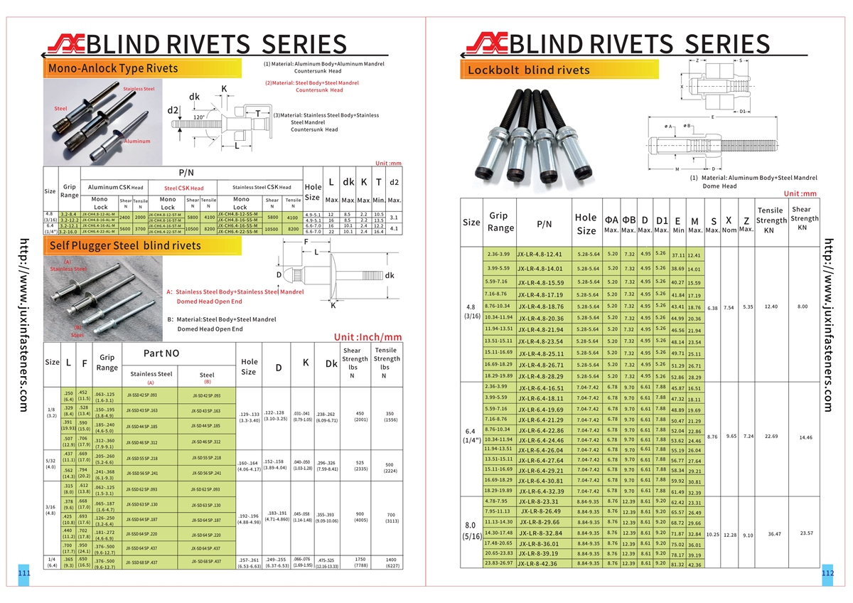
14. Technical Drawings and Catalog Reference
Please refer to the applicable product drawing and specification for detailed technical information.
Catalog Reference: Pages 111–112
The specification should be used to confirm:
Rivet diameter
Rivet length
Grip range
Domed head diameter
Head height
Installation hole diameter
Body material
Mandrel material
External locking construction
Mandrel break-position requirements
Dimensional tolerances
Mechanical ratings, where available
Installation tooling requirements
This page provides preliminary product and engineering guidance.
Final approval should rely on confirmed technical drawings, applicable specifications, and required application testing.
15. Frequently Asked Questions
What are externally locked structural blind rivets?
They are blind fasteners incorporating an externally identifiable mechanical locking feature intended to retain the mandrel after installation.
What is the difference between external lock and internal lock blind rivets?
An external lock is visible or identifiable at the installed rivet head. An internal lock is concealed within the fastener construction.
Why is mandrel retention important?
The retained mandrel can contribute to structural performance, while positive retention helps reduce the risk of loose stem components.
Are these rivets available in steel and stainless steel?
This JUXIN product series includes steel body/steel mandrel and stainless steel body/stainless steel mandrel configurations.
Do these rivets have a domed head?
Yes. The described product series uses a domed head rather than a countersunk head.
Can these rivets be installed from one side?
Yes. Blind rivets are designed for installation when only one side of the assembly is accessible.
Do externally locked blind rivets require special tools?
Certain designs require dedicated installation nosepieces to form the locking feature correctly. Tool compatibility must be confirmed.
Does a visible external lock guarantee correct installation?
No. The installed locking feature must meet the specified acceptance criteria, and the complete joint must satisfy the engineering requirements.
Are these rivets suitable for vibration-resistant assemblies?
They may be considered for demanding applications involving vibration, subject to verified product performance and joint validation.
Are externally locked structural blind rivets waterproof?
Not necessarily. Sealing performance depends on the specific product and joint design and requires separate verification.
Are these rivets interchangeable with other structural blind rivets?
Not automatically. Diameter, grip range, head geometry, mandrel construction, mechanical performance, and installation tooling must all be evaluated.
Can JUXIN support custom OEM specifications?
JUXIN welcomes drawing-based inquiries for custom dimensions, materials, finishes, packaging, and production requirements, subject to engineering and manufacturing review.
16. Request a Quotation — External Lock Structural Blind Rivets
JUXIN FASTENERS supplies industrial fastening solutions for international OEM manufacturers, equipment builders, structural engineers, design engineers, purchasing managers, sourcing teams, supply chain managers, and production managers.
For an accurate quotation, please provide:
Required rivet diameter
Minimum and maximum grip thickness
Body and mandrel materials
Material grades
External locking requirements
Installation hole diameter and tolerance
Joint material and thickness
Mechanical performance requirements
Surface treatment requirements
Installation tooling information
2D drawings or 3D CAD models
Sample or production quantity
Estimated annual demand
Packaging and delivery requirements
Our team can review your requirements and coordinate technical and commercial clarification for your OEM project.
Email: info@juxinfasteners.com
Website: www.juxinfasteners.com
JUXIN FASTENERS — Industrial Fasteners and Custom OEM Fastening Solutions
Product Packaging
Packaging Standard
At Juxin Fasteners, we apply standardized export packaging to ensure product protection, traceability, and compliance with international logistics requirements.
1. Standard Export Packaging
Unless otherwise specified, all products will be packed according to our factory standard export packaging, which includes:
Moisture-resistant inner protection
Poly bag or small box packing as required
Reinforced export cartons
Clear labeling with part number, specification, batch number, and quantity
Palletizing for sea or air shipment when necessary
Our standard packaging is designed to ensure safe transportation, efficient warehousing, and long-distance international shipping.
2. Customized Packaging Options
We also provide customized packaging solutions according to customer requirements, including but not limited to:
Private labeling
Customized barcodes
Specific carton dimensions
Retail packaging
Special pallet configuration
Customer-specific marking and identification
So that you know, customized packaging may involve additional costs and extended lead time depending on the complexity of the requirements.
3. Compliance & Quality Assurance
All packaging processes are controlled under our ISO 9001 quality management system to ensure consistency, traceability, and product integrity throughout the supply chain.
Product Pictures
Contact Us
Tel.:
+86 020 8621 0320
+86 020 3121 6067
E-mail:
Technical Support:
Navigation
SEND INQUIREY