Call Us
+86 136 6007 9809
Call Us
+86 136 6007 9809

Brass threaded inserts for plastics provide durable, reusable metal threads in injection-molded and other thermoplastic components where direct plastic threads may not provide the required assembly durability, serviceability, or resistance to repeated tightening.
Product Specification
Brass threaded inserts for plastics provide durable, reusable metal threads in injection-molded and other thermoplastic components where direct plastic threads may not provide the required assembly durability,
serviceability, or resistance to repeated tightening.
These precision fastening components are commonly used in electronic enclosures, automotive interior assemblies, electrical equipment,
telecommunications housings, industrial machinery, appliances, and engineered plastic components.
For OEM design engineers, purchasing managers, supply chain professionals, and production managers, selecting the correct brass threaded insert involves more than choosing a nominal thread size.
The insert geometry, thermoplastic material, receiving-hole dimensions, installation process, mechanical loading, environmental conditions, and production consistency all influence the reliability of the finished assembly.
JUXIN FASTENERS supplies industrial fastening components for international OEM applications, including threaded insert solutions for plastic assemblies and drawing-based custom fastening requirements.
This technical guide examines brass threaded insert designs, thermoplastic boss engineering, heat-set and ultrasonic installation methods, mechanical retention, material selection,
manufacturing quality, common installation defects, and international OEM procurement considerations.
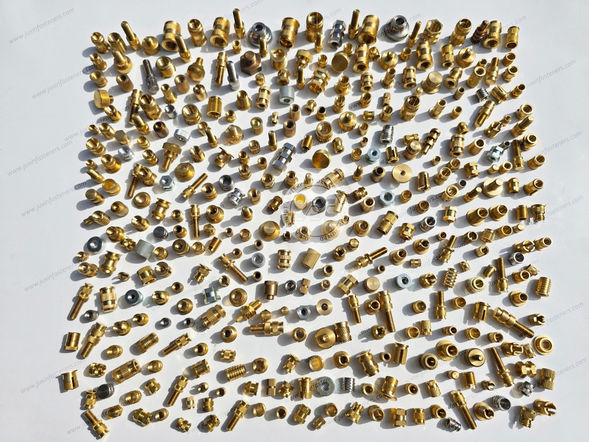
Different brass threaded insert designs are developed for different installation processes, plastic materials, and mechanical requirements.
The external geometry of an insert influences how the surrounding polymer flows, deforms, and mechanically engages with the insert during and after installation.
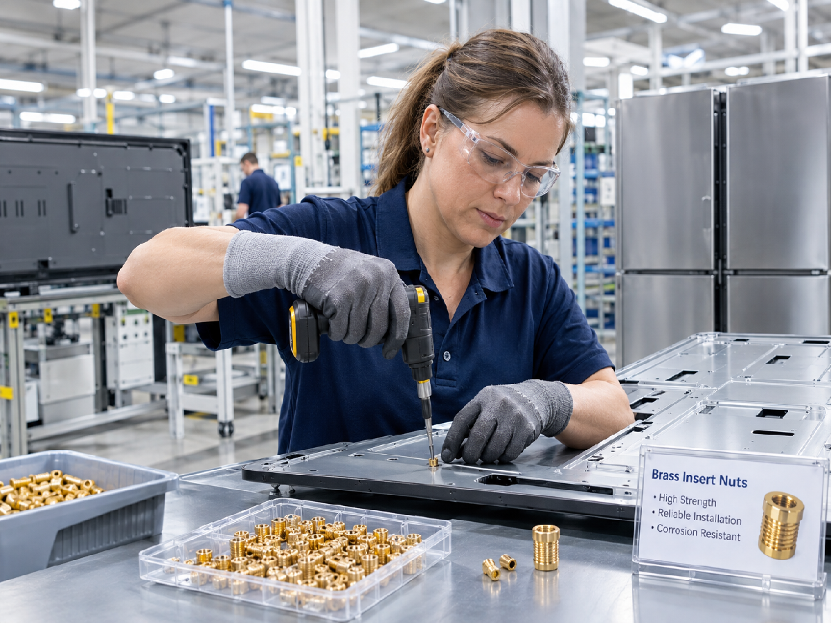
Heat-set brass threaded inserts are designed for installation into thermoplastic components using controlled heat and insertion force.
During installation, a heated tool transfers thermal energy to the insert, softening the surrounding thermoplastic material.
As the insert advances into the receiving hole, the softened polymer flows around the external knurls and undercuts.
After cooling, the polymer solidifies around these features, creating mechanical resistance to axial extraction and rotation.
Typical design characteristics include:
External knurling or grooves for mechanical engagement.
Internal threads suitable for repeated screw assembly.
External geometry designed for controlled plastic flow.
Installation dimensions matched to the selected thermoplastic.
Configurations suitable for manual, semi-automated, or automated installation.
Heat-set inserts are frequently considered for plastic electronic housings, automotive interior components, industrial equipment, and other assemblies requiring reusable metal threads.
Ultrasonic insertion uses high-frequency mechanical vibration and controlled insertion force to generate localized heating at the interface between the insert and the thermoplastic material.
As the surrounding polymer softens, the insert advances into the receiving hole. The plastic then cools and mechanically engages with the insert's external features.
Ultrasonic insertion can be suitable for production environments where equipment compatibility, process repeatability, and assembly efficiency are important.
However, ultrasonic compatibility must be evaluated for the specific insert geometry, polymer grade, installation equipment, and process conditions.
Not every heat-set insert is automatically suitable for ultrasonic installation.
Tapered threaded inserts incorporate an entry geometry that can assist alignment during installation.
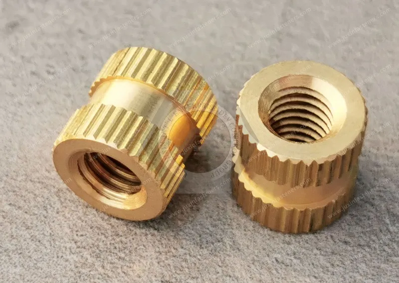
Knurled inserts use external surface features to improve mechanical engagement with the surrounding plastic.
Common external features include straight knurls, diamond knurls, diagonal knurls, grooves, and combinations of knurled regions and undercuts.
The appropriate geometry depends on the intended installation process, available boss dimensions, required axial retention, and resistance to rotation.
A more aggressive knurl pattern does not necessarily provide better performance in every application. Excessive interference may damage the surrounding plastic or introduce undesirable residual stress.
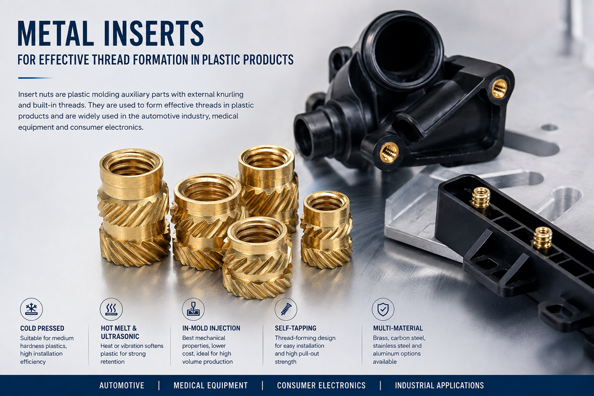
Molded-in inserts are positioned inside the injection mold before molten plastic is introduced.
The plastic solidifies around the insert, creating a mechanically retained threaded connection.
This method can be considered when the component design and production process support accurate insert positioning during molding.
Molded-in inserts may require different external geometries and dimensional controls from post-installed heat-set or ultrasonic inserts.
OEM engineers should identify the intended installation method before finalizing the insert drawing.
The plastic boss surrounding a threaded insert is a critical structural feature of the assembly.
Even a precisely manufactured brass insert may fail if the surrounding boss does not provide sufficient material for retention or if installation introduces excessive mechanical stress.
Boss wall thickness must be evaluated in relation to the insert geometry, receiving-hole dimensions, polymer properties, and expected service loads.
Important engineering variables include:
Insert external diameter and knurl configuration.
Receiving-hole diameter.
Plastic resin grade.
Glass-fiber or mineral reinforcement.
Installation temperature and force.
Required pull-out and torque-out resistance.
Operating temperature.
Environmental exposure.
Nearby ribs, walls, and molded structural features.
For a cylindrical boss with a concentric receiving hole, the nominal radial wall thickness can be calculated as:
W = (D_b − D_h) / 2
Where:
W = Nominal radial boss wall thickness
D_b = Boss outer diameter
D_h = Receiving-hole diameter
For example, a boss with an outer diameter of 10 mm and a receiving-hole diameter of 5 mm has a nominal radial wall thickness of 2.5 mm.
This equation describes the boss geometry. It does not establish a minimum mechanically acceptable wall thickness.
The required minimum wall thickness must be determined through insert-specific design recommendations, polymer characteristics, and appropriate engineering validation.
Universal boss diameter multipliers should not be applied indiscriminately across ABS, PC, PA6, PA66, POM, and glass-filled engineering plastics.
The receiving-hole diameter influences the amount of plastic displaced during installation and the resulting mechanical engagement.
An oversized hole may reduce retention because insufficient polymer engages with the insert's external features.
An undersized hole may increase insertion force, deform the boss, or cause cracking.
Receiving-hole dimensions should be established using the selected insert's technical drawing and validated installation requirements.
For injection-molded components, engineers should also consider molding shrinkage, hole taper, dimensional variation, and the influence of process conditions.
Blind-hole applications require sufficient depth to accommodate the complete insert and any displaced plastic.
Inadequate bottom clearance may prevent full insertion or create stress concentrations at the bottom of the boss.
The required clearance depends on the insert geometry, installation method, and receiving-hole design.
A fixed clearance value should not be assumed for all brass threaded inserts.
Boss design should also consider:
Concentricity and perpendicularity.
Nearby ribs and reinforcement features.
Molded wall-thickness transitions.
Sink marks and cooling behavior.
Weld lines and local material weakness.
Edge distances.
Molded-in stresses.
Available assembly space.
These factors become particularly important in compact electronic enclosures, thin-wall plastic housings, and components subjected to repeated assembly.
Heat-set and ultrasonic insertion are both established methods for installing suitable metal threaded inserts into thermoplastic components.
However, neither process should automatically be described as faster, stronger, or more reliable under all conditions.
The correct selection depends on the insert geometry, polymer characteristics, production equipment, and validated assembly process.
| Engineering Factor | Heat-Set Insertion | Ultrasonic Insertion |
|---|---|---|
| Energy transfer | Conductive heating | High-frequency mechanical vibration |
| Plastic softening | Heat transferred through the insert | Localized heating at the interface |
| Typical equipment | Thermal insertion press | Ultrasonic insertion equipment |
| Insert geometry | Heat-insertion-compatible design | Ultrasonic-compatible design |
| Main process variables | Temperature, force, travel, dwell time | Amplitude, force, travel, time, energy |
| Potential defects | Overheating, incomplete seating, plastic degradation | Excessive stress, plastic damage, incomplete seating |
| Production integration | Manual to automated systems | Semi-automated to automated systems |
| Quality verification | Seating, alignment, retention, dimensional checks | Seating, alignment, retention, dimensional checks |
For heat-set insertion, the installation temperature must be compatible with the thermoplastic material and insert design.
Insufficient heating may prevent adequate plastic flow around the external features.
Excessive heating may degrade the polymer, deform the surrounding component, or produce inconsistent retention.
Insertion force, travel, dwell time, and cooling conditions should be established through process trials.
Ultrasonic insertion requires suitable equipment settings and insert geometry.
Important variables may include vibration amplitude, insertion force, energy input, travel distance, and hold conditions.
Incorrect settings may result in incomplete seating, localized material damage, or inconsistent mechanical retention.
The process should be validated using the actual production resin and representative molded components.
For high-volume OEM assembly, production managers should evaluate more than the nominal insertion cycle time.
Relevant manufacturing considerations include:
Installation repeatability.
Equipment compatibility.
Operator handling requirements.
Assembly cycle-time variation.
Scrap and rework rates.
Tooling maintenance.
Insert feeding and orientation.
Installation depth control.
Total assembly cost.
The preferred installation method is the one that consistently satisfies the engineering requirements within the available production process.
The mechanical performance of a brass threaded insert depends on the complete installed assembly rather than the insert alone.
OEM engineers commonly evaluate axial retention, rotational retention, and the performance of the assembled screw joint.
Pull-out resistance describes the axial force required to extract an installed insert from the surrounding plastic under defined test conditions.
Important influencing factors include:
External knurl geometry.
Effective engagement length.
Polymer shear strength.
Receiving-hole dimensions.
Installation quality.
Test temperature.
Loading direction and rate.
Environmental aging.
The surrounding polymer must provide sufficient mechanical engagement with the insert's external features.
An insert with deeper knurls does not necessarily produce higher retention in every material. Excessive interference can damage the boss and reduce assembly reliability.
Pull-out performance should be evaluated using the actual or representative plastic component.
Torque-out resistance describes the resistance of an installed insert to rotation within the surrounding plastic.
It is particularly relevant when screws are repeatedly installed, tightened, or removed.
Torque-out resistance is influenced by the external geometry, polymer engagement, insert diameter, and installation process.
It must not be confused with the allowable tightening torque of the assembled screw joint.
The allowable assembly torque may be limited by the screw, internal thread, insert retention, surrounding polymer, or other structural features.
Thread stripping occurs when the mating threads can no longer support the applied load.
Other possible failure modes include:
Insert rotation.
Axial pull-out.
Plastic boss cracking.
Plastic creep.
Stress relaxation.
Loss of clamp load.
Insert misalignment.
Damage from excessive installation force.
Damage from unsuitable installation temperature.
Each failure mode should be evaluated separately.
For critical OEM applications, prototype assemblies should undergo appropriate testing under representative installation and service conditions.
Brass is commonly selected for threaded inserts because suitable alloys offer good machinability, dimensional consistency, and useful mechanical properties for threaded components.
However, the brass grade must be selected according to the customer's drawing and application requirements.
C3604 is a recognized free-machining brass designation used in industrial machining applications.
Other brass grades may also be specified depending on regional material standards, manufacturing requirements, and application conditions.
C3604 should not be assumed to be the material of every brass threaded insert.
For custom OEM orders, the required alloy designation should be clearly identified and confirmed before production.
ABS is used in electronic housings, appliances, and other molded components.
Insert selection should consider the specific ABS grade, boss geometry, installation process, and operating temperature.
Polycarbonate is used in applications requiring suitable impact resistance and dimensional characteristics.
Installation conditions should be evaluated carefully because localized stresses may affect the surrounding molded component.
PA6 and PA66 are used in automotive, electrical, and industrial mechanical components.
Their mechanical properties and dimensions can be influenced by moisture absorption and temperature.
These characteristics should be considered when designing the receiving hole and evaluating long-term retention.
POM is used in dimensionally controlled mechanical components and low-friction applications.
The specific resin grade, insertion process, and expected mechanical loads must be evaluated before selecting an insert design.
Glass-fiber-reinforced polymers may offer increased stiffness and strength compared with unfilled materials.
However, reinforcement can also affect local deformation behavior, stress distribution, and installation performance.
Insert geometry and boss dimensions should be validated for the actual reinforced polymer grade.
Brass and thermoplastics have different coefficients of thermal expansion.
Temperature changes may generate differential movement and stress within the assembled component.
For applications involving repeated thermal cycling, engineers should consider:
Polymer expansion and contraction.
Moisture absorption.
Material aging.
Creep and stress relaxation.
Mechanical loading.
Environmental exposure.
Long-term joint performance should be evaluated according to the actual operating conditions.
International OEM projects may specify metric or inch-based internal threads.
Common metric designations include M3, M4, M5, and M6, subject to the actual product specification and manufacturing availability.
An M4 × 0.7 thread has:
Nominal major diameter: 4 mm
Approximate inch equivalent of nominal diameter: 0.1575 in
Thread pitch: 0.7 mm
This inch conversion is a dimensional reference only.
UNC and UNF are Unified thread series commonly referenced in North American engineering drawings.
They use thread designations and pitch systems that differ from ISO metric threads.
BSW and BSF are Whitworth thread systems used in certain British and legacy industrial applications.
Their thread geometry differs from Unified and ISO metric thread systems.
Metric, UNC, UNF, BSW, and BSF threads are not directly interchangeable simply because their nominal diameters are similar.
Engineers must verify thread designation, pitch, thread form, tolerance class, and engagement requirements.
Applicable engineering references may include ISO metric thread standards, ASME B1.1 for Unified threads, and relevant British thread standards.
Custom inch-thread insert requirements should be submitted with a drawing for manufacturing feasibility review.
For high-volume OEM production, consistent insert geometry and controlled installation are important to assembly repeatability.
The inspection requirements should be defined according to the product drawing, manufacturing process, and customer's quality expectations.
Relevant inspection characteristics may include:
Internal thread designation and gauging.
Insert outer diameter.
Overall length.
External knurl dimensions.
Chamfer and entry geometry.
Material identification.
Surface condition.
Burrs and machining defects.
Packaging and identification requirements.
After installation, production inspection may consider:
Installation depth.
Insert alignment.
Perpendicularity.
Surrounding boss condition.
Visible cracks or deformation.
Thread accessibility.
Functional assembly checks.
Where specified, pull-out and torque-out tests can be used to evaluate installed insert retention.
Test methods, acceptance criteria, sample quantities, and environmental conditions should be agreed for the application.
Generic performance values should not replace product-specific testing.
OEM purchasing requirements may include dimensional inspection reports, material identification, lot records, or other agreed documentation.
Availability of specific certificates, test reports, or quality approval documents must be confirmed for the individual product and order.
No certification or testing capability should be assumed without verification.
Brass threaded inserts can provide reusable mounting threads for plastic equipment housings, access panels, electronic assemblies, and internal supports.
Design considerations include compact boss dimensions, repeated maintenance access, dimensional stability, and compatibility with the selected polymer.
Automotive interior assemblies may use threaded inserts where plastic components require reusable screw connections.
Potential applications include interior trim assemblies, electronic module housings, and other engineered plastic components.
OEM engineers should evaluate vibration, thermal cycling, polymer aging, and assembly requirements.
Threaded inserts may be considered for plastic electrical equipment housings, mounting features, and serviceable assemblies.
Electrical insulation, creepage and clearance distances, grounding, and thermal requirements must be evaluated at the complete equipment design level.
A brass threaded insert alone does not establish electrical compliance.
Reusable metal threads can support maintenance and assembly requirements in molded machine covers, control housings, and industrial accessories.
Relevant considerations include service frequency, mechanical loading, operating temperature, and environmental exposure.
Threaded inserts may be used in plastic housings and structural mounting features where repeated screw assembly is required.
Production managers should evaluate installation repeatability, assembly cost, and long-term serviceability.
Threaded inserts may be considered for suitable plastic equipment housings and serviceable assemblies.
Any sterilization, chemical cleaning, biocompatibility, or regulated medical application requirements must be separately validated.
Possible causes:
Oversized receiving hole.
Insufficient polymer engagement.
Unsuitable knurl geometry.
Incorrect installation conditions.
Excessive assembly torque.
Recommended engineering review:
Verify the insert drawing, receiving-hole dimensions, polymer grade, installation process, and specified assembly torque.
Possible causes:
Excessive insertion interference.
Inadequate boss geometry.
Brittle or unsuitable polymer.
Excessive installation force.
Incorrect thermal or ultrasonic settings.
Recommended engineering review:
Examine the boss design, polymer characteristics, and installation process before changing the insert dimensions.
Possible causes:
Insufficient hole depth.
Inadequate bottom clearance.
Insert misalignment.
Incorrect tooling.
Unsuitable installation parameters.
Recommended engineering review:
Check the approved drawing, installation depth, alignment, and process settings.
Possible causes:
Insufficient engagement length.
Inappropriate external geometry.
Inadequate polymer strength.
Installation defects.
Service loads exceeding validated capability.
Recommended engineering review:
Evaluate the complete load path, boss geometry, insert design, and actual service conditions.
Possible causes:
Incorrect thread designation.
Cross-threading.
Insufficient thread engagement.
Excessive tightening torque.
Damaged mating screws.
Recommended engineering review:
Confirm thread compatibility, screw alignment, thread quality, and assembly torque requirements.
Custom brass threaded inserts are frequently specified when standard catalog dimensions do not match the available installation space, thread requirements, or mechanical design.
Drawing-based sourcing allows OEM buyers to define the component according to the actual assembly requirements.
Relevant dimensions may include:
Internal thread designation.
Insert outer diameter.
Overall length.
Knurl pattern.
Groove dimensions.
Chamfer geometry.
Entry taper.
Critical dimensional tolerances.
The RFQ should identify the required brass grade or acceptable alternatives.
If a specific alloy is mandatory, the exact material designation should be stated.
The intended installation method should be specified as heat-set, ultrasonic, or molded-in.
Different methods may require different external geometries and process conditions.
The engineering package should identify:
Polymer grade.
Receiving-hole diameter.
Boss outer diameter.
Hole depth.
Available installation space.
Reinforcement content, where relevant.
Any required pull-out resistance, torque-out resistance, repeated assembly performance, or environmental testing should be stated.
Numerical targets and validation methods should be agreed before production qualification.
Commercial RFQs should include:
Prototype or sample quantity.
Initial production order quantity.
Estimated annual usage.
Target delivery schedule.
Destination market.
Packaging requirements.
Drawing revision information.
These details help suppliers evaluate manufacturing feasibility, quotation requirements, and production planning.
For international OEM purchasing teams, the lowest quoted unit price does not necessarily represent the lowest total procurement cost.
A threaded insert that causes installation defects, excessive rework, or inconsistent retention may create additional manufacturing expenses.
Procurement managers and supply chain professionals should consider:
Dimensional consistency.
Material specification control.
Compatibility with existing installation equipment.
Drawing revision management.
Quality inspection requirements.
Packaging and handling.
Production quantity planning.
Delivery requirements.
Engineering change communication.
Total assembly and rework costs.
Production managers should also assess installation repeatability, equipment utilization, cycle-time consistency, and defect prevention.
For long-term OEM programs, the selected component and supplier should be evaluated against documented technical, quality, commercial, and delivery requirements.
A heat-set insert is installed into an existing thermoplastic component using controlled heat and force.
A molded-in insert is positioned in the injection mold before the plastic is introduced.
Their external geometry, installation process, and dimensional requirements may differ.
Suitable threaded inserts can be considered for PA66 and ABS components.
However, the resin grade, boss geometry, installation conditions, and mechanical requirements must be evaluated.
Not necessarily.
Some insert designs may support multiple installation methods, but compatibility must be confirmed through technical specifications and process validation.
Pull-out strength is established through suitable testing of the installed insert in the actual or representative plastic component.
Generic brass material properties alone cannot determine the final retention force.
Custom inch-thread requirements can be submitted for engineering and manufacturing review.
Actual availability depends on the requested drawing, dimensions, material, and order quantity.
Possible causes include insufficient mechanical engagement, oversized receiving holes, unsuitable external geometry, improper installation, or excessive assembly torque.
A technical drawing, thread designation, insert dimensions, material requirements, polymer information, installation method, order quantity, and delivery requirements provide a practical starting point.
JUXIN FASTENERS supports international B2B sourcing inquiries for industrial fastening components, including threaded inserts for plastic assemblies and drawing-based OEM fastening requirements.
Whether your project involves electronic enclosures, automotive plastic components, electrical equipment, industrial machinery, or custom injection-molded assemblies,
clearly defined technical and purchasing requirements help establish an accurate quotation.
Please provide the following information with your RFQ:
2D engineering drawing or 3D CAD model, where available.
Internal thread designation, pitch, and insert dimensions.
Required brass material grade.
Surface treatment requirements, if applicable.
Plastic resin grade and receiving-hole geometry.
Intended installation method.
Mechanical performance and inspection requirements.
Prototype quantity and production order quantity.
Estimated annual purchasing volume.
Target delivery schedule and destination.
Our team can review the submitted specifications and confirm the applicable sourcing, manufacturing feasibility, and quotation requirements.
Company: JUXIN FASTENERS
Website: www.juxinfasteners.com
Email: info@juxinfasteners.com
Contact JUXIN FASTENERS with your engineering drawings, product specifications, and purchasing requirements to request a quotation for brass threaded inserts and related OEM fastening components.
Product Packaging
Packaging Standard
At Juxin Fasteners, we apply standardized export packaging to ensure product protection, traceability, and compliance with international logistics requirements.
1. Standard Export Packaging
Unless otherwise specified, all products will be packed according to our factory standard export packaging, which includes:
Moisture-resistant inner protection
Poly bag or small box packing as required
Reinforced export cartons
Clear labeling with part number, specification, batch number, and quantity
Palletizing for sea or air shipment when necessary
Our standard packaging is designed to ensure safe transportation, efficient warehousing, and long-distance international shipping.
2. Customized Packaging Options
We also provide customized packaging solutions according to customer requirements, including but not limited to:
Private labeling
Customized barcodes
Specific carton dimensions
Retail packaging
Special pallet configuration
Customer-specific marking and identification
So that you know, customized packaging may involve additional costs and extended lead time depending on the complexity of the requirements.
3. Compliance & Quality Assurance
All packaging processes are controlled under our ISO 9001 quality management system to ensure consistency, traceability, and product integrity throughout the supply chain.
Product Pictures
Contact Us
Tel.:
+86 020 8621 0320
+86 020 3121 6067
E-mail:
Technical Support:
Navigation
SEND INQUIREY