Call Us
+86 136 6007 9809
Call Us
+86 136 6007 9809

Injection-molded plastic components are widely used in automotive lighting, electronics, electrical equipment, appliances, medical equipment and industrial products.
The plastic housing may be lightweight, corrosion resistant and geometrically complex.
The threaded joint inside it creates a different engineering problem.
Product Specification
Injection-molded plastic components are widely used in automotive lighting, electronics, electrical equipment, appliances, medical equipment and industrial products.
The plastic housing may be lightweight, corrosion resistant and geometrically complex.
The threaded joint inside it creates a different engineering problem.
A screw driven directly into plastic can be suitable for some assemblies, particularly where the joint is assembled only once or a limited number of times.
But applications requiring reusable machine threads, repeated servicing, higher tightening loads or controlled assembly may benefit from a metal threaded insert installed into the plastic component.
JUXIN FASTENERS supplies and supports threaded insert solutions for plastic, including:
Knurled brass threaded inserts
Heat-set threaded inserts
Heat-staking inserts
Ultrasonic threaded inserts
Mold-in threaded inserts
Straight-knurled inserts
Diagonal-knurled inserts
Diamond-knurled inserts
Flanged threaded inserts
Tapered threaded inserts
Drawing-based custom threaded inserts
Stainless steel threaded inserts, including 303 stainless steel configurations for suitable applications
Applications include:
Automotive lighting housings
Automotive electronic modules
Electrical enclosures
Control systems
Consumer and industrial electronics
Appliance housings
Medical equipment housings
Communication equipment
Industrial plastic components
The correct insert should not be selected by thread size alone.
The insert, polymer, plastic boss and installation process form one fastening system.
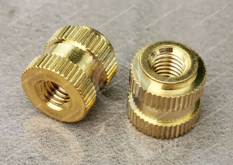
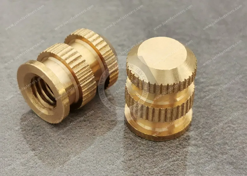
A knurled brass threaded insert is a metal component installed into a plastic part to provide a reusable internal machine thread.
External features can include:
Straight knurls
Diagonal knurls
Opposing knurl patterns
Diamond-style knurls
Annular grooves
Undercuts
Tapered lead-in geometry
Flanges
These external features create mechanical engagement between the insert and surrounding polymer.
The internal thread then accepts a conventional mating screw.
Depending on the insert geometry and plastic application, installation can be performed by methods such as:
Heat setting
Heat staking
Ultrasonic insertion
Mold-in installation
The correct method depends on the insert design and polymer.
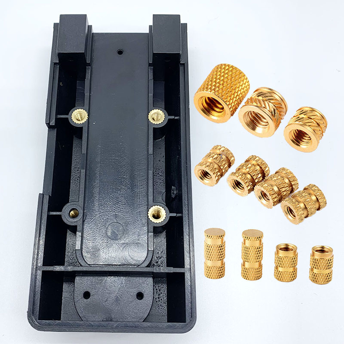
Brass is commonly used for threaded inserts because it combines characteristics useful for plastic fastening applications.
Depending on the specified alloy and insert design, these can include:
Machinability
Dimensional control
Corrosion resistance in many equipment environments
Thermal conductivity useful for heat insertion
Suitability for detailed external knurl geometry
Reliable internal machine threads
However, the phrase brass insert is not a complete engineering specification.
The application still needs to define:
Brass alloy where required
Thread
Insert length
Outside diameter
Knurl geometry
Installation method
Plastic material
Boss geometry
Mechanical requirements
A common design mistake is to finish the plastic boss first and choose the threaded insert later.
That reverses the engineering sequence.
The insert affects:
Pilot-hole diameter
Boss outside diameter
Boss wall thickness
Boss depth
Insert depth
Material displacement
Required plastic flow
Pull-out performance
Torque-out performance
Therefore:
Insert selection should ideally occur before the plastic mold design is frozen.
Changing the insert after mold tooling has been completed can require boss or hole modifications.
Both fastening approaches have valid applications.
Can be appropriate where:
Assembly cycles are limited
Cost and component count are priorities
The polymer and screw are designed as a system
Service requirements are limited
Can be appropriate where:
A machine screw is required
The joint will be opened repeatedly
Reusable threads are important
Higher thread durability is required
Assembly torque needs better control
The OEM wants a metal thread interface
A threaded insert is therefore not automatically necessary for every plastic boss.
The choice should follow the joint requirement.
Heat-set inserts are installed by heating the metal insert and transferring thermal energy into the surrounding thermoplastic.
The softened polymer flows around the insert's external retention geometry.
After cooling, the polymer forms a mechanical interlock around the insert.
The process depends on more than temperature.
Important variables can include:
Insert geometry
Insert temperature
Heating method
Installation speed
Axial force
Dwell time
Polymer type
Boss geometry
Final insertion depth
For this reason:
There is no universal heat-set temperature suitable for every brass insert and every thermoplastic.
The installation window should be established for the actual insert and polymer combination.
Ultrasonic insertion uses high-frequency mechanical energy to generate localized heating at the insert-plastic interface.
The softened polymer then flows around the insert retention features.
Potential advantages can include rapid installation and localized heating.
But successful ultrasonic insertion depends on:
Insert geometry
Polymer
Boss design
Ultrasonic equipment
Horn alignment
Amplitude
Pressure
Insertion depth
A heat-set insert should not automatically be assumed to be optimized for ultrasonic installation.
The intended installation method should be considered when selecting the insert geometry.
Mold-in inserts are positioned inside the mold before plastic injection.
The polymer is molded around the insert.
This approach eliminates a separate post-molding insertion operation, but introduces different manufacturing requirements.
Important considerations include:
Insert positioning
Core-pin or fixture design
Insert retention during molding
Injection pressure
Polymer flow
Flash control
Thread protection
Insert orientation
Mold-cycle handling
A mold-in insert is therefore not simply a heat-set insert placed into the mold.
The geometry and manufacturing process should be reviewed for mold-in use.
Heat-set inserts are installed after molding.
Mold-in inserts are incorporated during molding.
This changes where dimensional risk occurs.
With heat setting, important risks include:
Incorrect insertion temperature
Excessive insertion force
Wrong installation depth
Boss cracking
Poor polymer flow
With mold-in installation, important risks include:
Insert movement during injection
Incorrect positioning
Plastic entering the thread
Mold handling complexity
Orientation errors
The same thread requirement can therefore lead to two very different production systems.
Straight knurls create axial external features along the insert body.
Depending on the complete insert design, they can contribute to engagement with the surrounding plastic.
Their suitability depends on:
Polymer
Installation method
Groove geometry
Insert diameter
Insert length
Boss geometry
A straight-knurled insert should not automatically be described as optimized for every pull-out or torque requirement.
Diagonal knurling creates angled engagement features around the insert body.
These geometries can be used to develop resistance against movement within the surrounding polymer.
Depending on the design, diagonal or opposing knurl patterns may help create mechanical resistance to both axial and rotational loading.
But performance cannot be predicted from the word “diagonal” alone.
The actual:
Knurl angle
Knurl depth
Outside diameter
Groove structure
Insert length
Polymer
all contribute to the joint.
Crossed or diamond-style knurl patterns create multiple directions of external surface geometry.
These designs can increase the mechanical interaction between the insert and polymer.
However:
More aggressive knurling does not automatically mean a better insert.
A larger or deeper knurl requires the polymer to accommodate more insert geometry.
If the boss is too thin or the pilot hole is poorly matched, aggressive external features can increase local stress.
The correct knurl pattern should balance:
Pull-out resistance
Torque-out resistance
Polymer displacement
Boss integrity
Installation process
It is tempting to assume:
Deeper knurl = stronger insert.
That is incomplete.
An aggressive knurl may create more mechanical interlock, but the surrounding polymer must flow around that geometry without
creating unacceptable residual stress or damaging the boss.
A useful insert design therefore seeks sufficient mechanical interlock without unnecessarily overloading the plastic structure.
The correct target is not maximum knurl depth.
It is a stable insert + polymer + boss + installation process.
A flanged insert adds a larger shoulder or collar at one end.
Depending on the joint design, the flange can provide:
A defined seating surface
Axial location
Increased bearing area
Installation-depth control
Resistance to movement in a particular loading direction
However, the flange also occupies space.
Designers should consider:
Counterbore or seating geometry
Component clearance
Clamp direction
Boss diameter
Final surface position
A flange is useful when the assembly architecture benefits from it, not simply because it makes the insert larger.
Tapered inserts can help guide installation into a prepared plastic hole.
JUXIN FASTENERS also works with tapered threaded insert configurations, including stainless steel insert applications.
Tapered geometry can affect:
Initial alignment
Polymer displacement
Insertion behavior
Final seating
The pilot hole should be designed for the specific insert geometry rather than treating every tapered insert as interchangeable.
A plastic boss can crack during insertion when the insert, hole and boss geometry are poorly matched.
Possible contributors include:
Pilot hole too small
Boss wall too thin
Insert outside diameter too large
Aggressive knurl geometry
Incorrect insertion temperature
Excessive insertion force
Polymer condition
Molded-in residual stress
The correct response is not automatically to make the boss thicker.
The complete geometry should be reviewed.
Two bosses with the same outside diameter may perform differently because of:
Pilot-hole diameter
Insert diameter
Boss height
Base fillet
Rib support
Polymer
Fiber reinforcement
Mold flow
Weld lines
Installation process
This means simple rules such as “boss diameter should always equal X times insert diameter” can be useful as preliminary guidance but should not replace application validation.
Two common insert failure modes are frequently confused.
Axial force pulls the insert out of the plastic boss.
Rotational force causes the insert to rotate within the plastic.
An insert geometry that performs well against pull-out does not automatically provide identical resistance to rotation.
Different external features can influence these two failure modes differently.
Therefore:
A single generic “insert strength” value is not enough.
The mechanical requirement should match the actual assembly load.
Pull-out and torque-out are not the only considerations.
When the mating screw is tightened, the joint creates clamp load.
That load passes through:
Screw
Insert
Plastic structure
Mating component
Excessive tightening can damage the plastic even if the insert itself remains securely retained.
The correct assembly torque should therefore consider the entire plastic joint.
This is an important distinction during validation.
An insert can remain firmly locked inside the boss while the surrounding plastic:
Cracks
Creeps
Deforms
Collapses under the mating component
Loses clamp load
Therefore, insert retention testing alone does not validate the complete bolted plastic joint.
Engineers should evaluate both:
insert retention and joint behavior.
Thermoplastics are viscoelastic materials.
Under sustained load, the plastic structure can deform over time.
Temperature can increase this effect.
This means clamp load in a plastic assembly may change even when:
The screw remains intact
The insert does not rotate
The insert does not pull out
For applications exposed to thermal cycling, the engineer should consider the behavior of the entire joint over time.
This is particularly relevant in:
Automotive lighting
Under-hood electronics
Electrical equipment
Appliances
Industrial electronics
Polyamide materials such as PA6 and PA66 are widely used in engineered plastic components.
Insert selection should consider:
Moisture conditioning
Operating temperature
Glass reinforcement
Boss geometry
Installation method
The phrase insert for nylon is not a complete specification.
PA6, PA66 and glass-filled variants can behave differently during insertion and service.
Glass-filled PA66 is common in structural plastic components.
Compared with unfilled polymer, glass reinforcement changes material behavior.
This can affect:
Material flow during insertion
Local stress
Boss design
Insertion window
Retention behavior
A heat-set process developed for unfilled PA66 should not automatically be transferred unchanged to PA66-GF.
The actual material grade should be included in the RFQ.
Polycarbonate is used in many electronic, lighting and equipment housings.
The insert installation process should avoid excessive local stress or thermal damage.
Important considerations include:
Boss dimensions
Insert geometry
Installation energy
Final insertion depth
Environmental requirements
For transparent or appearance-sensitive components, cosmetic effects around the boss may also matter.
ABS is widely used in equipment and electronics housings.
Heat-set and ultrasonic insert technologies may be considered depending on the component design.
The installation process should be developed around:
Actual ABS grade
Boss geometry
Insert geometry
Required joint load
Service cycles
Again, polymer name alone is insufficient for final process settings.
PBT and other thermoplastics can also use threaded insert systems.
Each material has different:
Softening behavior
Thermal characteristics
Stiffness
Reinforcement options
Creep behavior
The insert process should therefore follow the actual resin and application rather than a universal temperature chart.
Polypropylene presents a different material behavior from engineering polymers such as PA66 or PC.
Applications should consider:
Lower stiffness
Boss geometry
Insert retention
Service load
Temperature
The correct insert architecture may differ from one used in a rigid glass-filled engineering polymer.
Automotive headlamps, tail lamps and other lighting assemblies can contain:
Plastic housings
Electronic control modules
LED boards
Adjustment mechanisms
Brackets
Serviceable components
Threaded inserts can be used where the design requires reusable metal threads in molded plastic structures.
Important design considerations can include:
Thermal cycling
Vibration
Polymer grade
Insert position
Boss integrity
Screw tightening
Assembly sequence
A generic “automotive brass insert” does not define these requirements.
Electronic control modules and other vehicle electronics may combine:
Molded plastic enclosures
PCB assemblies
Metal covers
Connectors
Heat-management components
Threaded inserts can provide mounting points for:
Covers
Brackets
PCBs
Internal modules
External attachment features
Material and geometry should be selected according to the actual environment.
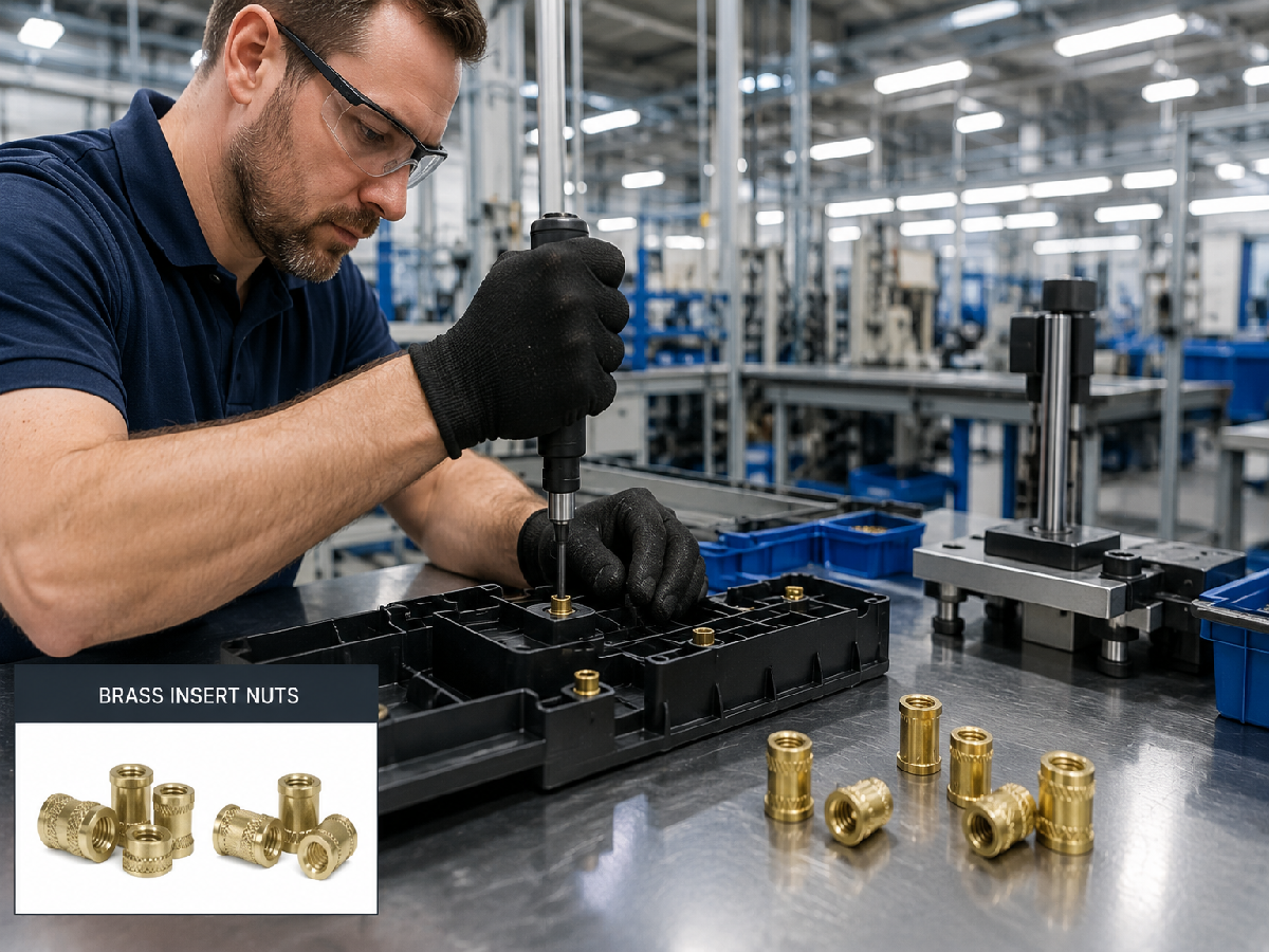
Brass inserts can be used in:
Power supplies
Control modules
Electrical switches
Communication equipment
Industrial electronics
Power distribution equipment
Instrument housings
For electrical equipment, designers should also consider whether the insert has any electrical function.
A brass insert should not automatically be treated as a grounding terminal.
Mechanical fastening and electrical bonding requirements should be defined separately.
Appliances and commercial equipment frequently use molded plastic components.
Potential insert applications include:
Service panels
Structural brackets
Motor mounts
Control assemblies
Handles
Hinges
Equipment covers
For repeatedly serviced assemblies, a metal insert can help preserve the threaded interface compared with repeatedly driving a screw directly into the same plastic thread.
Threaded inserts can also be used in non-implant medical equipment, including:
Diagnostic equipment
Laboratory instruments
Electronic medical equipment
Equipment carts
Control housings
Material, cleaning and documentation requirements should follow the OEM specification.
The presence of a brass insert inside medical equipment does not automatically make it a “medical-grade insert.”
Increasing insert length can increase the amount of polymer engaged by the insert.
But longer is not automatically better.
A longer insert may require:
Deeper boss
More plastic material
Different molding geometry
Greater insertion depth
More installation energy
If the boss does not have sufficient depth, selecting a longer insert can create new problems.
Insert length should follow the required mechanical performance and available plastic geometry.
It is misleading to optimize one dimension independently.
For example:
Increasing insert diameter may increase engagement but require a larger boss.
Increasing insert length may increase engagement but require more depth.
Increasing knurl aggressiveness may increase interlock but require more polymer flow.
The designer is balancing:
insert envelope + boss envelope + polymer behavior + required load + installation process.
This is why threaded inserts should be treated as engineered interfaces rather than commodity threaded bushings.
The pilot hole is one of the most important dimensions in a post-mold installed insert.
If the hole is too small:
Insertion force can increase
Polymer displacement increases
Boss stress can increase
If the hole is too large:
Polymer engagement may decrease
Retention may be reduced
Insert positioning may become less stable
The correct pilot hole depends on:
Insert geometry
Polymer
Installation method
Required performance
A universal hole size should not be assigned to a thread size.
For blind plastic bosses, hole depth must accommodate:
Insert length
Polymer displacement
Installation depth
Screw penetration where applicable
If the mating screw is too long, it can bottom out before the joint is correctly clamped.
This can create misleading torque readings.
A torque-controlled screwdriver may reach its target torque because the screw has bottomed, not because the joint has achieved the intended clamp condition.
This is an important failure mode in plastic assemblies.
If a screw bottoms inside the insert or boss, the driver may report a high torque.
That does not necessarily mean the joint is correctly clamped.
The same can occur if:
Threads are damaged
Galling or contamination increases friction
Screw length is incorrect
Components are misaligned
For automated assembly, torque data should therefore be interpreted together with joint geometry.
The final insert position can affect:
Mating-component seating
Clamp load
Cosmetic appearance
Screw engagement
Stack-up
An insert installed too high or too deep can create assembly problems even if its pull-out strength is acceptable.
For this reason, installation height or depth can be a critical inspection characteristic.
If an insert is installed at an angle, the mating screw may:
Start poorly
Cross-thread
Pull the component sideways
Create uneven loading
Installation tooling should therefore support appropriate alignment.
This becomes particularly important in:
Automated assembly
Small threads
Deep bosses
Multi-insert components
A housing may contain several threaded inserts.
Each insert can be dimensionally correct while the complete assembly still has alignment problems.
This occurs because the final pattern depends on:
Molded-hole position
Mold shrinkage
Insert installation position
Insert angle
Mating-part hole pattern
For multi-insert assemblies, engineers should evaluate the complete mounting pattern, not only each insert individually.
Certain polymers can be sensitive to combinations of:
Residual stress
Chemicals
Temperature
Mechanical load
Insert installation can contribute local stress if the boss geometry or process is unsuitable.
Chemical compatibility should therefore be considered when the component will contact:
Cleaners
Oils
Fuels
Process chemicals
Other application-specific fluids
The fastener alone cannot prevent environmental stress cracking.
Polymer selection and component design remain critical.
Brass provides useful corrosion resistance in many equipment environments, but the complete assembly should still be considered.
Possible issues include:
Moisture
Chemical exposure
Contact with dissimilar metals
Electrical requirements
Appearance requirements
If a specific brass alloy or corrosion requirement is mandatory, it should be included on the drawing or RFQ.
JUXIN FASTENERS should not substitute a generic brass description for a customer-specified material standard.
Brass is not the only insert material.
JUXIN FASTENERS also supports stainless steel threaded insert applications, including tapered 303 stainless steel heat-set insert configurations.
Good machinability is useful
Heat-transfer behavior supports the installation process
Complex knurl geometry is required
The application is compatible with brass
The OEM specifies stainless steel
Material compatibility requires it
Application-specific corrosion conditions favor stainless
Mechanical or environmental requirements call for stainless
Neither material is automatically superior.
The correct choice follows the application.
Threaded inserts can use:
Metric threads
Inch-series threads
Drawing-specific thread requirements
Common metric searches include:
M2 brass inserts
M3 brass inserts
M4 brass inserts
M5 brass inserts
M6 brass inserts
But thread size alone does not define the insert.
An M4 insert can vary significantly in:
Outside diameter
Length
Knurl
Flange
Taper
Installation method
For replacement sourcing, the complete drawing should be used.
The mating screw should provide sufficient thread engagement without creating bottoming problems.
Designers should review:
Insert thread depth
Screw length
Mating-part thickness
Washer thickness
Required engagement
Bottom clearance
Using a longer screw as a universal solution can damage the joint.
Automotive, electronics and appliance production lines may use automated screwdriving.
The insert joint should be compatible with:
Screw presentation
Driver alignment
Installation speed
Torque strategy
Screw length
Thread engagement
If the driver approaches at an angle or the mating component is misaligned, the insert can experience abnormal side or rotational loading.
Automation does not eliminate the need for joint design.
Heat-set and ultrasonic inserts can also be installed using automated equipment.
For automation, important characteristics can include:
Insert orientation
Dimensional consistency
Feeding behavior
Installation depth
Tool access
Part fixturing
If bowl feeding or another automatic feeding method is required, that requirement should be identified during sourcing.
It should not be assumed that every insert geometry is automatically feeder-compatible.
Natural brass is suitable for many threaded insert applications.
Other surface conditions may be specified depending on the project.
Requirements can include:
Cleanliness
Degreasing
Surface finish
Plating
Customer-specific processing
These should be defined according to the OEM application.
Terms such as “clean-room compatible” should only be used when the required cleanliness and packaging process have actually been defined and validated.
Thread requirements may reference applicable international standards such as ISO or ASME thread systems where relevant.
Material requirements may also reference appropriate ASTM or EN specifications when specified by the customer.
However, many threaded inserts are controlled primarily by:
Manufacturer dimensions
Customer drawings
Application-specific geometry
Therefore, JUXIN FASTENERS does not need to force every insert into a generic ISO or DIN product standard.
The customer's drawing should remain the primary definition for custom components.
Before high-volume production, engineers may evaluate:
Installation behavior
Final insertion depth
Boss condition
Pull-out performance
Torque-out performance
Screw assembly
Clamp behavior
Thermal exposure
Service cycles
The required validation depends on the application.
Not every project requires the same test program.
For drawing-based insert projects, a practical approval process can include:
Application Requirement → Polymer Review → Insert Geometry Selection → Boss & Hole Review → Prototype Sample
→ Installation Evaluation → Mechanical / Assembly Validation → Golden Sample Approval → Production
The approved sample can then provide a physical reference for production expectations together with the controlled drawing.
Design engineers should begin with these questions:
What polymer is being used?
PA6, PA66, PA66-GF, PC, ABS, PBT, PP or another thermoplastic?
What installation process will be used?
Heat set, ultrasonic or mold-in?
What thread is required?
Metric or inch?
How much boss space is available?
Review diameter and depth.
What are the dominant loads?
Pull-out, torque-out, clamp load or a combination?
How often will the joint be serviced?
This can affect whether a metal insert is needed.
What temperature and chemical environment applies?
Include the actual service environment.
Will the installation be automated?
Include feeding, tooling and positioning requirements.
This is more useful than selecting an insert from thread size alone.
For accurate technical review and quotation, procurement teams should provide:
2D drawing
3D model where available
Thread size and pitch
Insert length
Outside diameter
Knurl geometry where defined
Flange requirement
Brass alloy where specified
Plastic material
Glass-filled percentage where relevant
Pilot-hole diameter
Boss outside diameter
Boss depth
Installation method
Required installation depth
Pull-out requirement where specified
Torque-out requirement where specified
Mating screw
Assembly torque where specified
Operating temperature
Chemical exposure where relevant
Prototype quantity
Annual production quantity
Inspection requirements
Packaging requirements
For existing applications, sending the plastic-part drawing together with the insert drawing provides significantly more engineering information than the insert drawing alone.
Do not compare only:
M4 + brass + price.
Important characteristics can include:
Insert geometry
Outside diameter
Length
Knurl pattern
Knurl depth
Groove geometry
Taper
Flange
Thread quality
Material
Dimensional consistency
Installation behavior
Final insertion height
Boss compatibility
Drawing revision control
Sample-to-production consistency
Packaging
Two M4 brass inserts can have completely different external geometries and installation requirements.
They should not be treated as interchangeable without validation.
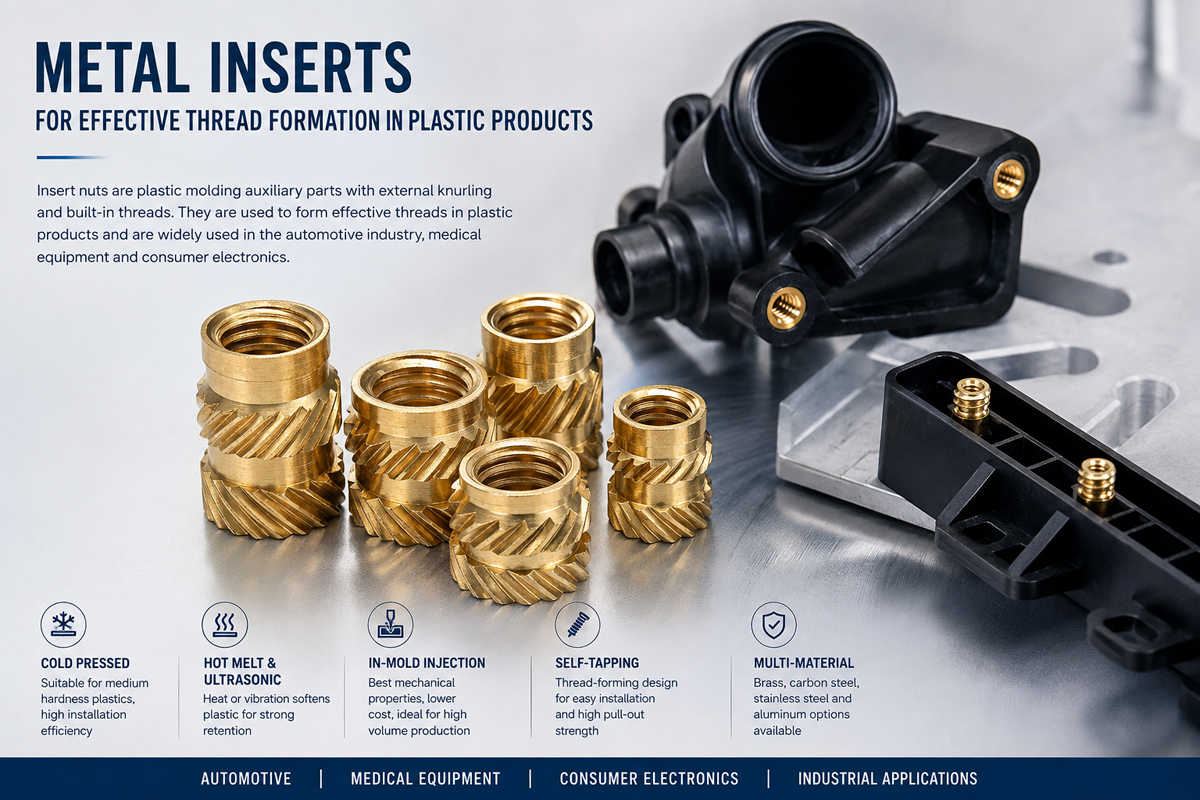
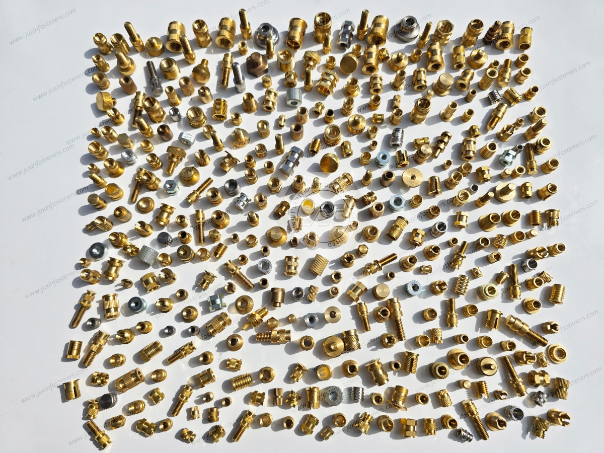
Standard threaded inserts cover many plastic fastening applications.
Custom insert development may be useful where the OEM requires:
Special outside diameter
Restricted boss size
Special length
Custom knurl geometry
Special taper
Flanged geometry
Inch-series thread
Special internal thread
Custom installation feature
Drawing-specific material
Automated assembly compatibility
JUXIN FASTENERS supports standard and drawing-based threaded insert projects for plastic components.
The best results come from reviewing the insert drawing and plastic boss together.
This page is a detailed product page within the threaded-inserts-for-plastic architecture.
Related solutions include:
Heat-Set Threaded Inserts for Plastic Housings & Thermoplastic Assemblies — parent selection guide covering brass and stainless insert technologies
303 Stainless Steel Heat-Set Inserts for Plastic — stainless insert solution for drawing-specified applications
Ultrasonic Threaded Inserts for Plastic — insert selection for ultrasonic installation
Flanged Threaded Inserts for Plastic — inserts with defined seating and bearing surfaces
Threaded Inserts for PA66 and Nylon Components — polymer-specific design considerations
Threaded Inserts for ABS and Polycarbonate Housings — inserts for electronic and equipment enclosures
Fastening Solutions for Medical Device Housings & Laboratory Equipment — enclosure and plastic fastening architecture
Automotive Fastening Solutions — fastening technologies for automotive body, lighting, interior and electronic assemblies
This structure allows the broad threaded-insert guide to answer selection questions while detailed pages capture high-commercial-intent product searches.
If you are designing or sourcing threaded inserts for:
Automotive lighting
Automotive electronics
Electrical equipment
Electronic housings
Communication equipment
Appliances
Medical equipment
Industrial controls
Injection-molded plastic components
Thermoplastic housings
send us your insert drawing, plastic material, boss dimensions, installation method, mating screw, required thread, mechanical requirements and estimated quantity.
If the mold has not yet been finalized, send the plastic boss design as early as possible.
Selecting the insert before the mold is frozen can make it easier to coordinate the insert outside diameter, pilot hole, boss wall thickness and installation process.
JUXIN FASTENERS can evaluate knurled brass inserts, heat-set inserts, ultrasonic inserts, mold-in inserts, flanged inserts,
tapered inserts and drawing-based custom threaded inserts, as well as stainless steel insert configurations for suitable applications.
JUXIN FASTENERS
Website: www.juxinfasteners.com
Engineering & RFQ: info@juxinfasteners.com
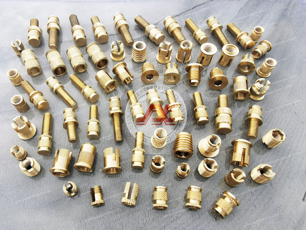
Product Packaging
Packaging Standard
At Juxin Fasteners, we apply standardized export packaging to ensure product protection, traceability, and compliance with international logistics requirements.
1. Standard Export Packaging
Unless otherwise specified, all products will be packed according to our factory standard export packaging, which includes:
Moisture-resistant inner protection
Poly bag or small box packing as required
Reinforced export cartons
Clear labeling with part number, specification, batch number, and quantity
Palletizing for sea or air shipment when necessary
Our standard packaging is designed to ensure safe transportation, efficient warehousing, and long-distance international shipping.
2. Customized Packaging Options
We also provide customized packaging solutions according to customer requirements, including but not limited to:
Private labeling
Customized barcodes
Specific carton dimensions
Retail packaging
Special pallet configuration
Customer-specific marking and identification
So that you know, customized packaging may involve additional costs and extended lead time depending on the complexity of the requirements.
3. Compliance & Quality Assurance
All packaging processes are controlled under our ISO 9001 quality management system to ensure consistency, traceability, and product integrity throughout the supply chain.
Product Pictures
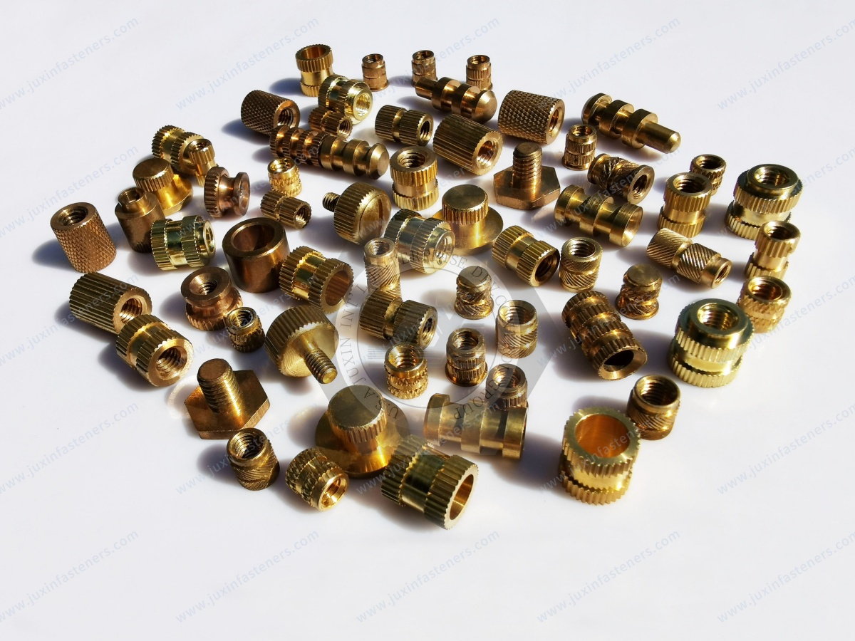
Contact Us
Tel.:
+86 020 8621 0320
+86 020 3121 6067
E-mail:
Technical Support:
Navigation
SEND INQUIREY