Call Us
+86 136 6007 9809
Call Us
+86 136 6007 9809

Automotive manufacturers and Tier 1 suppliers increasingly use engineering thermoplastics in electronic housings, interior assemblies, lighting systems and selected under-hood components.
Materials such as glass-fiber-reinforced polyamide, PBT and polycarbonate can provide useful combinations of weight, manufacturability and functional performance.
Product Specification
Automotive manufacturers and Tier 1 suppliers increasingly use engineering thermoplastics in electronic housings, interior assemblies, lighting systems and selected under-hood components.
Materials such as glass-fiber-reinforced polyamide, PBT and polycarbonate can provide useful combinations of weight, manufacturability and functional performance.
However, replacing a metal component with molded plastic changes the threaded joint.
A screw installed directly into plastic does not behave like a screw installed into a metal nut.
Plastic can experience creep, stress relaxation, temperature-dependent strength changes and damage from repeated assembly.
Metal threaded inserts provide reusable internal threads within compatible plastic components,
but the performance of the joint depends on the insert geometry, polymer, boss design and installation process.
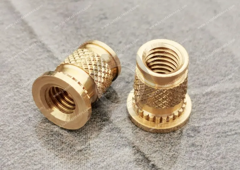
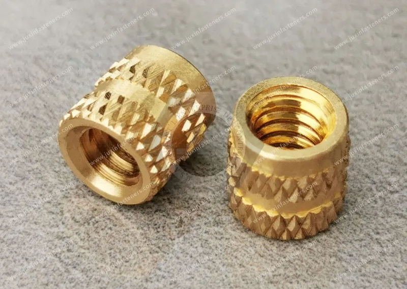
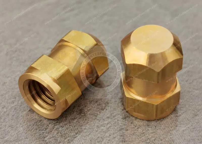
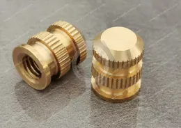
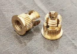
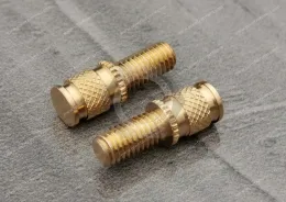
JUXIN FASTENERS supplies threaded insert products, including brass heat-set inserts, knurled inserts and drawing-based insert configurations for industrial plastic assemblies.
This guide focuses on automotive applications, including:
Electronic control unit housings
Automotive lighting assemblies
Interior plastic brackets
Instrument panel components
Sensor housings
Electrical distribution enclosures
Selected under-hood electronic components
Lightweight molded equipment assemblies
The objective is to help design engineers, injection molders and OEM sourcing teams select and qualify suitable threaded insert systems.
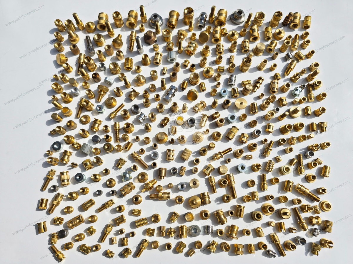
A threaded insert is a separate component installed into or molded within a plastic part to provide a threaded connection.
Common configurations include:
Heat-set threaded inserts
Ultrasonic threaded inserts
Mold-in threaded inserts
Knurled brass inserts
Flanged threaded inserts
Other drawing-specific insert designs
Different installation methods create different mechanical interactions with the polymer.
Therefore, inserts with the same internal thread size are not automatically interchangeable.
Potential advantages include:
Reusable metal internal threads
Reduced wear of the internal thread during repeated assembly
Defined threaded interfaces
Compatibility with selected automated assembly processes
Flexibility in plastic component design
However, threaded inserts do not automatically eliminate plastic creep, boss cracking or joint preload loss.
These problems must be evaluated at the complete assembly level.
ECU housings may require threaded attachment points for covers, brackets and electronic modules.
Important requirements may include:
Dimensional stability
Temperature exposure
Vibration
Assembly torque control
Environmental sealing
The threaded insert must be compatible with the housing material and the actual joint design.
Lighting housings may use engineering thermoplastics for mounting and enclosure functions.
Potential requirements include:
Controlled mounting geometry
Thermal cycling
Vibration
Repeatable assembly
Material compatibility
Potential applications include:
Instrument panel brackets
Console assemblies
Interior equipment housings
Decorative panel attachments
The appropriate fastening method depends on load, service frequency and appearance requirements.
Selected under-hood electronic components may experience elevated temperatures and thermal cycling.
The actual operating temperature must be established for the application.
A threaded insert suitable for an interior component may not be suitable for an under-hood housing.
The performance of a threaded insert depends on at least five elements:
Insert Geometry → Polymer Material → Boss Design → Installation Process → Mating Screw Assembly
A failure in any one element can compromise the joint.
For example:
Correct insert + incorrect boss = possible cracking
Correct insert + incorrect installation = poor retention
Correct insert + incorrect screw torque = possible spin-out
Correct insert + unsuitable polymer = possible creep or relaxation
This is why the insert should be qualified within the actual molded component.
Heat-set inserts are commonly used in suitable thermoplastics.
During installation, heat softens the surrounding polymer and allows the insert to be positioned in the molded hole.
As the polymer cools and solidifies, it engages the insert's external retention features.
Potential applications include:
Electronic housings
Plastic brackets
Lighting components
Instrumentation enclosures
The installation process must be matched to the polymer and insert geometry.
Ultrasonic insertion uses vibration energy to generate localized heating at the insert-plastic interface.
The softened polymer flows around the insert's retention features.
Potential considerations include:
Ultrasonic equipment
Insert geometry
Polymer response
Boss design
Installation depth
Process repeatability
Not every heat-set insert is automatically suitable for ultrasonic installation.
Mold-in inserts are positioned within the mold before plastic injection.
The polymer forms around the insert during molding.
Potential advantages include eliminating a separate post-molding insertion operation.
However, mold-in insertion introduces other requirements, including:
Insert positioning
Mold tooling compatibility
Polymer flow
Insert retention during injection
Dimensional stability
Flash control
Heat-set and ultrasonic inserts require post-molding installation.
Mold-in inserts require integration into the molding process.
The best choice depends on:
Production volume
Tooling
Automation
Cycle time
Insert geometry
Scrap risk
Required performance
A lower insert unit price does not necessarily mean a lower finished assembly cost.
A plastic boss is the molded structure that receives the threaded insert.
Boss cracking may occur when installation creates excessive stress.
Potential causes include:
Undersized pilot hole
Insufficient wall thickness
Aggressive insert geometry
Incorrect installation temperature
Excessive insertion force
Material brittleness
Poor molded-part quality
A cracked boss does not automatically mean the insert material is defective.
The engineer should review:
Boss outside diameter
Hole diameter
Boss height
Insert outside diameter
Insert length
Polymer grade
Installation temperature
Installation force
The correct design should be validated through testing in the actual molded component.
Pull-out resistance describes the axial force required to extract the insert from the plastic under a defined test condition.
It depends on:
Insert geometry
Polymer material
Boss dimensions
Installation process
Test temperature
Loading rate
A pull-out value measured in one polymer should not automatically be applied to another.
Torque-out resistance describes resistance to rotation of the insert within the plastic.
It is particularly important for automated screwdriving.
Potential factors include:
Knurl geometry
Insert diameter
Polymer engagement
Boss design
Installation conditions
Pull-Out: Resistance to axial extraction.
Torque-Out: Resistance to rotation.
A particular knurl design may perform differently in these two tests.
Therefore, an insert should not be selected solely by a claimed pull-out rating.
For screwdriving applications, torque-out resistance may be equally important.
Automotive assembly lines may use automated screwdriving equipment.
Potential concerns include:
Excessive installation torque
Cross-threading
Insert rotation
Screw bottoming
Misalignment
Joint damage
The assembly process should be designed to prevent the applied torque from exceeding the allowable limits of the insert-plastic interface.
A threaded insert may have a measured torque-out value.
However, the assembly torque should not simply be set equal to that value.
The complete joint must consider:
Required clamp load
Screw size
Thread friction
Plastic compression
Insert retention
Safety margin
The correct tightening specification should be established by the OEM.
Threaded inserts may incorporate:
Straight knurls
Diamond knurls
Diagonal knurls
Annular grooves
Other retention features
These features influence how the surrounding polymer engages the insert.
However, no single knurl pattern is universally superior.
A more aggressive external profile may increase mechanical engagement.
But it may also increase local stress or require different installation conditions.
The correct geometry should balance:
Pull-out resistance
Torque-out resistance
Boss integrity
Installation process
Polymer behavior
Automotive components may experience repeated temperature changes.
The actual range depends on the component location.
Thermal cycling may influence:
Polymer stiffness
Insert retention
Joint preload
Differential expansion
Long-term dimensional stability
A metal insert and plastic housing generally have different thermal expansion behavior.
Brass and engineering thermoplastics have different material properties.
The actual thermal expansion of a plastic also depends on:
Polymer type
Reinforcement
Fiber orientation
Temperature
Moisture condition
Therefore, material selection should not be based on the assumption that brass and plastic expand together.
Creep is time-dependent deformation under sustained stress.
Thermoplastics may experience creep depending on:
Temperature
Applied stress
Time
Material grade
Reinforcement
Environmental exposure
Creep can influence the threaded joint.
A brass insert provides a metal internal thread.
However, the insert is still retained by the surrounding plastic.
If the polymer deforms under sustained loading, the joint may experience changes in retention or clamp load.
Therefore, the engineer must evaluate the plastic structure as well as the insert.
Stress relaxation refers to a reduction in stress under sustained deformation.
In plastic assemblies, it can influence:
Clamp load
Boss loading
Joint stability
Long-term service behavior
The correct joint design should consider the material's time- and temperature-dependent properties.
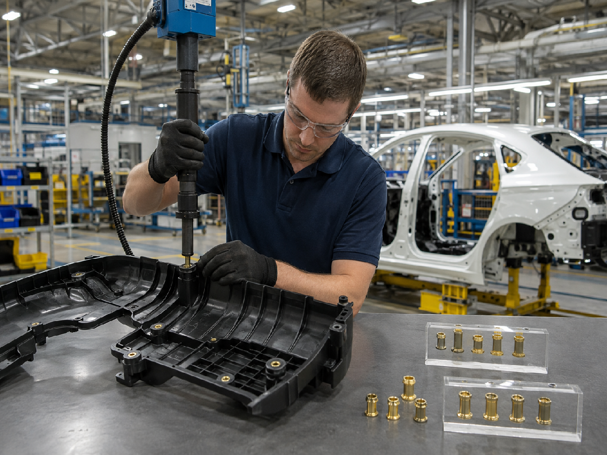
Automotive applications frequently use glass-fiber-reinforced thermoplastics.
Examples include:
PA66-GF30
Other reinforced polyamides
Glass-filled PBT
Reinforcement can change:
Stiffness
Strength
Thermal expansion
Molded-part behavior
Installation response
The actual grade and molding conditions matter.
Different PA66-GF30 grades may have different:
Additives
Moisture behavior
Processing characteristics
Mechanical properties
Thermal performance
Fiber orientation can also influence local properties.
Therefore, insert qualification should use the actual production polymer grade.
Polyamide materials may absorb moisture.
Moisture can influence:
Dimensions
Stiffness
Strength
Long-term behavior
For automotive assemblies, the conditioning state of the plastic may be relevant to testing.
A pull-out test performed on a dry molded sample may produce different results from a test performed after moisture conditioning.
Therefore, OEM test specifications should define relevant environmental and conditioning requirements.
PBT is used in selected automotive electrical and electronic components.
Insert selection should consider:
Polymer grade
Reinforcement
Boss geometry
Installation process
Temperature exposure
The correct insert must be validated in the actual molded component.
Polycarbonate may be used in selected housings and structural plastic components.
Potential considerations include:
Stress cracking
Chemical exposure
Installation stress
Temperature
Boss geometry
The insert design should avoid excessive localized stress.
Environmental stress cracking can occur when susceptible polymers are exposed to particular chemicals while under stress.
Potential sources of stress include:
Insert installation
Molded-in stress
Screw tightening
External loading
The risk depends on the polymer and environment.
A polymer may appear compatible with a chemical under one test condition.
However, the same material may behave differently when mechanically stressed.
For automotive housings exposed to cleaning agents, oils or other fluids, the complete assembly should be evaluated.
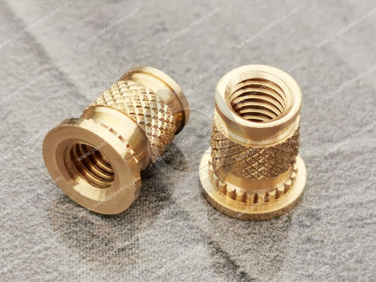
Brass is commonly used for threaded inserts because it offers useful machinability and corrosion behavior for many applications.
Potential material specifications may include suitable grades covered by:
ASTM B16/B16M
EN 12164
However, the exact alloy must be confirmed for the application.
Different brass alloys can contain different alloying elements.
Some free-machining brass grades contain lead.
Automotive customers may impose restrictions or reporting requirements relating to material composition.
Therefore, the RFQ should specify:
Required alloy
Restricted substances
Material reporting requirements
Applicable customer specifications
A generic brass designation is not sufficient for every automotive program.
Stainless steel inserts may be considered for selected applications.
However, stainless steel and brass differ in:
Machinability
Thermal conductivity
Corrosion behavior
Cost
Manufacturing requirements
The correct choice depends on the design.
Stainless steel should not automatically be substituted for brass without reviewing the installation process.
Flanged inserts include an enlarged end feature.
Depending on the design, the flange may influence:
Installation depth
Axial positioning
Bearing contact
Load transfer
However, a flange does not automatically eliminate plastic creep or increase every type of retention strength.
A flanged insert may behave differently depending on the direction of the applied load.
The engineer should consider:
Pull direction
Screw loading
Boss geometry
Flange seating
Installation orientation
The correct geometry depends on the complete joint.
| Selection Factor | Heat-Set Insert | Mold-In Insert |
|---|---|---|
| Installation stage | After molding | During molding |
| Main process | Controlled thermal insertion | Insert placement in mold |
| Tooling | Insertion equipment | Mold integration |
| Automation | Process-dependent | Process-dependent |
| Design concern | Boss geometry and insertion conditions | Insert positioning and molding conditions |
| Qualification | Installed plastic assembly | Molded plastic assembly |
The correct choice depends on the actual manufacturing process.
Direct-thread-forming screws may be suitable for selected plastic assemblies.
Metal threaded inserts may be preferred where reusable internal threads or other specific requirements are important.
| Selection Factor | Metal Threaded Insert | Direct Screw into Plastic |
|---|---|---|
| Internal thread | Metal | Formed or engaged in plastic |
| Additional component | Yes | Usually no insert |
| Assembly process | Insert installation plus screw assembly | Screw assembly |
| Repeated service | Design-dependent | Design-dependent |
| Cost structure | Insert plus installation | Screw and boss design |
| Main concern | Insert retention and plastic behavior | Plastic thread performance |
Neither method is universally superior.
Automotive lightweighting should consider the entire assembly.
A metal insert adds a component and an installation process.
For some low-load, infrequently serviced joints, a suitable direct-threading solution may be more economical.
For other applications, a metal insert may provide useful serviceability and thread durability.
The correct choice depends on functional requirements.
Before finalizing the plastic housing, engineers should review:
Polymer grade
Reinforcement
Boss diameter
Boss height
Pilot hole diameter
Insert geometry
Installation method
Molded-part tolerances
Assembly torque
Service temperature
Environmental exposure
The design should also consider nearby ribs, walls and other molded features.
A late change in insert outside diameter or installation method may require modification to the molded boss.
This can affect:
Mold tooling
Wall thickness
Component packaging
Assembly equipment
Qualification
Therefore, insert selection should be coordinated with plastic component design.
Depending on the application, validation may include:
Pull-out testing
Torque-out testing
Repeated assembly testing
Thermal cycling
Humidity conditioning
Chemical exposure
Vibration testing
Dimensional inspection
The required methods and acceptance criteria should be established by the OEM.
An insert may perform well in a room-temperature pull-out test.
However, elevated temperature can change the properties of the surrounding plastic.
For under-hood applications, the engineer should evaluate performance under relevant environmental conditions.
The exact requirements depend on the vehicle component and location.
A practical qualification process may follow:
Drawing Review → Polymer Review → Boss Geometry Review → Installation Process Review → Sample → Pull-Out / Torque-Out Testing
→ Environmental Validation → Golden Sample Approval → Production
For automated assembly, feeding and installation compatibility should also be evaluated.
Two brass inserts may have:
The same internal thread
Similar length
Similar outside diameter
But differ in:
Knurl geometry
Groove geometry
Installation behavior
Material
Pull-out resistance
Torque-out resistance
Therefore, alternative sourcing should validate the actual molded assembly.
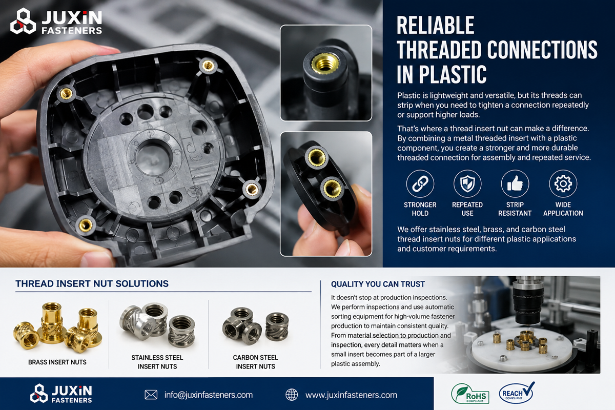
For accurate technical review and quotation, provide:
Insert drawing
Internal thread size
Insert length
Outside diameter
Knurl geometry
Flange geometry where applicable
Material specification
Surface finish
Polymer grade
Reinforcement percentage
Boss drawing
Installation method
Required pull-out resistance
Required torque-out resistance
Operating temperature range
Environmental requirements
Prototype quantity
Annual purchasing forecast
Packaging requirements
Required documentation
For custom inserts, provide a 2D drawing and available 3D model.
A supplier may provide a dimensionally correct insert.
However, the final retention performance depends on installation.
Therefore, qualification should address:
Insert geometry
Plastic boss
Installation equipment
Process parameters
Functional testing
A dimensional certificate alone does not establish complete joint performance.
Depending on the project, inspection may include:
Dimensional verification
Thread inspection
Knurl geometry inspection
Material verification
Surface finish inspection
Functional testing in the specified plastic
Additional documents, including EN 10204 inspection documentation where applicable, should be agreed during RFQ review.
Depending on the actual component and application, relevant references may include:
ISO metric thread specifications
ASME/ANSI inch-thread specifications
ASTM B16/B16M for applicable free-cutting brass rod, bar and shapes
EN 12164 for applicable copper and copper alloy rod for free machining purposes
Relevant ISO or ASTM polymer material and test specifications
EN 10204 for agreed inspection documentation
Customer-specific automotive drawings and validation requirements
There is no single universal ISO or DIN standard defining every heat-set, ultrasonic or mold-in threaded insert.
The applicable product drawing and installation requirements must be confirmed.
Standard threaded inserts cover many applications.
Custom requirements may include:
Special thread sizes
Nonstandard lengths
Custom knurl geometry
Flanged designs
Restricted boss dimensions
Special materials
Customer-specific retention requirements
JUXIN FASTENERS can review drawing-based threaded insert requirements according to manufacturing feasibility.
A broader guide to heat-set insertion, plastic compatibility and threaded insert selection.
Detailed information about knurl geometry, pull-out resistance and torque-out behavior.
Nonmetallic fastening alternatives for selected electronic and plastic assemblies.
Manufacturing process selection for custom fasteners and formed components.
Threaded attachment solutions for automotive metal structures.
These related solutions help engineers compare plastic inserts, direct fastening and metal joining technologies.
Are you sourcing threaded inserts for:
Automotive electronic housings
ECU enclosures
Automotive lighting components
Interior plastic brackets
Instrument panel assemblies
Sensor housings
Power distribution enclosures
Lightweight molded components
JUXIN FASTENERS can review standard and drawing-based threaded insert requirements for industrial and automotive OEM applications.
For efficient technical evaluation, send:
Drawing + Thread Size + Insert Geometry + Polymer Grade + Boss Dimensions + Installation Method + Required Retention + Quantity
If your project includes elevated temperature, thermal cycling or automotive material restrictions, please include the relevant specifications.
The objective is to select an insert that performs reliably in the actual molded component—not merely one that matches the nominal thread size.
JUXIN FASTENERS
Website: www.juxinfasteners.com
Engineering & RFQ: info@juxinfasteners.com
Send your drawing and application requirements for technical review and quotation.
Product Packaging
Packaging Standard
At Juxin Fasteners, we apply standardized export packaging to ensure product protection, traceability, and compliance with international logistics requirements.
1. Standard Export Packaging
Unless otherwise specified, all products will be packed according to our factory standard export packaging, which includes:
Moisture-resistant inner protection
Poly bag or small box packing as required
Reinforced export cartons
Clear labeling with part number, specification, batch number, and quantity
Palletizing for sea or air shipment when necessary
Our standard packaging is designed to ensure safe transportation, efficient warehousing, and long-distance international shipping.
2. Customized Packaging Options
We also provide customized packaging solutions according to customer requirements, including but not limited to:
Private labeling
Customized barcodes
Specific carton dimensions
Retail packaging
Special pallet configuration
Customer-specific marking and identification
So that you know, customized packaging may involve additional costs and extended lead time depending on the complexity of the requirements.
3. Compliance & Quality Assurance
All packaging processes are controlled under our ISO 9001 quality management system to ensure consistency, traceability, and product integrity throughout the supply chain.
Product Pictures
Hot Products
Contact Us
Tel.:
+86 020 8621 0320
+86 020 3121 6067
E-mail:
Technical Support:
Navigation
SEND INQUIREY