Call Us
+86 136 6007 9809
Call Us
+86 136 6007 9809

Modern sheet-metal enclosures, electrical cabinets, HVAC equipment, industrial machinery and fabricated chassis frequently use folded panel edges to increase local stiffness,
create mounting surfaces, control enclosure geometry or provide interfaces for covers and service panels.
Product Specification
Modern sheet-metal enclosures, electrical cabinets, HVAC equipment, industrial machinery and fabricated chassis frequently use folded panel edges to increase local stiffness,
create mounting surfaces, control enclosure geometry or provide interfaces for covers and service panels.
These formed edges also create a specific fastening challenge.
A threaded attachment point located near a flange, return or folded edge must fit within a three-dimensional geometry that can include the sheet thickness,
bend radius, flange width, hole setback, nearby return features and restricted installation clearance.
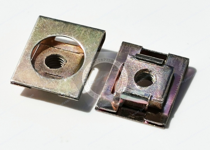
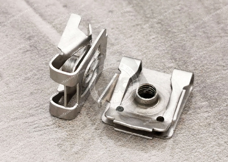
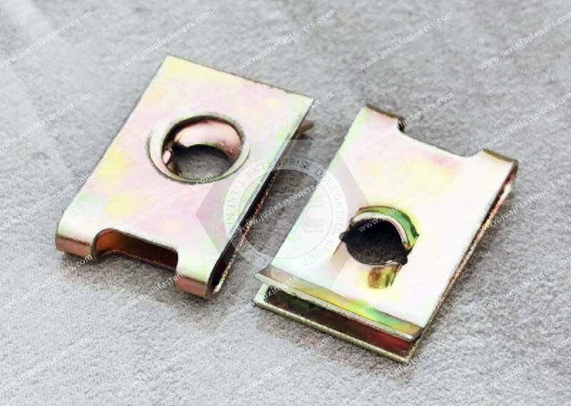
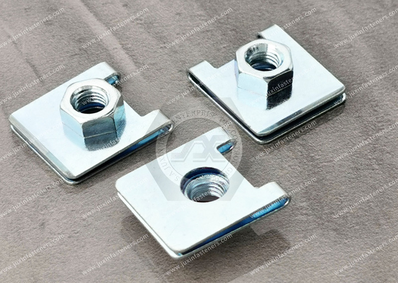
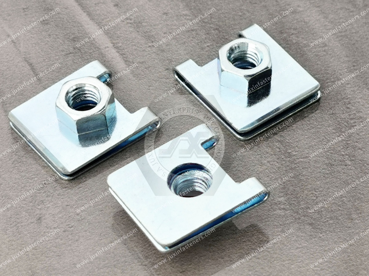
Clip-on nuts for flanged edges provide an edge-installed fastening option for suitable folded sheet-metal assemblies where a removable screw connection is required without adding a loose nut behind the panel.
Unlike a fastening point located in the middle of a flat sheet, however, a flanged-edge application cannot be specified correctly from thread size alone.
The more useful engineering question is:
Can the selected clip-on nut physically fit the actual flange cross-section, align with the mounting hole,
accommodate the panel thickness and coating condition, and remain accessible throughout the production assembly sequence?
For OEM applications, JUXIN FASTENERS recommends evaluating the actual formed-panel drawing together with the required fastener geometry rather than treating all folded sheet-metal edges as equivalent.
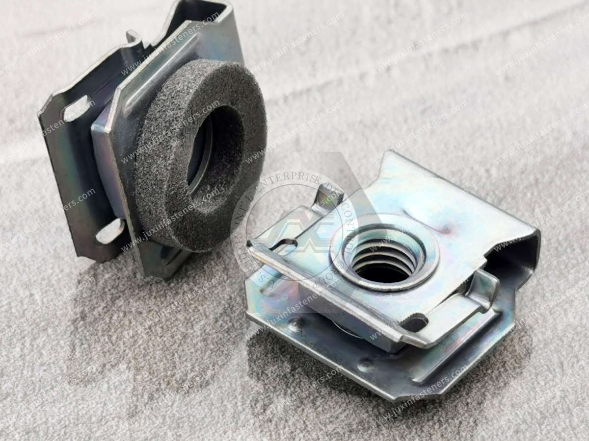
A clip-on nut for a flanged edge is an edge-mounted spring fastener designed to position a threaded or screw-engaging feature on a formed sheet-metal structure.
Depending on the product geometry and application, the fastener may engage:
a straight sheet edge;
a bent flange;
a returned edge;
a folded section;
a multi-layer edge condition;
another formed sheet-metal profile.
The clip is generally installed from an accessible edge and positions the fastening feature relative to a mating hole or screw path.
This can create a removable threaded attachment without requiring a loose nut to be manually held behind the panel during final assembly.
However, commercial terminology varies.
“Flanged-edge clip nut,” “edge clip nut,” “spring nut,” “U-nut” and related terms should not be assumed to describe dimensionally identical products.
The actual cross-sectional geometry should control the selection.
One of the most important distinctions in flanged-edge fastening is that a flange, return and hem should not automatically be treated as the same panel condition.
A single flange is created when the sheet is bent away from the primary panel surface.
The resulting fastening condition depends on:
sheet thickness;
flange width;
bend angle;
inside bend radius;
hole position;
surrounding clearance.
A returned edge introduces another formed section beyond the initial bend.
This can change the available space for the clip body and may interfere with the lower or upper leg of a conventional clip-on nut.
A hem folds material back toward the original sheet, potentially creating a multi-layer edge condition.
The effective interface seen by the clip can therefore be very different from a single sheet of the same nominal material thickness.
The exact hem geometry matters.
An open hem, partially closed hem or tightly formed hem should not automatically be assumed to create the same gripping condition.
This leads to an important engineering rule:
Specify the flange cross-section, not merely the base sheet gauge.
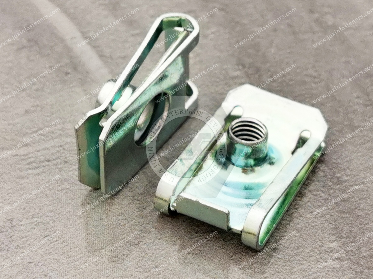
A flanged-edge clip nut must perform several geometric functions before the mating screw is even tightened.
The clip must:
enter from the available edge;
pass around the relevant panel geometry;
seat in the intended position;
align its threaded or screw-engaging feature with the mating hole;
avoid interference with the bend or return;
remain appropriately positioned for screw installation.
These are primarily fit and positioning requirements.
They should not be confused with the final mechanical strength of the completed joint.
Forming a sheet into a flange changes the local geometry and stiffness of the panel.
However, this does not mean every flanged-edge clip nut automatically becomes more stable than the same fastener on a flat edge.
The actual behavior depends on how the fastener interfaces with:
the flange;
the bend;
the return;
the sheet thickness;
the available seating surfaces.
Some clip geometries may be designed specifically for particular formed edges.
Others may require sufficient distance from the bend so that the clip can seat on a relatively flat section.
The component drawing should therefore be reviewed before assuming that the clip legs conform directly to the bend radius.
For an edge-mounted clip nut, hole setback describes the relationship between the accessible edge and the required screw or threaded location.
This dimension is especially important on narrow flanges.
If the fastening point is positioned incorrectly relative to the clip reach, the threaded feature may not align with the panel hole.
Potential assembly symptoms can include:
difficult screw starting;
thread misalignment;
clip displacement;
incomplete seating;
interference with the bend;
production rework.
The required hole setback should therefore be compared with the actual throat or reach dimension of the selected clip-on nut.
A flange can be wide enough to contain a mounting hole but still be unsuitable for a particular clip.
Why?
Because the fastener requires space not only for the hole but also for its own body.
The engineer must consider:
Edge → Clip Entry → Clip Throat → Hole Center → Bend / Adjacent Geometry
This sequence creates a geometric stack-up.
If the flange is too narrow for the selected clip architecture, the fastener may contact the bend before the thread reaches the hole.
Conversely, a different clip geometry may fit the same flange.
This is why flange width, hole setback and throat depth should be evaluated as one system.
A sheet-metal drawing may show a flange angle and nominal dimensions but still omit a fastening issue visible only in cross-section.
The bend radius occupies physical space.
If a clip is positioned too close to the bend, its body or spring leg may contact the curved transition rather than seating against the intended surface.
This can affect:
installed position;
thread alignment;
clip orientation;
local contact;
assembly consistency.
For tight packaging conditions, the RFQ should include the relevant bend radius or a complete cross-sectional drawing.
Real fabricated enclosures rarely consist of infinitely long, isolated flanges.
At corners, sheet-metal fabricators may use:
bend reliefs;
corner notches;
seams;
overlapping panels;
welded corners;
formed transitions.
A clip-on nut located near one of these features may experience a very different installation envelope from the same fastener located in the middle of a straight flange.
Design engineers should therefore evaluate the local flange geometry at the actual fastening point, not only the nominal flange dimension elsewhere on the panel.
Gemini's original concept correctly identifies thickness as important, but “sheet gauge” alone may not describe the interface.
A clip installed over a single flange may engage approximately one sheet layer.
A clip installed over a hemmed or overlapping condition may encounter multiple layers or a more complex formed stack.
The relevant dimension is therefore the actual thickness or cross-sectional condition presented to the clip.
For an OEM RFQ, useful information includes:
base sheet thickness;
thickness tolerance;
number of layers at the clip location;
gap between layers where applicable;
coating thickness where relevant;
final formed cross-section.
A clip selected from base material thickness alone may not fit the finished flange.
One reason engineers consider flanged-edge clip nuts is the ability to create an edge-mounted fastening point without adding a welding operation at that location.
This can be useful when:
the production sequence does not favor welding;
the assembly requires removable hardware;
edge installation is available;
welding would add unnecessary processing;
the component has already passed through earlier fabrication operations.
However, clip-on nuts and weld nuts are not equivalent fastening technologies.
Weld nuts may be preferable where a permanently welded threaded point is required and the material, joint design and production process support welding.
Clip-on nuts may be preferable where edge accessibility, serviceability and mechanical installation better fit the manufacturing architecture.
Installing a clip-on nut does not require welding heat at the fastening location.
This avoids introducing a new thermal joining operation during clip installation.
That can be useful on formed panels where additional welding would complicate the production sequence.
However, it should not be claimed that every weld nut application automatically causes unacceptable thermal warpage.
Welding effects depend on:
sheet material;
sheet thickness;
weld process;
heat input;
weld location;
fixture design;
component geometry;
production controls.
The correct comparison is therefore manufacturing-process specific.
Electrical cabinets, HVAC housings and industrial enclosures are frequently painted or powder coated.
Clip-on nuts may sometimes be installed after finishing, but the coating changes the final panel interface.
The engineer should consider:
coating thickness;
coating hardness;
edge buildup;
risk of coating damage during clip installation;
dimensional change relative to the bare sheet;
corrosion requirements at contact points;
cosmetic requirements.
A clip selected on an uncoated prototype may fit differently on the finished production panel.
This creates another important sourcing principle:
The production panel condition should be specified—not only the bare-metal thickness.
Installing a clip-on nut after a coating process can avoid exposing the fastener's internal thread to the same coating operation used on the panel.
This may simplify certain finishing sequences.
However, whether post-coating installation is appropriate depends on the product, coating, assembly process and cosmetic requirements.
The clip itself can contact the finished surface during installation.
Therefore, coating damage and installation marks should be evaluated where appearance or corrosion protection is critical.
This distinction remains essential for flanged-edge fasteners.
Clip retention concerns how the clip remains positioned on the flange before and during screw installation.
Joint strength concerns the performance of the completed fastener, screw and panel assembly.
Final joint behavior depends on factors including:
screw specification;
thread engagement;
clip or nut geometry;
panel material;
panel thickness;
flange geometry;
local stiffness;
bearing area;
tightening process;
clamp load;
tensile loading;
shear loading;
vibration or cyclic loading;
environmental exposure.
A clip that remains firmly positioned during handling should not automatically be described as a high-strength structural joint.
Likewise, the term Strong-Grip should not be interpreted as a universal pull-off, vibration, fatigue or structural rating without product-specific validation.
A formed flange can change the stiffness and load path of a sheet-metal component.
But it is not technically correct to claim that installing a clip nut on a flange automatically distributes clamp load across the fold or prevents panel crushing.
The completed load path depends on:
screw location;
joint stack;
flange width;
panel thickness;
material;
bearing surfaces;
fastener geometry;
tightening condition.
If local panel deformation is a design concern, it should be evaluated from the complete assembly.
Carbon steel and spring steel may be used for clip-on fastener designs depending on the specific product.
Material selection should consider:
required clip geometry;
forming requirements;
panel fit;
environmental exposure;
surface treatment;
mating materials;
customer specification.
Material names alone should not be used to infer:
hardness;
heat treatment;
fatigue resistance;
vibration resistance;
pull-off strength;
torque capacity.
If a specific material grade is required, it should be defined in the customer drawing or RFQ.
For applications involving humidity, cleaning exposure or other corrosion considerations, stainless steel may be relevant where the required product geometry is available.
JUXIN FASTENERS product information includes stainless clip-on nut options, including SUS304 and SUS316 in relevant product families.
However, this should not be interpreted as confirmation that every flanged-edge clip nut geometry is available in both grades.
Material and dimensional availability should be confirmed for the actual RFQ.
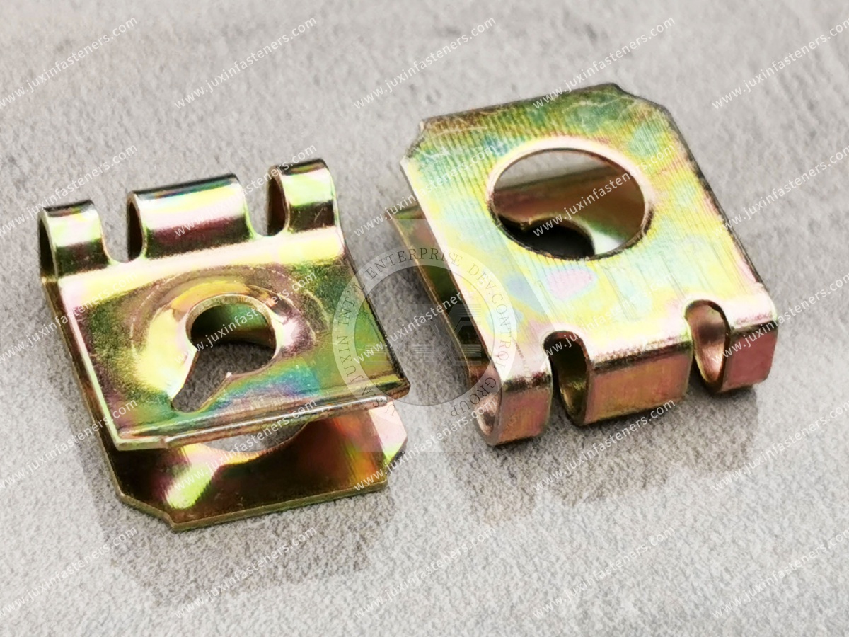
Carbon-steel clip-on nuts may use zinc-based coatings, phosphate-based finishes or other project-specific surface treatments.
The required finish should be selected according to:
service environment;
humidity;
condensation;
chemical exposure;
mating materials;
appearance;
customer specification.
A generic coating should not be presented as evidence of a specific corrosion life.
Where salt-spray testing or another corrosion test is required, the customer should define the test method and acceptance criteria.
Global OEM equipment can use metric or inch fastening systems.
For either system, the thread is only one part of the selection.
The engineer should define:
thread designation;
pitch where applicable;
mating screw;
screw length;
panel thickness;
flange thickness or stack;
hole diameter;
hole setback;
throat depth;
flange width;
bend geometry;
material;
finish.
Specific metric and inch availability should be confirmed against the required JUXIN FASTENERS geometry.
The exact procedure depends on product geometry, but the engineering sequence generally begins before the fastener reaches the assembly line.
Verify the actual formed condition, including thickness, flange width, bend radius and any return or hem.
Check that the selected clip's fastening feature can align with the panel hole.
Ensure that the fastener can physically slide onto the edge from the required direction.
Review bends, corners, brackets, seams and adjacent components.
The fastener should seat according to its design rather than being forced over an incompatible panel condition.
The mating screw should approach the threaded or screw-engaging feature without requiring excessive lateral displacement of the clip.
Where the application has defined mechanical or environmental requirements, test the completed assembly under representative conditions.
A fastener may fit the finished CAD model but still be impossible to install during production.
For example:
A flange may be accessible immediately after bending.
Later, another panel may close the edge.
If the clip is intended to be installed after that second operation, there may no longer be enough access.
Manufacturing engineers should therefore ask:
At what production stage is the clip installed?
Is the panel edge still accessible?
Has coating already been applied?
Are adjacent components already installed?
Can an operator or automated system approach the edge?
Can the clip be replaced later if service is required?
This is a major reason to include manufacturing engineering in fastener selection before design release.
Electrical cabinets frequently use folded sheet-metal frames, doors, internal brackets and removable service panels.
These structures can be strong candidates for flanged-edge clip nuts when the actual geometry supports edge installation.
Potential applications include:
cabinet frames;
folded door structures;
removable covers;
internal brackets;
access panels;
control enclosure components;
selected barrier-panel attachments.
Important selection variables include:
flange width;
hole setback;
coating condition;
panel thickness;
edge accessibility;
internal component clearance;
screw length;
service requirements.
Clip-on nuts should not automatically be treated as grounding or electrical bonding components unless that function has been separately engineered and validated.
HVAC equipment often contains folded sheet-metal housings, blower covers, service doors, control enclosures and flanged structures.
Clip-on nuts can be considered for suitable removable fastening points on these assemblies.
Potential applications include:
air-handling unit covers;
blower housings;
equipment access panels;
control boxes;
service panels;
folded housing flanges.
The engineering focus should remain on:
panel geometry;
flange thickness;
hole position;
service access;
screw compatibility;
corrosion environment.
A clip-on nut itself does not create an airtight joint.
Air leakage performance depends on the complete assembly, including panel design, gasket or seal where used, joint spacing, clamp distribution and other enclosure details.
Industrial machinery uses fabricated sheet-metal covers, guards, access doors and control housings.
Flanged-edge clip nuts may be useful where:
removable panels are required;
a loose backside nut is inconvenient;
the edge remains accessible;
welding is not preferred at the fastening location.
Potential applications include:
equipment covers;
control housings;
maintenance panels;
selected machine guards;
internal brackets.
Safety-related guards and load-sensitive joints require application-specific engineering validation. A generic clip-on nut should not be assumed suitable for a safety-critical connection.
Suitable automotive applications may include non-structural sheet-metal brackets, service covers, interior mounting structures and other edge-accessible components.
Automotive engineers should consider:
panel tolerance;
coating;
installation sequence;
serviceability;
packaging clearance;
vibration and cyclic environment where relevant.
Automotive use should not be interpreted as automatic vibration, fatigue, crash or structural qualification.
Those requirements must be validated for the specific joint.

Compact robotic and automation equipment can use folded sheet-metal control housings, controller cabinets, sensor enclosures and removable covers.
For these assemblies, flange-mounted clip nuts may provide a useful captive fastening point where:
internal clearance is limited;
the panel edge is accessible;
service panels must be removable;
loose nuts would complicate assembly.
The engineer should compare the installed clip envelope with nearby electronics, cables and moving equipment.
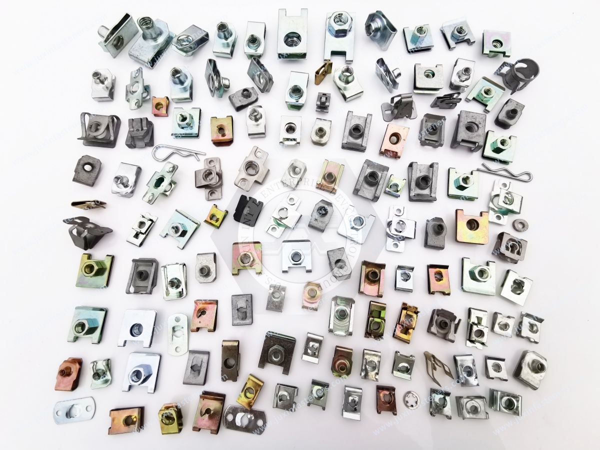
A conventional U-nut or J-nut may work on some flanged structures.
A dedicated flanged-edge geometry may be more appropriate for others.
The correct choice depends on:
flange cross-section;
panel thickness;
hole setback;
available throat depth;
installation access;
bend interference.
For a broader geometry comparison, engineers can refer to the JUXIN FASTENERS guide U-Nuts vs J-Nuts: Geometric Selection for Edge-Mounted Sheet Metal at /solutions/u-nuts-vs-j-nuts-geometry.
The product names alone should not determine the final selection.
An enclosed hex clip nut may be considered when the design specifically benefits from a captive hex-nut-style threaded element.
A flanged-edge clip nut is selected primarily around the formed edge geometry.
These categories can overlap depending on actual product design, but they answer different engineering questions.
JUXIN FASTENERS provides further guidance on Strong-Grip Clip-On Enclosed Hex Nuts for Captive Panel Fastening at /solutions/strong-grip-clip-on-enclosed-hex-nuts.
Some clip-on nuts are designed for use with tapping screws rather than a conventional machine-threaded nut interface.
The correct architecture depends on:
mating screw;
service requirements;
panel geometry;
assembly method;
fastening location.
For more information, see the JUXIN FASTENERS guide on Strong-Grip Clip-On Nuts for Tapping Screws at /solutions/strong-grip-clip-on-nuts-tapping-screws.
These products should not be treated as automatically interchangeable.
Weld nuts create a permanently welded threaded attachment.
Clip-on nuts provide a mechanically installed edge-mounted alternative.
Engineers may compare them based on:
panel material;
welding availability;
production sequence;
coating sequence;
edge accessibility;
serviceability;
load requirements;
production volume.
A clip-on nut avoids welding at its own installation stage, but this does not make it universally superior to a weld nut.
Self-clinching nuts can create permanent captive threads in suitable sheet material using mechanical installation.
They may be more appropriate when the fastening point is not accessible from an edge.
Flanged-edge clip nuts may be attractive when the edge is accessible and clip-on installation fits the production process.
The technologies solve different manufacturing problems.
Blind rivet nuts are installed through prepared holes and can create threaded attachment where installation is available primarily from one side.
Flanged-edge clip nuts require access to the panel edge.
A useful access decision is therefore:
Edge accessible → consider an edge-mounted clip architecture.
Edge inaccessible but prepared hole accessible from one side → evaluate a blind rivet nut architecture.
Other mechanical, environmental and production requirements must then be considered.
One of the strongest Information Gain opportunities in this topic is reversing the usual selection process.
Instead of designing the entire flange first and asking procurement to find a clip that fits afterward, engineering can evaluate the fastening interface while the flange geometry is still adjustable.
The design team can coordinate:
Flange Width → Bend Radius → Hole Setback → Clip Reach → Panel Thickness → Screw Path → Installation Direction
This can reduce the risk of discovering late in the project that the specified fastener cannot physically seat on the finished panel.
A visually similar flanged-edge clip nut is not automatically interchangeable.
Procurement and supplier-development teams should compare:
overall clip geometry;
panel fit;
flange fit;
throat/reach dimension;
hole setback;
thread or screw interface;
installation direction;
material;
finish;
coating compatibility;
surrounding clearance;
drawing revision;
packaging requirements;
inspection requirements.
Thread size alone is not enough to approve an alternative.
For prototype evaluation, supplier development or production sourcing, provide JUXIN FASTENERS with the actual formed-panel information wherever possible.
A useful RFQ package should include:
2D drawing;
flange cross-section;
3D CAD model if available;
reference photo or existing sample;
customer part number;
required clip-on nut geometry if already defined;
metric or inch requirement;
thread size;
thread pitch where applicable;
mating screw specification;
screw length;
base sheet material;
nominal sheet thickness;
sheet thickness tolerance;
number of layers at the clip location;
flange width;
flange angle;
bend radius where critical;
return or hem geometry;
hole diameter;
hole setback;
critical clearance dimensions;
coating or paint condition;
material requirement;
surface treatment requirement;
corrosion/environmental requirements;
installation direction;
assembly method;
prototype/sample quantity;
estimated production quantity;
annual demand;
packaging requirements;
inspection requirements;
customer-specific specifications.
A reliable sourcing path for flanged-edge clip nuts is:
Sheet-Metal Cross-Section → Flange Geometry → Panel/Stack Thickness → Bend Clearance → Hole Setback → Clip Reach →
Screw Interface → Installation Sequence → Prototype Fit Evaluation → Joint Validation → Production Specification → RFQ
This approach connects sheet-metal design directly with fastener sourcing.
For custom or drawing-based Clip-On Nuts for Flanged Edges, U-nuts, J-nuts, spring nuts and related sheet-metal fastening requirements, contact JUXIN FASTENERS at info@juxinfasteners.com.
Providing the actual flange cross-section, panel thickness,
hole position and mating screw information allows JUXIN FASTENERS to evaluate the fastening requirement more effectively than specifying a thread size or sheet gauge alone.
Product Packaging
Packaging Standard
At Juxin Fasteners, we apply standardized export packaging to ensure product protection, traceability, and compliance with international logistics requirements.
1. Standard Export Packaging
Unless otherwise specified, all products will be packed according to our factory standard export packaging, which includes:
Moisture-resistant inner protection
Poly bag or small box packing as required
Reinforced export cartons
Clear labeling with part number, specification, batch number, and quantity
Palletizing for sea or air shipment when necessary
Our standard packaging is designed to ensure safe transportation, efficient warehousing, and long-distance international shipping.
2. Customized Packaging Options
We also provide customized packaging solutions according to customer requirements, including but not limited to:
Private labeling
Customized barcodes
Specific carton dimensions
Retail packaging
Special pallet configuration
Customer-specific marking and identification
So that you know, customized packaging may involve additional costs and extended lead time depending on the complexity of the requirements.
3. Compliance & Quality Assurance
All packaging processes are controlled under our ISO 9001 quality management system to ensure consistency, traceability, and product integrity throughout the supply chain.
Product Pictures
Contact Us
Tel.:
+86 020 8621 0320
+86 020 3121 6067
E-mail:
Technical Support:
Navigation
SEND INQUIREY