Call Us
+86 136 6007 9809
Call Us
+86 136 6007 9809

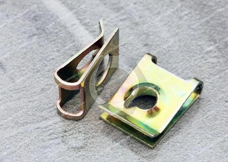
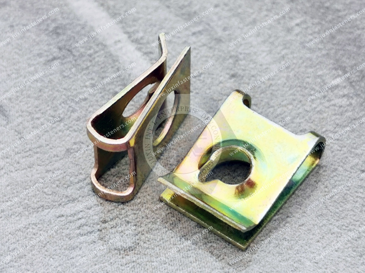
Clip-on nuts and U-nuts are spring-type fastening components designed to provide a captive or temporarily retained threaded fastening point on suitable panel edges and flanges.
They are commonly considered for automotive trim, vehicle body panels, HVAC equipment, electrical enclosures, machinery covers, and fabricated sheet metal assemblies.
Product Specification
Clip-on nuts and U-nuts are spring-type fastening components designed to provide a captive or temporarily retained threaded fastening point on suitable panel edges and flanges.
They are commonly considered for automotive trim, vehicle body panels, HVAC equipment, electrical enclosures, machinery covers, and fabricated sheet metal assemblies.
In these applications, engineers frequently need to attach two components where access to the reverse side of the supporting panel is limited.
A conventional loose nut may require an additional operator, assembly tool, or access opening.
Welding a nut may introduce additional manufacturing operations and may be unsuitable for certain finished or coated components.
A properly selected clip-on nut can simplify the assembly by positioning the fastening feature at the panel edge before the mating screw is installed.
However, the performance of a clip-on nut depends on several interacting factors:
Panel thickness and material.
Panel edge geometry.
Hole-to-edge distance.
Clip throat depth.
Spring retention characteristics.
Thread or screw-engagement design.
Surface treatment.
Assembly loading.
Installation and removal requirements.
JUXIN FASTENERS supports industrial B2B sourcing inquiries for spring steel fastening components and drawing-based OEM fastening requirements.
This engineering guide explains how to select clip-on nuts and U-nuts for automotive and industrial sheet metal assemblies, evaluate their mechanical limitations,
improve assembly-line consistency, and prepare technical specifications for OEM procurement.
A clip-on nut is a fastening component that attaches to a panel edge, flange, or other compatible feature and provides a means of engaging a mating screw.
Many designs use spring steel arms that grip the supporting panel.
The clip may be installed before the mating screw, allowing the assembly operator to position the fastening feature without holding a loose nut behind the panel.
A conventional U-shaped clip nut has two arms connected by a curved section.
The clip slides over a suitable panel edge.
One or both arms may incorporate features that position the clip and engage the mating screw.
Depending on the design, the fastening feature may be:
A formed thread.
An extruded threaded feature.
A captive threaded element.
A screw-engagement feature intended for a specified screw type.
The exact construction must be identified before selecting a mating fastener.
Potential advantages include:
Installation from an accessible panel edge.
Reduced handling of loose nuts.
Positioning of the fastening feature before final assembly.
Simplified maintenance access.
Potential reduction in assembly operations.
Compatibility with suitable coated or prefinished panels.
Removable fastening arrangements.
These benefits depend on the product design and the actual assembly process.
A clip-on nut is not automatically a structural fastening solution.
Its suitability depends on the screw, clip geometry, supporting panel, applied loads, and complete joint design.
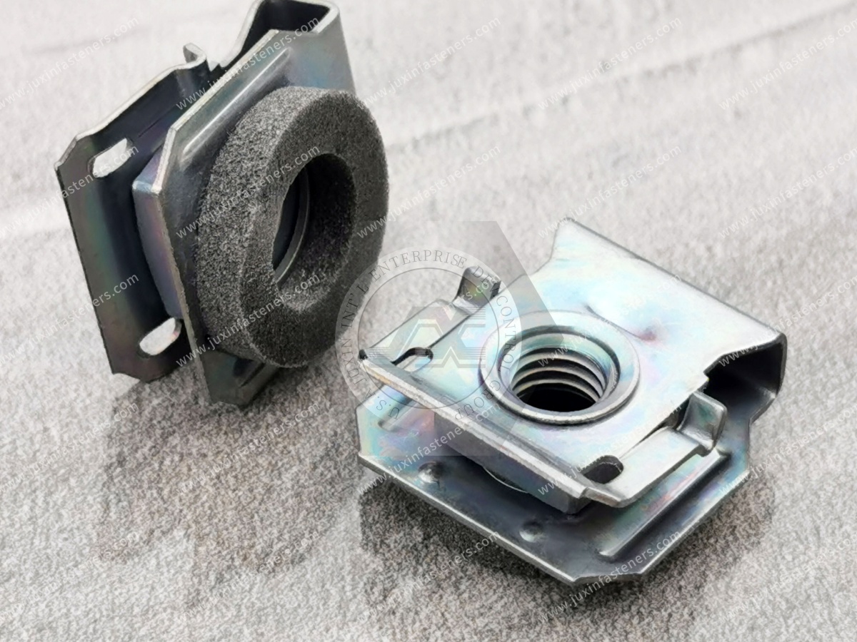
Industrial buyers frequently encounter overlapping terminology when searching for panel fastening components.
However, similar commercial names do not guarantee interchangeable designs.
U-nuts generally feature a U-shaped spring clip that fits over a panel edge.
They are commonly used where a fastening hole is located a defined distance from the edge.
J-nuts typically use an asymmetrical clip configuration.
The geometry may be appropriate for particular edge access or installation conditions.
The exact distinction between commercial U-nut and J-nut product families can vary by supplier.
Speed nut is a broad commercial term often associated with spring steel fastening devices.
Certain speed nuts engage specially designed screws or studs rather than providing a conventional machine-screw thread.
They should not automatically be substituted for threaded U-nuts.
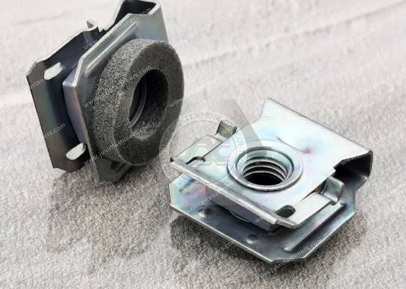
The term chimney nut is often used for clip nuts with a raised or extruded screw-engagement feature.
The raised geometry may provide additional thread engagement or a specific screw interface, depending on the design.
A chimney-style feature does not establish a universal thread strength or load rating.
| Fastener Type | Typical Configuration | Key Selection Consideration |
|---|---|---|
| U-nut | U-shaped panel-edge clip | Panel thickness, throat depth and hole alignment |
| J-nut | Asymmetrical edge clip | Edge geometry and installation access |
| Speed nut | Spring-type screw-retaining fastener | Compatible screw type and engagement method |
| Chimney-style clip nut | Clip with raised screw-engagement feature | Thread geometry and available engagement |
| Conventional loose nut | Separate threaded component | Backside access and assembly handling |
| Weld nut | Nut permanently joined by welding | Weldability, process control and surface finish |
The purchasing specification should identify the actual part geometry and mating screw requirements rather than relying only on a commercial name.
Many clip-on nuts are produced from spring steel strip.
Spring steel provides the elastic behavior required for a clip to grip a compatible panel edge.
During installation, the clip arms deflect as the component slides over the panel.
After installation, the clip should provide sufficient retention to remain in position under the specified handling and assembly conditions.
The design must avoid excessive permanent deformation.
Important properties may include:
Yield strength.
Elastic behavior.
Hardness.
Fatigue performance.
Formability.
Surface condition.
Corrosion resistance.
Depending on the steel grade and manufacturing process, heat treatment may be used to achieve the required mechanical properties.
However, not every clip nut uses the same material grade or heat-treatment process.
The approved drawing and material specification should define the relevant requirements.
Stainless steel spring-type components may be considered for certain environments.
However, stainless steel is not automatically equivalent to a carbon spring steel design.
Elastic properties, forming behavior, strength, corrosion exposure, and component geometry must be evaluated.
For nonstandard applications, a drawing-based spring steel component may require evaluation of:
Strip thickness.
Bend radii.
Forming sequence.
Material condition.
Spring deflection.
Surface treatment.
Thread formation.
Dimensional tolerances.
Manufacturing feasibility must be confirmed against the submitted design.
Panel thickness is one of the most important dimensions when selecting a U-nut.
The spring clip must accommodate the actual panel thickness without excessive deformation or inadequate retention.
A panel thicker than the specified range may cause:
Excessive clip-arm deflection.
Permanent deformation.
Difficult installation.
Damage to the coating.
Incomplete seating.
Reduced serviceability.
A panel thinner than the intended range may result in:
Loose clip retention.
Movement during handling.
Misalignment.
Increased risk of clip displacement.
Inconsistent assembly positioning.
Sheet metal thickness is subject to manufacturing tolerances.
For example, a nominally specified sheet may have an acceptable range of actual thicknesses.
The clip should be selected for the complete permitted thickness range.
Paint, powder coating, plating, or other surface treatments can change the effective thickness at the installation location.
This is particularly important when a clip is installed after coating.
A formed flange may have local geometry that differs from the flat sheet thickness.
Bend radii, edge conditions, and local deformation can affect clip installation.
A broad range such as 0.5–4.0 mm may describe the general market for certain clip designs, but it is not a universal specification for every U-nut.
The actual allowable range must be confirmed for the selected component.
The relationship between the mounting hole and panel edge determines whether the clip's screw-engagement feature aligns correctly.
Throat depth generally describes the distance from the clip's edge-engagement region to its fastening feature or another defined reference point.
The exact measurement convention depends on the product drawing.
The panel drawing should define the distance from the relevant panel edge to the center of the screw hole.
The clip geometry must position its threaded or screw-engagement feature at the required location.
Incorrect geometry may cause:
Cross-threading.
Difficult screw insertion.
Clip movement.
Uneven loading.
Assembly delays.
Damage to the panel or clip.
The clip must also accommodate the actual edge geometry.
Important features include:
Straight or curved edges.
Flange width.
Bend radius.
Nearby embossments.
Reinforcement features.
Edge burrs.
Local coating thickness.
For a new OEM application, engineers should evaluate the clip together with the panel drawing and mating screw rather than treating these as independent components.
Clip-on nut performance involves two distinct characteristics: insertion force and retention force.
Insertion force is the force required to install the clip onto the panel.
It depends on:
Spring geometry.
Panel thickness.
Material condition.
Coating.
Edge shape.
Installation direction.
Friction.
Retention force describes the resistance of the installed clip to removal or displacement under a defined test condition.
The required retention depends on the manufacturing and service application.
A clip with excessive insertion force may be difficult to install.
A clip with insufficient retention may move or detach before the mating screw is assembled.
The correct design balances these requirements.
Increasing spring interference may improve certain retention characteristics but can also:
Increase insertion force.
Damage panel coatings.
Cause permanent spring deformation.
Reduce installation ergonomics.
Complicate maintenance removal.
Insertion and retention should be evaluated using defined test methods and representative panel samples.
Results obtained on one sheet material or thickness should not automatically be applied to another.
A critical distinction is the difference between clip retention on the panel and the locking performance of the completed screw joint.
The spring arms help keep the clip in position.
This is especially useful before the mating screw is installed.
The completed joint depends on the screw, threaded engagement, clamp load, panel stiffness, and applied service loads.
A clip that remains firmly attached to the panel does not necessarily prevent the mating screw from loosening under vibration.
Joint loosening may be influenced by:
Insufficient preload.
Transverse joint movement.
Settlement.
Embedment.
Thermal cycling.
Incorrect screw selection.
Inadequate joint design.
If vibration resistance is important, evaluate the complete bolted joint and any specified locking features.
Do not treat spring-arm gripping force as a substitute for verified screw-locking performance.
Clip-on nuts use different screw-engagement designs.
Some accept machine screws with conventional threads.
Others are intended for specified tapping screws or other screw types.
Where a conventional internal thread is provided, the mating screw must match the specified thread system.
Examples of metric thread designations include:
M4 × 0.7.
M5 × 0.8.
M6 × 1.0.
These examples do not establish the available size range for every clip-nut design.
Certain clips use a formed screw-engagement feature.
The actual thread geometry and usable engagement must be verified.
Some spring steel fastening devices are designed for specified tapping screws.
They should not automatically be treated as interchangeable with conventional machine-threaded nuts.
The mating screw must provide the required engagement without causing unwanted interference.
The permissible tightening torque depends on the complete joint.
Relevant factors include:
Screw size.
Screw property class.
Thread design.
Clip material.
Engagement length.
Panel stiffness.
Surface condition.
A universal tightening torque should not be assigned solely from the nominal thread designation.
Clip-on nuts may be used with different panel materials, subject to design compatibility.
Cold-rolled steel is commonly used in automotive and industrial sheet metal assemblies.
The actual material grade, thickness, coating, and edge condition should be specified.
Stainless steel panels may present different friction and surface characteristics.
Clip compatibility must be verified for the intended material and finish.
Aluminum panels may require additional attention to surface marking, local deformation, and galvanic corrosion.
Some edge clips are designed for plastic panels or mixed-material assemblies.
However, a clip designed for steel sheet should not automatically be used on a plastic panel.
Plastic creep, temperature exposure, and local stress may affect retention.
The coating may influence:
Effective panel thickness.
Installation friction.
Surface marking.
Corrosion protection.
Long-term retention.
Where cosmetic appearance is important, installation trials should be performed on representative finished panels.
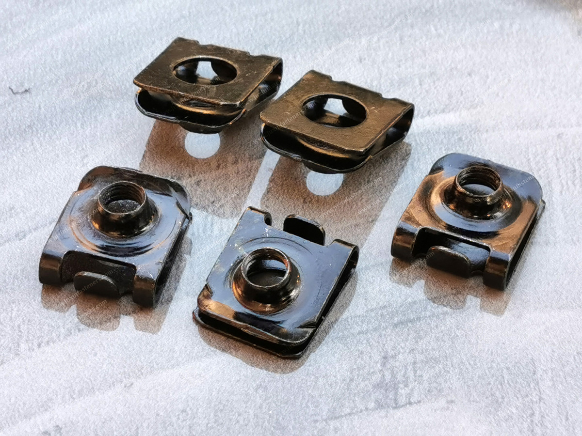
Corrosion protection is important for automotive, HVAC, electrical, and outdoor industrial applications.
Electroplated zinc is a common corrosion-protection option for suitable steel fasteners.
The required coating system should be specified according to the application.
ISO 4042 is relevant to electroplated coating systems for fasteners where applicable.
Zinc-flake coatings are a different category of protective treatment.
ISO 10683 is relevant to non-electrolytically applied zinc-flake coating systems for fasteners where applicable.
Mechanical plating is a separate process and should not be described as identical to electroplating or zinc-flake coating.
The coating must be compatible with the component geometry and intended spring function.
Excessive coating buildup may affect installation, friction, or screw engagement.
For susceptible high-strength steel components, certain manufacturing and coating processes may introduce hydrogen embrittlement concerns.
Material strength, processing route, and relevant specifications should be reviewed.
A coating should not be selected solely from corrosion appearance.
ASTM B117 may be used when a salt spray test method is specified.
However, a salt spray result does not directly predict actual field service life.
Acceptance criteria, coating system, and test conditions must be defined.
Where dissimilar metals are in contact, galvanic corrosion may require consideration in the presence of moisture or another electrolyte.
Automotive assemblies often contain numerous panel fastening points.
Clip-on nuts may be used in suitable applications where the panel geometry and joint requirements support their use.
Potential applications include:
Interior mounting brackets.
Trim support structures.
Access covers.
Dashboard support components.
Interior equipment panels.
Selected clip-on fastening arrangements may be considered for:
Exterior trim brackets.
Body panel attachments.
Wheel-arch related components.
Underbody covers.
Service panels.
Depending on the location, engineering evaluation may include:
Vibration.
Corrosion.
Temperature cycling.
Water exposure.
Coating durability.
Assembly accessibility.
Service removal.
Retention during handling.
Clip-on nuts should not be assumed suitable for safety-critical structural joints without the necessary engineering qualification.
The complete fastening system must meet the applicable vehicle and customer requirements.
HVAC equipment frequently uses sheet metal panels, removable covers, and service-access components.
Clip-on nuts may simplify selected fastening operations where the panel edge is accessible.
Equipment access panels.
Ventilation housings.
Sheet metal covers.
Control compartment panels.
Internal mounting brackets.
Engineers should consider:
Panel thickness.
Repeated service removal.
Corrosion exposure.
Vibration.
Screw accessibility.
Installation ergonomics.
Where panels are removed frequently, the durability of the clip, screw engagement, and panel edge should be evaluated over the expected service conditions.
Electrical enclosures often require removable panels and internal mounting structures.
Clip-on nuts may be suitable for certain noncritical mechanical fastening locations.
Cabinet access panels.
Equipment covers.
Internal brackets.
Control housings.
Sheet metal mounting features.
A metal clip-on nut should not automatically be considered a verified protective grounding or bonding component.
Paint, coatings, oxidation, and contact conditions can influence electrical continuity.
Where electrical bonding is required, the complete assembly must be designed and validated accordingly.
The fastening arrangement must also be compatible with the enclosure's environmental requirements.
A clip-on nut does not independently establish a waterproof or dustproof seal.
Industrial machinery may require removable sheet metal guards, service panels, and equipment covers.
Clip-on nuts may provide convenient fastening points in suitable designs.
Simplified access.
Reduced loose hardware.
Repeatable panel positioning.
Easier assembly and maintenance.
The fastening arrangement must be evaluated for:
Vibration.
Repeated removal.
Impact loading.
Panel stiffness.
Screw preload.
Clip retention.
A clip-on nut should not be selected as a substitute for a structural fastener without appropriate engineering assessment.
For production managers, clip-on nut selection affects installation time, operator workload, and assembly consistency.
Manual installation may be suitable for many applications.
Important considerations include:
Installation direction.
Required insertion force.
Operator access.
Hand clearance.
Sharp edges.
Repetitive motion.
Certain clip designs may be compatible with automated feeding and installation systems.
However, automatic installation capability depends on the actual component geometry and equipment.
Asymmetrical clip designs may require controlled orientation.
Incorrect orientation can cause misalignment or assembly failure.
The clip should remain in the intended position during the specified handling and transfer operations.
Clip installation may occur before final panel assembly.
The sequence should account for:
Coating processes.
Panel forming.
Assembly access.
Inspection.
Transportation between stations.
Final screw installation.
The cost of a clip-on nut application includes more than the unit price.
Relevant costs may include:
Clip installation labor.
Panel hole preparation.
Feeding equipment.
Assembly time.
Inspection.
Rework.
Damaged coatings.
Scrap.
Maintenance operations.
A more expensive component may sometimes reduce total assembly cost if it improves process reliability.
The result must be evaluated for the actual production system.
Possible causes:
Panel thickness below the specified range.
Incorrect clip geometry.
Insufficient retention.
Installation on an incompatible edge.
Permanent spring deformation.
Recommended review:
Verify panel thickness, clip dimensions, and retention requirements.
Possible causes:
Excessive panel thickness.
Incorrect spring geometry.
Coating buildup.
Edge burrs.
Incompatible installation direction.
Recommended review:
Inspect representative finished panels and measure insertion force.
Possible causes:
Excessive spring interference.
Sharp contact features.
Incorrect installation method.
Surface finish incompatibility.
Recommended review:
Evaluate the contact geometry, coating, and installation process.
Possible causes:
Incorrect throat depth.
Wrong hole-to-edge distance.
Clip movement.
Panel dimensional variation.
Incorrect clip orientation.
Recommended review:
Compare the clip drawing with the panel hole layout.
Possible causes:
Insufficient retention.
Incorrect panel thickness.
Excessive tightening torque.
Incompatible thread engagement.
Panel deformation.
Recommended review:
Evaluate the complete screw joint and clip retention.
Possible causes:
Incorrect mating screw.
Thread mismatch.
Cross-threading.
Excessive tightening torque.
Inadequate engagement.
Recommended review:
Confirm the thread system and assembly procedure.
Possible causes:
Inadequate coating.
Coating damage during installation.
Unsuitable material combination.
Environmental exposure.
Crevice corrosion.
Recommended review:
Assess the coating specification and actual service environment.
Different fastening methods may be suitable for different sheet metal assemblies.
| Fastening Method | Installation Principle | Main Engineering Consideration |
|---|---|---|
| Clip-on nut | Spring clip engages panel edge | Edge access, panel thickness and retention |
| Weld nut | Nut attached by welding | Weldability, process control and surface condition |
| Blind rivet nut | Mechanically deformed into a prepared hole | Grip range, hole geometry and setting force |
| Self-clinching nut | Pressed into compatible sheet metal | Sheet hardness, thickness and hole geometry |
| Loose nut | Separate threaded component | Backside access and assembly handling |
Clip-on nuts may be appropriate when:
The panel edge is accessible.
A removable fastening arrangement is required.
Welding is undesirable.
The assembly should avoid handling loose nuts.
The panel thickness and geometry are compatible.
Weld nuts may be suitable for compatible welded structures where permanent attachment and the specified joint performance are required.
Blind rivet nuts may be suitable where the fastening point is located away from the panel edge and access is available from only one side.
Self-clinching nuts may be suitable where the host sheet material and installation process support a permanent pressed-in threaded feature.
The correct fastening method depends on the complete component design, production sequence, joint loading, and service requirements.
Clip-on nuts may use different screw-engagement systems.
The correct thread designation must be confirmed from the drawing or approved product specification.
Where conventional metric machine threads are used, relevant standards may include ISO 68-1, ISO 261, and applicable ISO 965 requirements.
For conventional Unified machine threads, ASME B1.1 is relevant to UNC and UNF thread geometry.
Certain clip nuts are designed for tapping screws rather than conventional machine screws.
These applications require the correct screw and engagement specifications.
M4 nominal diameter is approximately 0.1575 inches.
M5 nominal diameter is approximately 0.1969 inches.
M6 nominal diameter is approximately 0.2362 inches.
These conversions are dimensional references only.
Metric threads are not directly interchangeable with UNC, UNF, BSW, or BSF threads.
A replacement clip nut should not be approved solely because its nominal screw diameter appears similar.
The thread system, engagement geometry, clip dimensions, and panel compatibility must also match.
OEM clip-on nut inspection should cover both the individual component and its performance on the intended panel.
Relevant characteristics may include:
Overall length.
Overall width.
Clip opening.
Strip thickness.
Throat depth.
Thread position.
Screw-engagement geometry.
Spring-arm shape.
Material requirements may include:
Steel grade.
Hardness.
Material condition.
Surface treatment.
Where specified, testing may include:
Insertion force.
Removal or retention force.
Thread engagement.
Tightening performance.
Resistance to permanent deformation.
Corrosion performance.
Functional tests should use panel samples representative of the actual application.
Testing on an uncoated steel coupon may not establish performance on a painted aluminum panel.
For recurring OEM orders, important considerations include:
Dimensional consistency.
Material consistency.
Coating consistency.
Packaging protection.
Traceability requirements.
Inspection documentation.
Customer requirements may include dimensional inspection reports, material documentation, coating specifications, and other agreed quality records.
Availability of specific reports and certifications must be confirmed during supplier qualification.
For industrial procurement teams, the purchasing specification should include enough information to avoid incorrect substitutions.
Specify the required clip configuration.
If an existing reference part is available, provide its drawing or sample.
Define:
Panel material.
Minimum and maximum actual thickness.
Coating type.
Edge geometry.
Hole diameter.
Hole-to-edge distance.
Specify:
Screw type.
Nominal diameter.
Thread pitch.
Thread system.
Screw length.
Required tightening conditions.
Identify:
Required insertion force, where specified.
Retention force.
Joint loading.
Vibration exposure.
Repeated assembly requirements.
Define the required coating system and corrosion test requirements where applicable.
Include:
Prototype quantity.
Initial order quantity.
Estimated annual volume.
Packaging requirements.
Target lead time.
Delivery destination.
A proposed alternative should be evaluated for:
Panel thickness compatibility.
Clip geometry.
Hole alignment.
Mating screw compatibility.
Material.
Coating.
Functional retention.
Installation ergonomics.
Dimensional similarity alone is not sufficient evidence of interchangeability.
Before selecting a clip-on nut or U-nut, verify the following.
Panel Edge Access
Can the clip be installed at the required location?
Panel Thickness
Does the selected clip accommodate the complete permitted thickness range?
Edge Geometry
Is the panel edge compatible with the clip opening and spring-arm geometry?
Hole Alignment
Does the clip throat depth match the hole-to-edge distance?
Mating Screw
Does the clip provide the correct screw-engagement system?
Installation Force
Can the component be installed consistently without damaging the panel?
Retention
Will the clip remain in position during the intended handling and assembly operations?
Joint Loading
Does the complete screw joint meet the required mechanical conditions?
Corrosion Protection
Is the material and coating system suitable for the service environment?
Production Requirements
Can the selected component be installed and inspected consistently at the required volume?
Commercial Requirements
Are the drawing, material, finish, quantity, packaging, and delivery requirements clearly defined?
A U-nut is a clip-style fastening component that generally fits over a panel edge and provides a screw-engagement feature.
Not necessarily. Speed nut is a broad commercial term covering certain spring-type fastening devices. The actual screw-engagement design must be verified.
The term is often used for a clip nut with a raised or extruded screw-engagement feature. Exact designs vary.
They may be suitable for certain painted panels, but the coating thickness, insertion force, surface marking, and retention must be evaluated.
The allowable thickness range depends on the selected clip design.
Not automatically. Clip retention and screw joint locking are different functions.
Yes. Conventional clip-on nuts are mechanically installed on suitable panel edges.
They may be suitable for compatible automotive trim and panel fastening applications.
Certain designs may be suitable, but the panel material and clip geometry must be compatible.
Potential causes include incorrect panel thickness, insufficient spring retention, incompatible geometry, or permanent deformation.
A U-nut generally clips onto a panel edge. A blind rivet nut is installed into a prepared hole by a setting operation.
No. Different thread systems and screw-engagement designs are not automatically interchangeable.
Provide the clip drawing, panel geometry, thickness range, mating screw specification, material, coating, quantity, and delivery requirements.
JUXIN FASTENERS supports international B2B sourcing inquiries for clip-on nuts, U-nuts, spring steel panel fasteners, and drawing-based industrial fastening components.
For automotive panels, HVAC enclosures, electrical cabinets, machinery covers, and sheet metal assemblies, correct clip selection helps support reliable installation and repeatable manufacturing.
For a technical review or commercial RFQ, please provide:
2D engineering drawing or 3D CAD model.
Existing reference part number or physical sample, where available.
Required clip configuration.
Mating screw type, size, and pitch.
Metric, UNC, UNF, or other specified thread system.
Panel material grade.
Minimum and maximum panel thickness.
Panel edge geometry.
Hole diameter and hole-to-edge distance.
Clip throat depth requirements.
Material and hardness requirements.
Surface coating specifications.
Operating temperature and environmental exposure.
Insertion and retention force requirements, where applicable.
Mechanical loading and vibration requirements.
Inspection and quality documentation requirements.
Prototype or sample quantity.
Initial production order quantity.
Estimated annual purchasing volume.
Packaging requirements.
Target delivery schedule and destination.
For nonstandard clip geometry or custom spring steel fastening requirements, please provide the relevant drawings for technical feasibility review.
Our team can review the submitted specifications and confirm applicable product sourcing, manufacturing feasibility, and quotation arrangements.
Company: JUXIN FASTENERS
Website: www.juxinfasteners.com
Email: info@juxinfasteners.com
Contact JUXIN FASTENERS with your engineering drawings, panel specifications, and purchasing requirements to request a quotation for clip-on nuts,
U-nuts, and related OEM sheet metal fastening components.
Product Packaging
Packaging Standard
At Juxin Fasteners, we apply standardized export packaging to ensure product protection, traceability, and compliance with international logistics requirements.
1. Standard Export Packaging
Unless otherwise specified, all products will be packed according to our factory standard export packaging, which includes:
Moisture-resistant inner protection
Poly bag or small box packing as required
Reinforced export cartons
Clear labeling with part number, specification, batch number, and quantity
Palletizing for sea or air shipment when necessary
Our standard packaging is designed to ensure safe transportation, efficient warehousing, and long-distance international shipping.
2. Customized Packaging Options
We also provide customized packaging solutions according to customer requirements, including but not limited to:
Private labeling
Customized barcodes
Specific carton dimensions
Retail packaging
Special pallet configuration
Customer-specific marking and identification
So that you know, customized packaging may involve additional costs and extended lead time depending on the complexity of the requirements.
3. Compliance & Quality Assurance
All packaging processes are controlled under our ISO 9001 quality management system to ensure consistency, traceability, and product integrity throughout the supply chain.
Product Pictures
Hot Products
Contact Us
Tel.:
+86 020 8621 0320
+86 020 3121 6067
E-mail:
Technical Support:
Navigation
SEND INQUIREY